for the Flite Test Simple Cub Note: 07/23/18 The notes were started after version 1 was completed and apply to versions 2, 3 & 4. April 10, 2018 Added 1/4" by the thickness of the foam board strips to the bottom, rear of the fuselage sides from the Doubler to almost end of fuselage to keep bottom from pushing in. May 5: I think I used 9x5" prop on the V2 version. Note: 07/23/18 I have no idea why I wrote about the prop here and why the font was red. Pin-pricked the foam board all the way around the Doubler outline on the plans/template for the fuselage sides for better placement and alignment of the doubler. On the top hatch, the paper gets folded under to create the angle, not where the paper was removed. I used 3/32" wire for landing gear. The wing chord is 8". I calculated 2" for CG, they recommend 1.75" and that's what is showing on the wing. That's safe. May 5: There is more to CG than just calculating it. The H-Stab incidence is more critical than I thought. I calculated the wing area with extra piece of Ross foam board I had on hand, using the weight technique.
Plan form wingspan = 38.34" or 973.8mm, FT notes it as 38.00" or 956mm 3/16" dowel used for wing hold downs. I should NOT have popped out the slots that say Remove after Assembly. Wing panels should be joined to keep from any leading and trailing edge problems. April 11, 2018 Had to redo holes in power pod for ESC, reference finished Cub. Some Weights:
Fuselage RTF w/GenAce 3S 1000mAh LiPo 389.4g or 13.74 oz. Fuselage NO battery 293.1g or 10.34 oz. Plane Ready to fly weight 499.7g or 17.63 oz. but it is nose heavy at this time Note 07/23/18 I'm not sure what definition of 'nose heavy' I was using. On today's date the Flite Test Store Web page for this plane states "Weight: 10 Oz (Fully assembled; without battery)". Remember the strips along the bottom of the fuselage sides toward the rear. April 11 EFO meeting Note 07/23/18 regarding version 1 as shown at the meeting
April 12 Fixed Dihedral problem using 2x2 lumber instead of dihedral gauges.  Added 3/16" x 2-3/8" plywood servo rails through the version 1 fuselage and marked the fuselage sides. Also had to redo the pushrod lengths and make them shorter. This method for mounting the servos and running long pushrods was not used on the final version.  April 13 New Weights Wing 112.0g was 110.3g Fuselage NO battery 297.6g was 293.1g Fuselage with Battery 394.0g was 389.4g 6 #64 rubber bands 5.7g New Plane Ready to fly weight 511.7g or 18.05 oz. but still haven't added tail skid or cut off some of the hold down dowels. Changes to this point reflected in Area and WCL Area wing loading: 8.87 oz./sq.ft.
Added skid using 1/8" music wire, two small pieces of 1/16" plywood and a two small pieces of 1/8" plywood. Glued with 5-minute epoxy (I need new 5-minute Epoxy) Wing the same 112g Fuselage NO battery 309.0g was 297.6g difference 11.4g Plane with NO battery 421g Fuselage with Battery 405.4g was 394.0g difference 11.4g Tail weight/tail skid added 11.4g = 0.4 oz. Final Ready to fly weight 523.1g or 18.45 oz. Area wing loading 9.07 oz./sq.ft. WCL 6.36 CG checked and still seems slightly nose heavy, but I'll fly it this way. Throws checked by measuring:
Balanced 2 each APC 9x6E and APC 10x7E. Measured missing area from wing rectangular plan form, which I still had, and found about 7 sq.in. missing from the rectangular shape on each wing panel. I also watched several parts of the build video, especially installing the servos with hot melt glue. I don't believe it is/was a good idea! I charged the Emeter II and made up some leads for the RPM checker on the RDU for the meter. April 14 Emax MT-2213-935Kv weight 53g The motor recommended by FliteTest
After reading some comments yesterday on the Flite Test Forum I realized that I could have/should have moved the servos to the rear as a solution for the nose heaviness. I cannot find any reference to the model being nose heavy no matter where I look on the Internet, YouTube or Flite Test Simple Cub threads. That's driving me nuts! May 5: I am really worried now that the plane was not nose heavy in the practical sense and I may have to reposition the servos. Only the glide tests and more flight tests will show if I need to do that. Another conclusion that I jumped to that I should not have. It just proves that there is a lot that I think I know that I don't really know. My fuselage came out with the horizontal stabilizer being slightly 'crooked' across the fuselage when measured from the same point on each side of H-Stab. I read online this morning, didn't save the URL, that the fuselage sides are not identical on the plans. I put the fuselage plans in TurboCad and eliminated the fold-over center and mirrored the left side. I changed the color on the left side and slid it over the right. I found that the sides are absolutely identical, so any problem was caused by my cutting and not the plan. I spent/wasted Thursday creating a drawing to add servo rails and adjust the pushrod lengths and then added the tail skid on Friday because of the plane being nose heavy. I just should have moved the servos back. HEAD SLAP!!! I still need to move the servos to the back on my Fuselage plan. Right now I'm concerned that my original prototype V1's nose heaviness was a fluke. As I stated, the nose heaviness is absolutely not reported anywhere else and my motor choice and prop weights are not much different from the recommended MT-2213. This is just weird and driving me nuts. Note: 07/23/18 It turned out that my motor's total weight with cross mount and prop adapter was significantly heavier than the recommended one. I don't understand why FT always recommends SF props. All videos of this plane flying show speeds well above what SF props are typically used with. The weather is crappy. Rain all this weekend. I really want to fly this plane. I don't know whether to redo the drawing to include servos in the tail or not, as this prototype could just be a fluke. I've been up since 3:45 a.m. I brought the GensAce and Dinogy batteries upstairs to warm them up and charge them. Also brought up the charger and 12V Marine/RV battery. I looked again at the rectangle area missing from the Ross foam board cuts used to calculate the wing area. Started charging the GensAce battery on charge at 7:15 a.m. at 1 amp. Started charging the Dinogy at 8:30 a.m. at 1 amp. Did Power Check for 10x7E and 9x6E. GensAce on 10x7E and Dinogy on 9x6E. 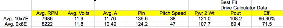
Batteries returned to storage voltage. Calculated Stall Speed 11 mph
April 19, working on second fuselage Cut outline of parts that have hangover edges before the 50% lines to remove the foam Remember to glue the cut faces of the moveable surfaces once sanded. April 20 4:40 p.m. Finished 2nd fuselage version New Specifications for Version 2 with servos moved to the tail and 3-1/4" dowel tail skid on rudder Wing 112g Fuselage NO battery 298.6g or 10.53 oz. Plane with NO battery 410.6g 14.48 oz. Fuselage with Battery 395g or 13.93 oz. Final Ready to fly weight 507g or 17.88 oz. Using wing area of 293 sq.in.
CG checked and it is absolutely dead on with the recommended CG of 1.75" with the battery back as far as it can go. Throws checked with 12-deg gauge. Rudder was perfect. Up on the elevator was less. I think it is because the servo arm will not sit straight on the HS-53s. :-( Note: 07/23/18 I had not adjust the sub-trim on the servos. Tail Skid on Rudder found at https://youtu.be/Uw0_9Zmcewc?t=4532 In the video Josh said, "This step is optional, but it works great." He never said how long the skid is. May 5: After the flight test, I found the skid to be useless for take off and landing. The tail rises almost immediately when power is applied. I'm not sure it is necessary or a good idea. April 25 I realized that I didn't draw the hatch correctly and it had raw edges.
The Fuselage bottom parts, front and rear, ONLY need to be changed if the landing gear is finally moved forward and then the front bottom will also have to be modified. April 26
Winds out of the west. 5 mph - 10 mph at the park on 5 Mi. Rd.
I am an idiot. I put down trim on the plane instead of right trim. :-(
What I did
Thought about making new Power Pod with right thrust but passed and used washers to achieve right thrust to keep with FT design. Made 1/2" by 1-3/16" high doublers for the inside, front of the Power Pod and laminated to the inside of the front of the Power Pod to give the firewall more gluing surface. Removed paper on laminated doubler sides. Cleaned up the inside of the original 3/32" plywood firewall with a sanding drum in the Dremel. Epoxied the firewall back onto the Power Pod with 1/16" of the firewall bottom below the bottom of the Power Pod. While epoxying the firewall back onto the Power Pod, I noticed that plywood was pushed in in the middle. That confirms my suspicion that the firewall is too thin. Used strapping tape, not packing tape to reinforce the firewall onto the Power Pod. I marked the wing for the CG to be 2" behind the leading edge of the wing. I made two trailing edge wing protectors out of 1/16" plywood, 3/8" wide and 2-1/2" long. I sawed about half way through at about 15/16" with the short end fitting on the center section and long end on the wing. Sawing allowed the wood to break so that it could be set to the angle between the center section and the wing dihedral. I glued them to the center section using Titebond. I reattached the motor to the firewall with washers under the two screws on the left fuselage side. I slid the Power Pod in and secured it with the 1/8" dowels. I placed weights on the tail until I achieved the CG at 2" inches. I glued the weights, 0.5 ounces, in place on the fuselage bottom just in front of the rudder. I centered the trims on the transmitter and very carefully reset the rudder and elevator to neutral. I still have to reweigh the wing and fuselage, as weight will have been added since my last weighing. April 27 These are weights of version 2 after repair to firewall/Power Pod after flying on April 26 New Specifications for Version 2 with servos moved to the tail, 3-1/4" tail skid on rudder and 1/2 ounce weight near tail. Also added plywood wing protectors to TE of wing. Wing 113.4 or 4 oz. up from 112g or 3.95 oz. Fuselage NO battery 319.8 or 11.28 oz. up from 298.6g or 10.53 oz. Plane with NO battery 433.2g 15.28 oz. Fuselage with Battery 416.1g or 13.93 oz. Final Ready to fly weight 529.5g or 18.67 oz. Using wing area of 293 sq.in.
CG moved to 2" behind leading edge of the wing by adding 1/2 ounce of tail weight. BUT Being an idiot, I should have just used heavier servos. I replaced the HS-53 rudder and elevator servos with HS-82 servos. I removed the 1/2 oz. of lead in the tail and replaced its 'hole' with a foam board patch. That worked out perfectly and the CG is at 2" with the GensAce battery installed. I made changes to my Fuselage Templates for the Hitec HS-82 servo holes. I used the sub-trim on the transmitter to center the servos. and be sure the same pushrods can be used. While installing the new servos, I noticed that the landing gear was wobbly in the FT slot. On inspection I found that the wire gear had enlarged its slot in the Landing Gear Tab. I forced epoxy down the gear legs in the Landing Gear Tab using a toothpick. I also noticed that the gear coming back after the 3 not so great landings was enlarging the gear slots in the fuselage sides. I didn't do anything to fix that, as I am still expecting that the gear has to be moved forward. I also have to reweigh the fuselage with the new changes. Calculated the CG using online calculator
Static Margin:
Static Margin should be between 5% and 15% for a good stability. Low Static Margin gives less static stability but greater elevator authority, whereas a higher Static Margin results in greater static stability but reduces elevator authority. Too much Static Margin makes the aircraft nose-heavy, which may result in elevator stall at take-off and/or landing. Whereas a low Static Margin makes the aircraft tail-heavy and susceptible to stall at low speed, e. g. during the landing approach. * Choose Low Stabilizer Efficiency if the stab is close to the wing's wake or behind a fat fuselage in disturbed flow. Choose T-tail for most gliders. Simple Cub 5% (low static margin) CG 2.5" from LE
Later April 27
New Specifications for Version 2 with HS-82s in the tail and 3-1/4” tail skid on rudder. Also includes plywood wing protectors to TE of wing. Wing 113.4 or 4 oz. up from 112g or 3.95 oz. Fuselage w/6 #64 rubber bands but NO battery 326.7 or 11.52 oz. up from 298.6g or 10.53 oz. Plane w/6 #64 rubber bands but with NO battery 440.1g 15.52 oz. Fuselage w/6 #64 rubber bands and with GensAce 3S 1000mAh Battery 423.2g or 14.93 oz. Final Ready to fly weight 536.6g or 18.93 oz. Using wing area of 293 sq.in.
CG moved to 2" behind leading edge of the wing by going to larger Hitec HS-82 servos. April 28 I called Mike about dihedral, 1/8" firewall, servo order, hope not building yet Built new 4-ch wing April 29 Added and epoxied standard dihedral to the new aileron version of the wing using the dihedral guides and 1x2 wood
These weights are after changing to 4-Ch aileron version wing. New Specifications for Version 2A (ailerons) with HS-82s in the tail and 3-1/4" tail skid on rudder. Also includes 1/32" plywood wing protectors on TE of wing, 2 Hitec HS-53 servos, std. wire pushrod and large GP control horns for ailerons in wing, Cobra 22A changed to Cobra 33A ESC, "Y" harness and 3" servo extension in fuselage. 4-ch Wing 145.4 g or 5.13 oz. up from 3-ch 113.4 or 4 oz. May 5: Added over an ounce to the wing Fuselage w/6 #64 rubber bands but NO battery 341.9g or 12.07xx oz. up from 326.7g or 11.52 oz. Plane w/6 #64 rubber bands but with NO battery - didn't do it Fuselage w/6 #64 rubber bands and with GensAce 3S 1000mAh Battery 438.3g or 15.46 up from 423.2g or 14.93 oz. for 3-Channel Final Ready to fly weight 583.7g or 20.59 oz. up from 536.6g or 18.93 oz. for the 3-channel Using wing area of 293 sq.in.
CG kept at 2" behind leading edge of the wing with these changes. Battery Placement stays the same. When the wing was attached to the fuselage, both ailerons moved up in relationship to the area on the wing near the center section. I readjusted them to the area on the wing near the center section and now they look down when they are off the plane.
Made and glued on 3 rear center section reinforcement strips to keep wing center section from compressing when rubber bands are applied. April 30 Broke the landing gear loose in the Landing Gear Tab when trying to put the wing on while the plane was setting on the gear on the workbench. Fixed with hot glue (wife's gun). Put wing on plane and re-centered servos. Seems to me that if ailerons are adjusted for flight, the wing MUST be kept on the fuselage after that, otherwise the trim will be off when the wing is put back on the plane, but maybe not if it's never adjusted off the plane. Went flying at Midwest. From about 9:45 to 11. Winds were stronger than predicted. Using Revo pack; 3 test hops into the wind. Plane still nosed into the ground on the test hops. Decent angle is too steep. Revo was set in 'normal' place for 3-channel. Felt tail heavy in the air. After landing I found that CG was not at 2" from LE of wing. Gear bad after landing. Velcro wouldn't stick to close hatch. Side of fuselage breaking out. Timer didn't start. Gear was in original position, not optional forward position. 2nd flight on Revo pack: Moved the Revo pack all the way forward to achieve 2" CG. I found the glide slope too steep in both the air and when landing. Timer didn't start again. Turned LG Tab around. Gear held on landing but nosed over. Battery plate loose again. 3rd Flight Dinogy 70C pack. Aligned front of pack with the dowel going across the fuselage. Timer fixed - 6 minute flight Still too tail heavy (I think) and nosed in on landing. The LG was totally buggered. Wrapped LG Tab with painters' tape. It was what I had. Put landing gear in forward slot. 4th flight: Installed GensAce 'backwards' so that it could be as far forward as possible. Wind and Gusts came up during this flight. It actually flipped the plane over backwards over itself twice. I felt that the plane really needs aileron and rudder mixing. I fought the landing after 3 minutes and 9 seconds of flight time. I had the gear in the optional forward slot for this flight. I nosed it in on landing, so couldn't tell about gear positioning. Strapping tape the LG Tab is a good idea. Plane is extremely pitchy and sensitive to CG changes. It definitely needs more down thrust. The right thrust provided by the washers seemed okay. I think the trailing edge is acting like flaps. Can I close the ailerons? Tail skid is useless as tail doesn't stay on ground. Goes up on the mains quickly. Seems to like a little power on landing to pull up the nose. Firewall appeared to be staying in at the flying field. On way home picked up #33 rubber bands at Staples. At Home Discharged Turnigy Nano Tech - it was't used.
Charged Dinogy 70C to see how many mAh were returned to the pack after 6 minutes.
340mAh returned which is .34Ah times 60 minutes in an hour = 20.4 amp minutes / 6 minutes = Avg. Amp draw of 3.4A. Discharged using commercial discharger to 3.77V per cell. Discharged Revo after taking voltages, 3.896V, 3.894V, 3.900V. This was after 3 hops and two flights.
Charged GensAce.
Visual Inspection of Plane at Home Before Removing Rubber Bands #64 rubber bands are really pressing into wing. 1/32" plywood rubber band protector loose at center. The protectors were put on with hot melt glue before going to the field this morning.
I stopped at Staples on the way home and got some #33 rubber bands to try next time. These are the best size to use on this plane.
While waiting for the glue gun to heat up the glue, I checked RC Groups and then the FT forum.
It is too late in the day, almost 4, so I'm not going to make anymore repairs or changes until I sleep on it. Right now, I see the problem being that the plane won't glide. I don't know what to do about that. I'm going to watch the Simple Cub flying videos again and check out other FT plans like the Bushwacker and other one I can't remember for and check for decalage. I'm thinking the plane might need some wing incidence. While looking at video found motor mount problem in the FT Float video. Another nose over in the Tubby Cubby video. May 1
Recalculated and drew new wing.
May 2 Started test gliding the plane here Totally frustrated with the Cub not gliding.
Called Keith.
I removed the H-Stab and Rudder and reset the H-Stab incidence to about 2 degrees. I glued in the H-Stab at the new +2 degree angle of incidence. IT IS IMPORTANT TO NOTE THAT ALL OF MY SPECULATION ON THIS DATE PROVED FALSE! May 3 Double checked the new H-Stab angle. It was very close to what I calculated as +2 degrees.
Cut cutout for Velcro a little deeper in fuselage side and spread a thin coat of Titebond on the slot so the Velcro could have a better surface to 'grip' on. Front, left dowel had pulled back after the several nose landings from the glide tests I performed yesterday. I filled the 'hole' behind the dowel with a toothpick and glue. I reattached the Rudder using strapping tape. Reaffixed the GP control horn to the Rudder and slipped the rudder control clevis back into the horn. Needs to be centered again. Replaced rear 1/8" dowel Power Pod hold in. It was broken. Reinstalled Elevator pushrod and slipped clevis into GP control horn. Needs to be centered again. Put new piece of Velcro in slot on fuselage front for the hatch. Glued and pinned the DTFB crosspiece between the two Landing Gear Tab Slots. It broke out during flight testing at the flying field. Made new foam board LG Tab. Removed wheels and wheel collars from LG and removed LG wire.
Placed LG and Tab under a brick. Wrapped LG Tab with strapping tape on May 4, not today. Measured angle of motor with 1 washer using TurboCAD. It measured 1-1/8" (motor mount width) by 0.0345" for thickness of the washer. Surprisingly, that was 1.8 degrees. New Power Pod, I'll use 1.5 degrees of right thrust to allow for washer sinking into wood some when tightened down. Drawing and printing of new Power Pod completed with 1.5 deg right thrust and 2 deg down thrust, I think. New 1/8" plywood firewall made. New Power Pod cut out. Placed Firewall against it. Looks okay. Glued Sides to Power Pod floor. Sides are just shy 1-1/4" high. That measurement is for the 1/2" wide firewall doublers. Also reviewed the whole FT Swappable forum looking for the word cub and found a lot more info. Check the FT Cub stuff from Internet pages document. May 4 Worked another two hours in CAD trying to figure out what is going on at the front of the airfoil and I can't get the measurements to work. Very frustrating. Epoxied the 1/8" plywood firewall onto the new power pod. Yesterday, I put a comment on the FT Swappable forum about test gliding the Cub. There were two comments when I got up. One was added after the first two, but it wasn't on topic, which is typical. Strapping taped the landing gear Tab and trial fitted. Both slots okay. Put wheel collars and wheels back on landing gear. Strapping taped the new 1/8" plywood firewall onto the new Power Pod. Discovered that the holes for the Power Pod dowels had pulled forward. This surprised me, as the plane was always landing on its nose in the glide tests. That should have pushed the dowels rearward not forward. Put strapping tape over the holes going in both directions. May 5 Too many changes. Because we've had no flying weather, I think I may have made too many changes at once. The new tail incidence has not been tried yet, so I don't know if the new Power Pod down and right thrust angles will be correct. The V2 version fuselage is pretty beat up and I've not really learned enough, except that the FT design wants to land on its nose when gliding. I am comfortable that the landing on the nose is not caused by a stall of the high lift section of the wing towards the tips, as the Cub wing produced the same glide angle on the Stik. I noticed yesterday that I have an ounce and a half of lead in the nose of the Stik and that the CG is way forward. The FT Cub's nose is not as long as the Stik's. Now I am wondering, will I need more nose weight? Where's the CG going to be to be correct. I have just too many questions remaining and I am frustrated that the weather has been stopping me from finding the answers. I'm going to read through this whole document now to remind me what I think I've learned and add any annotations, in red, that I think might be useful. It is about 6:30 a.m. There is no wind. The grass is covered with heavy dew. The question I have is should I sacrifice the fuselage to the wetness to check the glide now or not, and which wing should I use for the glide test. This plane has become an obsession that I just can't get past, and it is bugging me, as I have other things I'd like to get to! 7:15 a.m.
2 Glide tests, angle is better but still landed on nose. Brought in and dried off. Removed the 1.5 ounces of weight on the front of the Revo pack but left pack in the most forward position. That moved the CG to approximately 2.5". One toss, glide slope seemed better. Turned pack around to where I planned the pack to go. One toss, best glide slope yet. I dried off the plane but haven't changed anything. Thoughts before checking CG
It may need 1.5 degrees, not 2 degrees on the stab or possibly tail weight. I'd like to have done more than one toss each, but the plane was getting pretty beat up and the dew was still heavy. I did wipe off the plane after the 2nd toss with the Revo in the designed position. Measured CG. It is between 2-3/4" and 3". It is not quite hanging nose down at 2-3/4" and is noticeably hanging down at 3". Looks like it is worth putting in the new Power Pod and flying it with the new right and down thrust. At this point, I am feeling better about the plane, but, unfortunately, I've felt that way before. :-( Remember to add rudder mix to the aileron. Receiver came off of Velcro again during tests today and the previous glide tests as well. Keep an eye on it. Removed Power Pod. Pre-screwed holes in new Pod's 1/8" firewall using spar mount to get angles correct on the screws. Pulled strap off old power pod. Measured and cut holes for the ESC wires and zip tie used to hold extra length of motor wires. Oh RATS! While cutting the holes in the bottom of the power pod, I discovered I'd used 3/32" plywood again for the firewall. :-( It must have gotten in with my bundle of 1/8". I measured it using my Midwest rule and it was bigger than 3/32" so I assumed it was 1/8". It wasn't and I made another firewall for Mike out of this same plywood. Crap. Glued the battery strap from the old pod onto the new one. Remember to add cutout from the fuselage top to the wing plans for alignment.
Put Velcro on the bottom of the Power Pod for the ESC and saved the other piece for the inside floor of the Pod for the battery. Installed the Power Pod and found the sides of the fuselage were not perfectly square and the Power Pod sides were close to square. The right side of the firewall was sticking above the hatch bottom. I sanded it down at an angle and got it down a tad too much, but it will work. The size of the firewall is correct IF the fuselage sides are parallel to each other. Duh! I created the holes in the new Power Pod. I removed the Power Pod and installed the motor and ESC. I tie wrapped the motors between the ESC and motor. The Power Pod was reinstalled and the 1/8" dowels inserted to hold the Power Pod into the plane. All clevises were checked to see that their 'keepers' were in position. The prop was reinstalled on the motor. The landing gear was installed in the rear, FT position, and the dummy LG Tab inserted in the my front position. Both the rudder and elevator control horns seemed a little loose. I tightened them. Remember, do NOT put the wing on when the plane is setting on its LG. Set it on the stand to put the wing on!!! The 4-ch wing was attached while sitting on the Robart stand. The Revo battery was installed and CG checked. It balanced at about 2-1/4". It may need tail weight. It looks like the right wing panel is down a lot compared to the new H-stab position. I made a 1/16" thick by 3/16" wide by 5-3/4" long shim and pinned it place. It was too much. I then did a 1/32" thick shim and it was too little. I sanded the 1/16" thick shim a bit, checked it and glued the shim on the top right side of the fuselage. Set rudder mixed 10% to ailerons. Left wing panel servo didn't work until I swapped connectors on "Y" harness. Forgot to check if rudder is doing anything to ailerons. It shouldn't. Should be good to go, except for being sure rudder is NOT moving ailerons. Build a fuselage jig. Build a H-Stab jig, once the angle has been actually determined. On the final version, the front of the LG Tab should be 3/16" plywood. May 6
We ran into a major 'issue' with the road repair at the Midwest flying field, so I got a couple of flights while the CAT was working on the major swamp/drain area. The road is not looking good there right now! Flight 1: Short and DUMB!
Flight 2: I put in the 1/16" shim, thinking that the 2-degrees of positive incidence was too much, but then I found out I had no elevator. :-( Reseated the elevator servo lead.
Flite 3 3/32" shim
The CG at home was at about 2".
The down thrust seems good, but that will change IF I change the positive H-Stab angle to 1 degree instead of 2 degrees. May 7 Nothing I'm doing seems to be making the plane fly decently. I decided to set it up with the wing having the equivalent of 2 degrees of positive compared to the H-Stab. I made pieces to fit on the rear of the fuselage to set the angle to -2 degrees on the H-Stab. Once again the Rudder and H-Stab were removed from the plane. The angled pieces were glued onto the rear of the fuselage and aligned with the top of the fuselage. A new Power Pod was made using 1/8" plywood for sure this time and only 1/2 degree of right thrust. The paper at the hatch hinge was glued back down. It was coming loose. The wing hold down dowels were cut to 3-3/4" total length since they were too long and the rubber bands would slip into the aileron slots. Just over 1/2" is sticking out of each side of the fuselage. With the sides not parallel to each other, the H-Stab is once again glued on at a cocked angle, but it looks opposite of what it was before. Figures. Making guides for the H-Stab is a good idea. Got the new H-stab angles set and glued to the fuselage. Set the wing so it matches the spanwise angle of the H-Stab. Hooked up the servos. A new elevator pushrod was necessary. The firewall is epoxied to the Power Pod. Still needs strapping and the power system reinstalled. Plane just about ready to test fly again. Needs final check over and making sure that ALL servos are hooked up securely! May 8 If the plane needs more weight in the nose, then HS-53s in the tail would help. It just occurred to me, that for today, I can add more nose weight, if it survives the first test flight, by making a shim or two to add to the rear end of the power pod. I'll do that next, as soon as the batteries are charged. This plane is giving me total fits! I want to get it flying decently before Mike spends his time and effort in building one!!! Using DTFB I made a 1/4" shim and a 1/2" shim to go on the rear of the Power Pod and drilled the appropriate holes through the Power Pod sides so that I can change the CG by moving the Power Pod. Just checked Windfinder. I don't like the predicted winds out of the south at up to 8 mph and gusts of 16 to 17 mph. This afternoon looks better after 3 p.m. USAIRNET just notes winds of 5 to 6 mph. I forgot to order APC 10x5E and 9x4.5E when I placed my Tower Order yesterday. I am balancing the two APC 10x6E props I bought at Toledo. I changed the amount of rudder mixed to the aileron to 15%. Just thought of a problem with the DIY version, that shouldn't be a problem with the laser cut kit. The sides are not exactly the same. One will always be cut out a little bit different from the other.
To keep the fuselage square, it might be a good idea to cut several 90 degree DTFB pieces and pin them to the outsides along the fuselage. My V2 was not square and ended up causing alignment problems between the wing and H-Stab. May 10 Found a video titled "Aaron Flies the Cubby" showing the Simple Cub. I'd not thought to look under the name 'Cubby' for videos.
Yesterday, May 9 was another frustrating day trying to figure out what is going on with the wing profile (Cub-wing-profile.tc2) and it was too windy to test fly again and check out the -2 degrees on the H-Stab.
I tried to make a profile of the wing airfoil 4" wide to see what was going on and whether it was truly a flat bottom airfoil. It turned out to be more frustrating than it should have been. I finally decided to glue some of the profile together, and after returning from the Midwest rainout/wind out meeting flipped the top over the bottom of the profile and found it to be truly a flat bottom wing. Earlier in the day, I found a Web site, About Model Aircraft Airfoils, that noted that true flat bottom wings are the worst.
True flat-bottom airfoils are a poor choice for any design. They are next to impossible to trim properly because they are extremely speed sensitive. It may be possible to trim this trait out, but it means spending hours tweaking the wing incidence, decalage and engine thrust.
I've never flown a model with a flat-bottom airfoil that could even come close to being trimmed as it was built. I don't particularly enjoy cutting the tail off my planes numerous times attempting to get it right. By that he means some kind of entrance both at the top and bottom of the airfoil, like a Phillips entrance. KM
Flat bottom airfoils (He's talking modified flat bottom KM) are used for powered aircraft that are willing to make the compromise of having more drag in exchange for slow flight or high lift capabilities. They do not penetrate the air well but can stay aloft at very low speeds. I have built a handful of models having flat bottom airfoils that can hover right in front of me because the aircraft's minimum flight speed was below the wind speed. For example, if the model can fly at 10 MPH and the wind is blowing 15 MPH then the model can fly backward (relative to the ground) at 5 MPH. As far as the air is concerned (which is the only thing the airplane cares about) the aircraft is flying forward at 10 MPH. An aircraft that is identical except for having a symmetrical airfoil will have a higher minimum flight speed." Things I think I learned so far.
I should try to fly the aileron Cub wing on the Stik and see what happens. I was able to complete the wing profile in CAD using the model of the airfoil that I created. It looks like the static angle of attack is 0.5 degrees at best. For a 2 degree static angle of attack (AOA) I should have used the 3/16" shim I had for the wing. I figured that using the fuselage-profile CAD drawing. May 11
I checked the Basic Proportions for R/C Model Aircraft by Andy Lennon. It notes that the H-Stab area should be between 18% to 22% of the wing area. The wing area is 293 sq.in. and the H-stab is 55.023548. 293 / 55.023548 = 18.8%, so it falls 'in range'. From the CG of the wing to the CG of the H-Stab it should be 2.5 to 3 times the wing chord. The wing chord is close to 8". 8 * 2.5 = 20" 20" puts the H-Stab CG in the middle of the rudder somewhere and way off the end of the fuselage. The Cub is a horrible plane to model as the proportions are extremely poor, especially the tail moment. I took a look at the FT Tiny Trainer and could see that the nose moment is long enough, but tail moment is once again too short. I got out my Robart meter. Using the SuperEZ, which also has a flat bottom wing, I set the H-Stab to 0 degrees and found the wing incidence to be +2 degrees compared to the H-Stab. I did not measure the down thrust angle, if any. The H-Stab area on the SuperEZ is larger and a greater percentage of the wing area than the FT Cub. May 12
The Old School has no decalage like the FT Cub. I was hoping for a video of it flying. I checked the digital edition and no link to video. The wing area is not given in the article. Based on the given RTF wt. of 7.2 oz. and given wing loading of 6.75 oz./sq.ft. the wing area is 1.067 sq.ft. or 153.6 sq.in. The WCL is then 6.5, which is in the park flyer range. I could not find YouTube video of this plane, but I did find a Larry Kruse at the Lawton Area Fun Flyers. I downloaded Pat Trittle's Pietenpol from the Oct. 2017 MA. I did only the fuselage ratios. The nose moment was a 'tad' short and tail moment not too bad. There was 1 degree of positive incidence on the wing. That was interesting. The airfoil is not totally flat. There is a bit of an entry on the bottom of the airfoil. I did download the Pietenpol wing and H-Stab but never calculated the ratios between them. Most interesting was that Pat chose to include 1 deg of positive incidence in the wing. For my first test on the next test day (maybe tomorrow/Sunday evening), the Stik was set up with the 4-ch wing. I had to reverse the ailerons in the Tx. Be sure to double check everything.
Remember to remove LG from Cub before testing it, if I can get that far. Interesting comments about FT Power Pod found here May 13 At this point I have been so focused on having no decalage, that I've not considered other possibilities. The tail moment is short, just a tad over 2x the wing chord wing MAC to H-Stab MAC. Could the air coming over the wing be disrupting the airflow over the H-Stab. The question would then be, "Would raising or lowering the H-Stab help?"
In the "Basic Proportions for R/C Model Aircraft by Andy Lennon" it shows that the percentage of wing area to the H-Stab area can decrease with longer moments. The question is, "Should the H-Stab area be enlarged as it is 18.8% of the wing area." (See May 11 notes) I am perplexed. I have the H-Stab set at about -2 degrees for testing today if possible, but that may not be the answer. No one has answered my question about gliding the Cub where I asked it on the Flite Test Forum. I just checked the CG on the Stik with the Cub 4-ch wing on it and it is at 1-3/4" from the leading edge, as recommended for the Cub. After watching the video of my modified Old Fogey landing on YouTube this morning, it occurred to me that I might be the problem and that it is not a design problem at all. I could here me saying to Norm, "Give it just a bit of power before it lands." Maybe that is all that is necessary with the Cub. I am totally grasping at straws. I found the other Simple Cub thread on RC Groups that I was looking for; Aircraft - Electric - Airplanes Beginner Training Area (Aircraft-Electric) Help! My plane never flew May 14 Flying notes from the evening of May 13.
Flight 1: My Stik flown with the Cub 4-ch wing. Wing incidence of the Cub wing on the Stik was measured at 0 degrees with the Robart incidence meter. The H-Stab and down thrust are 0 degrees on my Stik. The plane was left together from measuring the wing's incidence angle, so as not to disturb the measured incidence. The CG with the GensAce pack was between 1-1/2" and 1-3/4" from the Cub wing's leading edge when measured in the holes on the Cub wing. To achieve this the battery was placed as far forward toward the firewall as physically possible. Stik H-Stab Area: ~70 sq.in. which is 23.89% of the Cub wing area of 293 sq.in.
The flight 1 notes:
The 4-ch Cub Flights For all of the Cub flights, the rudder was mixed into the ailerons by 15%. That proved to be just about right for good control on the turns. Flight 2 (flight 1 with the Cub) notes:
Fight 3: The Power Pod was moved forward by 1/4". I did not note the CG. No Landing gear on the plane. The control in the air was good, but changing the flight speed from cruise up just even a little bit caused a huge climb. The landing was a good belly landing. Flight 4: The Power Pod was moved forward to the 1/2" forward point. The landing gear was inserted into the forward most position and the filler in the rear LG position. The CG appeared to be about 2" at the flying field using the holes in the wing. The take off was from the ground. The plane flew pretty well, but still wanted to climb a lot when too much power was applied for simply cruising around on this almost no wind late afternoon. It landed pretty well on the wheels but nosed over and then plopped back down into a 3-point position. The grass was relatively long and very wet from recent rains. Notes from the flying field:
At home notes:
Proposed Fuselage V3 changes from V2:
Starting Design of Fuselage V3 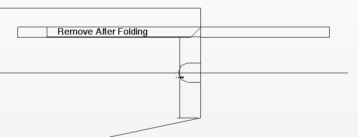 Putting the bevel on the horizontal stabilizer and not the elevator means that there is possible interference with the rear of the fuselage.  In the video it looks like the rudder hinge is very slightly ahead of the elevator hinge. I did it like this with the V2 fuselage. It must be the cutouts in the H-Stab stop the H-Stab from going too far forward on the fuselage. I accidentally did the rudder this way on the V2 version, and it was no real problem, and actually better for attaching the GP Long Control Horns. I am really, really bothered about reports on the Internet of it flying well as designed. It is really holding me up, as I know it didn't fly well. At least I didn't think that it did. mrjdstewart on the flitetest forum noted, "maiden mine today and it flew awesome. funny prop noise, but flew great. did multiple, epic, touch and goes. didn't even use the flapperons. on landing and post flight, realized i hadn't put the power pod skewers back in. pod was working it's way out the front of the plane!" May 15 I really beginning to not trust my own judgement.
I double checked the angle on the fuselage doubler and it is 2.3 degrees. Kind of finished up templates, but not quite. May 16 Finished up templates and printed. Make 1/8" plywood to cut the top and bottom lines of the H-Stab. Cut ONLY the front lines of the H-Stab slot while the Fuselage template is still attached to the foam board. Us the plywood templates to cut the top and bottom lines of the slots on both sides of the fuselage after the bottom rear piece has been affixed. Printed, assembled templates, cut and assembled Fuselage V3 with adjustable H-Stab. Cut out all the plywood parts. Glue is drying on the fuselage. H-Stab slots need to be cut out with guides and fuselage and tail feathers assembled. May 17 Unpinned fuselage. Made angled pieces for the back for the rubber bands to pull against. I do have the H-Stab on with rubber bands, but things didn't go as planned. The angled pieces at the rear have to be torn off leaving the DTFB paper, but was only way to get to stay on the plane in the position I wanted for -1.5 degrees on the H-Stab. I can still set up the plane the way the original FT Cub was set up to do a flying comparison to my modified V3 version, after I'm done testing the V3. The whole tail modification didn't go as well physically, as it did on paper. I picked up two APC 10x5e, two APC 9x4.5E props and two Hitec HS-53 servos at Nankin. That ate up a lot of the day as I also had to go to Sam's and Kroger. I'll start setting up the radio system in V3 in the morning. May 18 This whole project has been one frustration after another, especially having to wait for flying weather. The EFO meeting is postponed again this weekend. :-( Fitted the Power Pod with the rails on that replicate the original FT down thrust and then fitted the Power Pod without the rails for what I believe the down thrust should be which is -2 degrees from the -1-1/2 degrees of the H-Stab. If H-Stab -1.5 degrees works the elevator servo angle needs to be changed. Installed servos with 5-min. Epoxy. 11:15 a.m. Everything ready to go except for gluing the wing hold down dowels and taking the weights. The CG is at 1.75" with the plane the way it is, including the landing gear in the forward slot. Balanced using the GensAce battery all the way forward. 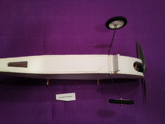
This shows the FT LG slot rear & the forward slot that I provided in the version 2 Completed plane with GensAce 3S 1000mAh: 563.9g or 19.89 oz.
Wing area (293 sq.in) loading: 9.77 oz./sq.ft.
Dowels glued in and ready to fly. May 19 Well it wasn't quite ready to fly. I'd forgotten to check the prop clearance with the nose. I checked it last night and had to shave a bit off each fuselage side at the nose to clear the prop. The firewall is not in the actual position, as it is the firewall from the V2 version. The height is incorrect as well, just fitted to give it a try and see where I need to go from here. Going to annotate my V3 plans with some important notes now. I'm going to balance the props I bought at Nankin today. No flying weather in sight. Rats. May 20 Doesn't look like another test flight is possible until Tuesday, maybe. Starting here
Back here
It looks like he wasn't pulling any "up" here. May 21 The Fuselage bottom has always come out slightly long. I redrew the bottom more accurately this morning. It also changes the fuselage side angles just very slightly, and I believe more accurately. The 'hang over' paper was decreased in width just slightly as well. Found an interesting post by the original poster in the RC Groups Foamies (Scratchbuilt) Discussion need help to fly my plane Nirup MS "Thank I guys I tried to fly it but it went up and crashed so I broke the model in the field and returned home." May 22 Charged GenAce & Dinogy batteries for possible test flight.
Downloaded Sr. Telemaster .jpg and calculated incidences. I found 3.8 degrees of positive incidence in the wing and 2 degrees of positive incidence in the horizontal stabilizer. The decalage being 1.8 degrees. 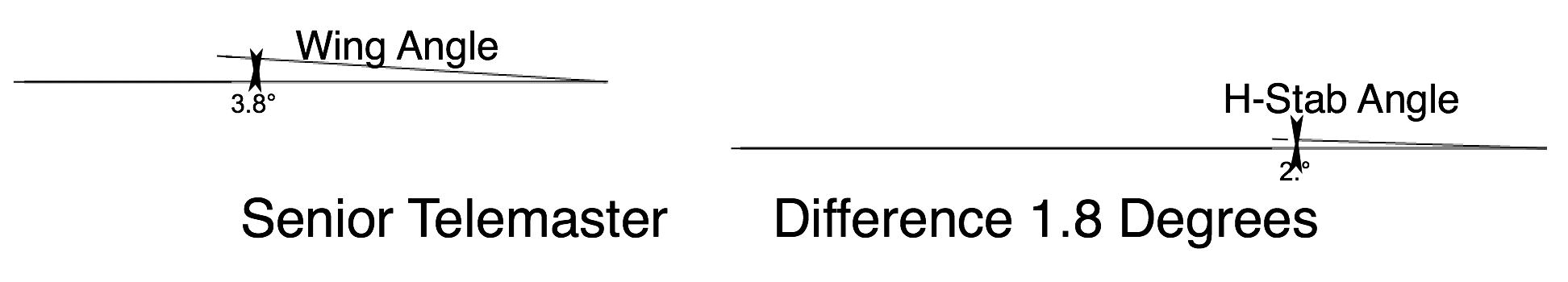 Flying was a bust. Both the 5 Mile and 8 Mile parks were too wet and the grass too long. I did find a path that might be useful on Thursday, at the 5 Mile Park, if the wind is from the right direction. I found the thread for the 3D printed servo mounts.
I am seriously considering going down in prop diameter. Even an 8x4E seems like it might be okay and it should stop the pull to the left on take off. The plane is way over powered at full throttle with the 10x5E. I have two 9x4.5E already balanced. I found two 8x4E props. One was balanced and I balanced the other. I need to check the Power Pod I'm using in the Fuselage V3. I think I may have too much down thrust. I believe I built in two degrees. Check my CAD drawing of the Firewall in V2. I just checked the V2 Power Pod, and IF that is the one I am using there is NO down thrust built into the Power Pod, only 1/2 degree of right thrust. May 24 The Power Pod angles checked out OK. Prop weights:
I have a terrible case of the "what ifs" this morning! Mostly, what if I am all wrong about everything? Arrived at the 5 Mile Northville Township park about 8:30 a.m. on a perfect morning for test flying with little to no wind. The version 3 fuselage had an APC 10x5E mounted to the motor. The GensAce 3S 1000mAh pack was placed as far forward as possible without hitting the rear of the exposed motor shaft. The CG was at 1.75" in that configuration. Flight 1: The Cub rose easily off the ground and required a bit of right rudder. It is absolutely NOT necessary, or desirable, to use full power on take off. The transmitter trims were all centered on take off, and no trim was added during the flight to any surface. The wind became 'noticeable' during the flight, but still very light. No aerobatics of any type were tried during the flight, just rectangles, both flying left and flying right and figure 8s. Full throttle was never given at any time during the flight. The glide slope was good and the landing was excellent with no flip. The power was completely off during the first landing. Flight 2: The prop was changed to an APC 9x4.5E and no weight was added to the nose to compensate for the lighter prop. I flew for a full six minutes, timed by the throttle timer on the transmitter. Several landings were made during the flight. All were good. I did try a touch and go, but flipped that landing. The APC 9x4.5E required only a little right rudder on take off. There was plenty of power in the air. I thought it might need just a tiny bit more of nose weight as it was 'squatting' on take off. I did check the CG after the flight, with the 9x4.5E on, and it was still about 1.75". Flight 3: I moved the Power Pod forward 1/4" to get the CG forward. Rich, Ken Johnson and I each flew the plane. We all had good flights, but none of us 'stuck' the landing and the plane ended up on its nose for each of us. Ken Johnson did have some trouble on his take off, as he went to full power. Flight 4: The GensAce was replaced by the Dinogy 70C pack positioned all the way forward. The Power Pod was moved back into its original position. I did four take offs and landings and all four landings nosed over. (I noticed after I got home that the loose landing gear problem showed up. That could have been part of the problem.). Roger flew the plane quite awhile, did a loop. His landing flipped also. Flight 5: Using the shims for the power pod, removing the shims for the H-Stab and moving the gear to the rearward position reconfigured the plane to the original Flite Test configuration. The CG was checked and still found to be at the FT recommended 1.75".
I also remember doing two loops on one of the flights. I forgot to note it. I didn't try to open them up, so they were pretty tight, but worked out well. Post Flight Thoughts
The gear still needs to moved forward some. How much is a real question; a 1/4" or a 1/2"? Roger thought that it could use a little less down thrust if flown as a 3-channel without ailerons. At home I checked the CG for the FT version and Dinogy 70C pack and found it to be 1.75". I measured the resting battery voltages of the GensAce and Dinogy 70C batteries when I got home. I was surprised. The GensAce, which had more 'on' time measured 3.79V per cell and the Dinogy 70C 3.75V per cell. The GensAce only flew in the plane using my incidences and the Dinogy 70C using my configuration and the FT configuration. I remember my impression while flying the FT configuration that it was taking more power to hold level flight, but that was only a subjective feeling.
May 25 I wanted to continue to fly the V3 fuselage.
I got the Cub back together in my configuration and it is in the car. If the winds are light, I plan of doing a little more testing. I tried at least four times yesterday to work on the final plans for the Cub, but I couldn't "get into it." It was bad, because I had the time to do it!!! Yes, I finally figured out how to get to work on the V4 version and started the latest drawings! :-) At the flying field: Flight 1: Almost no wind. Really long grass at the flying field. Probably 4 to 5 inches. The Cub actually 'leaped' out of the grass and into the air on the second try. Later, Dave Stacer got out the tractor and made a few swipes down the center of the runway so that the folks planes could take off.
Flight 2: Still almost no wind, but a little breeze could be felt during the flight. The Dinogy 70C pack was used. The flight was transmitter timed via the transmitter throttle timer. Dave Stacer also flew the Cub for a couple of minutes during this flight. I did plop it down on landing trying to land on the narrow mowed strip and it flipped in the long grass.
May 27 Continued to work on the new plans for Mike's templates for his kit built Simple Cubs and my new version. Rats, it just occurred to me to try flying it with the CG moved back to 2"! That would make a difference in the down thrust as well. For the CG at 2", the LiPo must be reversed. If it works okay, then the new Power Pod position for the strap is in the wrong place. Charging right now. Will pack up and leave for the flying field when the GensAce and Dinogy 70C are charged. They are parallel charging right now. The plane was set up using the 2" CG position by placing the batteries as far back in the battery compartment as possible. Flight 1 (9 a.m.) - Easily rose off of the center mowed section at Midwest. Really no wind. I called it calm at the flying field. I flew trainer like for a timed 8 minutes using the throttle controlled timer on Tx. It need a tad of left rudder, so I adjusted the clevis on the rudder before the next flight. It need a tad of up elevator, so I adjusted the clevis on the rudder before the next flight. I did 4 CG dive test from level flight and the CG appeared to be just slightly positive, which is good. Flight 2: The trim seemed better. Several more CG dive tests were performed. I did a landing about six minutes into the 8 minute flight. It flipped on landing. I did NOT flip on the landing ending the flight. Pretty much glided in, but I may have given a blip of throttle as it landed near me. I'm thinking that I should really try the APC 8x4E prop. I changed to that prop when I got home and checked the CG with the rearward battery position. It is still at 2". Very good. Before charging at home, the GensAce cells measured; 3.833V, 3.837V, 3.846V.
Before charging at home, the Dinogy 70C cells measured; 3.833V, 3.831V, 3.834V. That is almost identical to the GensAce.
May 28 Worked on V4 fuselage plans and changes for Mike's plane until the kids came over for breakfast. Continued to work on V4 fuselage plans and changes for Mike's plane after the kids came over for breakfast. I'm thinking I am done now, but I'll wait until morning to double check everything and be sure it is the way I want it to be. It is about 3:30 now and I don't do good work starting about this time in the afternoon. May 29 I am hoping to get all the parts ready for printing this morning for V4. I'll not make .pdf files only CAD files at this time for printing. That should save some time. I started thinking about order of assembly for my V4. Thought up a new idea for rear of wing reinforcement and protection from rubber bands. Created protectors for my new V4 version and for Mike's two planes. Worked on CAD and didn't get as far as I wanted today. May 30 I spent quite a bit of time looking for a specific crash video of the Cub yesterday. It shows a Cub crashing in slow motion for no apparent reason. I couldn't find it. I looked this morning on YouTube and it was the first video I looked at. The video is named: Flite Test Cub Maiden Flight
After the loop the plane goes into a high alpha and wobbles. Maybe a stall? It seems to fly okay for several more seconds and then the video switches to slow motion. It appears to go vertical with the lamp post in the foreground and then stall. It rolls to the right some, drops the nose and goes into a dive. Shortly after going into the dive it rolls left. I cannot see if up elevator is being applied. Unfortunately the plane goes out of frame during the last seconds of the crash. It is apparent starting here that the elevator has full up on it. During the several frames of slow motion the elevator position changes several times from full up to neutral and back. The author of the video notes that the landing was "a little hard". Also, "After replacing the propeller, the Piper flew again!" Another video called: My FT Cub Experience and Modifications Near the beginning of the video, note the wheels canted well forward and the tears in the fuselage side from the landing gear. Note here how far back the rear wing hold down dowel was moved. I am thinking of doing something similar as well. He tried a touch and go and it didn't work, went up, but didn't flip. He could not take off again. Landing at this point in video, flips on its nose. Bad landing here, but only dragged a wing tip. Disaster/kerfuffle/OMG! I opened the Turbo CAD file for the parts for version 4 (V4). The file had gotten corrupted. All of my fuselage work was GONE - not there - not anywhere! Several of the parts groups had somehow joined together without me doing it. It was totally useless. I spent the morning working on getting back the work that it had taken me two full days to do and making backups!!! I believe that I am back to the point that I can start to make the print files, maybe. May 31 Worked to get the V4 Parts2 completed and ready to create the files for printing. I had a lot of stuff to do this morning, so I had a lot of time to think about the plane 'hopping' off the ground with no ground run to speak of. I think that it hops off because it is setting at take off attitude. My original thought was to put a useful tail skid on it like on my RUA 2-4-10, but then when I finished up the V4 version I hadn't. Further thought convinced me to do it, so revised the V-Stab and rear bottom fuselage piece to have a 3/16" dowel tail skid. Finished up the modifications for the tail skid. I'll double check in the morning before leaving for Coldwater. June 1 I spent yesterday wasting my time on the tail skid. It was too complicated. I did a simpler version this morning, but it is visually unappealing. I did put it onto fuselage V3 to try at Coldwater tomorrow. It needs to be reconfigured to be more visually appealing. I checked the balance with the new tail skid on. While waiting for Chris to get her nails done so we can leave for Coldwater. What is wrong with the Simple Cub 1. The plane itself is poorly designed. The wing and horizontal stabilizer are set with zero incidence between them. In other words, there is no decalage, angular difference between the two. This causes at least three problems. With this configuration the Cub's decent is steep, with little glide. Unless landed perfectly under power, the Cub will flip over on landing. True touch and goes are almost impossible, but "bounce" and goes can be accomplished. 2. The landing gear position is too close to the CG, this also exacerbates the flipping on landing. 3. The landing gear wire, without the "optional" struts attached is pushed rearward upon landing, tearing the fuselage sides near where the landing gear is attached. 4. The landing gear tab design allows the landing gear wire to become loose in the tab after several landings. The landing gear then becomes wobbly in the landing gear tab. 5. The short tail moment makes the plane pitch sensitive. For all of the movable surfaces the recommended throws are 12 degrees, which is about right for a low time or no time pilot to attempt to fly this plane. The FT control horns are too short to allow 12 degrees of throw to be set mechanically. The DIY build video shows using a computer radio to set the throws and dual rates. Exponential is also given for this plane. Setting up a computer radio is an advanced and learned skill, not a beginner skill. 6. The plane sits on the ground at a very high, 18.3 degrees, angle of attack (AOA). When power is applied, the plane immediately leaps off the ground at a low speed, with a high AOA, which can lead to a stall if some down elevator is not briefly applied. 7. Affixing the servos to the fuselage side with hot melt glue is handy for setting the control surfaces to neutral. Unfortunately, the bond between the foam board and servo is "iffy" at best. 8. The recommended wire pushrods for the elevator and rudder, based on the diameter used for the pushrod wires provided in the laser cut kit, are too thin for their relatively long, unsupported runs and can buckle under flight loads. The rods have to push for both up elevator and left rudder. 9. The plane is "over-powered" for a low or no time pilot. It appears that the power system was chosen for its weight to balance the tail with the CG at the FT recommended 1.75" from the leading edge of the wing. A two cell system would have worked, but it would take a large capacity 2S battery to achieve the balance. A large 2S pack is more expensive than a smaller 3S pack. A quick look at the FT store showed no large 2S packs are sold by FT. 10. FT recommends an 8x4.5 slow fly prop. Many people, including myself have tried 10" diameter props. There is a large P-factor pulling the plane to the left on take off with a 10" diameter prop. I used an APC 9x4.5E, and it wasn't too bad. I'm trying an APC 8x4E today. 11. The plane averages less than a 4 amp draw. That means it is requiring an average of 50 watts in or less for a 20 oz. 4-ch. version. This is also why I say that it is over-powered. June 2 (Coldwater, MI) Pretty good flying weather at the Balsa Butcher's flying field just outside Quincy. Flight 1: Dinogy 30C battery. I only flew for about 2 minutes. The plane was acting very, very squirrelly. It was almost uncontrollable. I landed and flipped. I attributed the controllability issue was due to the large sub-fin the tail skid was on. I removed the sub-fin and tail skid. Flight 2: Keith took it up. He noted that it appears to need more down thrust and right rudder. He also noted that the ailerons were drooping compared to the slope on the back of the wing.
Flight 3: Revo battery installed. Keith flew it and then I did for about a total of 8 minutes or so. I landed it without flipping it, but it did go up on its nose and then back down. Again, I adjusted the rudder physically to match the trim that Keith had in it. He noted that is sure doesn't fly like a trainer. He pointed out that the wing is not mounted 90 degrees to the fuselage. I figure a triangle on the side of the fuselage could help in that alignment. The vertical stabilizer is twisted so that even more right rudder is required. Flight 4: A-Spec battery installed. I flew about 6 minutes and flipped on landing. Once again I physically adjusted the trims. They should be good to go next time out. June 3 Keith called to chat about my RUA 2-4-10 trainer and other stuff. Again, he noted that he can't believe that FT is recommending the Cub for beginner's. The ailerons add an unnecessary complication. He notes that if feels like flying a plane with a much higher wing loading and that he almost 'lost it' a couple of times and had to work much harder to fly it than he felt he should have to. June 7 Flew twice today at Midwest. Light and variable winds. Good flying day. Both landings flipped even though they were really good. The gear is still not moved forward to the V4 position. At times the plane has a 'mind of its own' and heads in a different direction from the input. It is just flaky to fly as a 4-channel. I'm going to do some more 3-channel flights. Note: 07/24/18 Suffers from Adverse Yaw I really, really can't recommend it as a 4-channel plane at all. June 9 I got to thinking about why the plane has adverse yaw and looked it up online. One 'cure' is to mix the rudder with the ailerons, which I have already done to 15%. Maybe more would cure it. Also adding aileron differential should help; more up aileron and less down aileron deflection. That can be done with the radio mix or by moving the control horn rearward on the ailerons. This bears looking into. June 20 Worked on V4 some more. Made the Fuselage templates and turned into .pdf file. June 21 More on V4; finished templates and turning them into .pdf files. June 24 It appears that the dihedral gauge drawn on the plans and in the kit is too short to provide 5 degrees of dihedral per panel. I measured it this morning and it was only 4.4 degrees. See dihedral-angle-check.tc2
To get closer to 5 degrees, use 1-3/16" where bottom of flat surface wing ends, which is 13-1/8" from the center joint break. That would be 2-7/32" under the bottom of the tip across the at the high point of the airfoil. The FT dihedral gauge would need to be redrawn to reflect the change to 5 degrees and the new height up from the table. The above in red is inaccurate! The leading edge is 'pulled' up when the airfoil is created. I redid using the trailing edge measured out 12". I figured the angle on the FT dihedral gauge. It is 6.4 degrees. My original 3-channel wing is about 5 degrees. There is still a lot of work to be done here, but have to go flying now. In the afternoon: The 'top' of the rear 'spar' fold over really needs a 'notch' to allow the dihedral to reach the appropriate angle. The question is, "What is the appropriate angle?" The wing panel length from the center joint to the tip is 18.06445"
One problem is that the panels flex down after the gauges are removed. I need to get the tip just a hair over 2-3/8" at the bottom side of the high point. I can do that by using my ~1.5 x 1.5 wood, which is called 2x2. June 25 Obviously, I'd looked at the dihedral angle problem before, as I gave Mike the 2x2 wood I'd used. See April 12, 2017 - I noted the dihedral in that note. I reset the new 3-channel wing this morning. I'd cut it apart yesterday, as I'd used the FT 2" at line 8. I reset the Line 8 to 2-3/8" measured with a ruler and one of the 2x2s needed a shim, which surprised me some, but both tips have the measured 2-3/8" now, which is about 5 degrees. The almost 4 degrees (3.9) of the FT version should be okay, but it is just my opinion that 5 degrees is better. I wanted to fly the Cub with the 3-channel wing I made using the 2x2s (April 12) again yesterday, but the wind was too high for the little cub. Wing construction Note: IMPORTANT
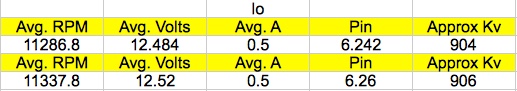
June 27 My latest version, V4, was coming along well until I realized that the doublers were not aligned correctly using the top straight line pin pricks. Cut a 1/2" wide 12" long piece of foam board and pin it to the inside bottom of the fuselage to help align the doubler. June 28 Flew two flights after mowing. The plane used the version 2 3-channel wing, version 3 fuselage used for testing the decalage angle and the 8x4E prop. It flies 'better' than the 4-channel version and, with no ailerons, doesn't suffer from adverse yaw. It still won't land without flipping on its nose, even on the freshly cut grass. The throws are set up to the least possible, servo arm innermost and long control horns outermost. I plan to experiment with more throw on the elevator on the version 4 3-channel plane to see if I can get it to land. Version 4 also has the landing gear moved forward again. Now it is 1” farther forward than the original. June 29 I did prop tests first thing in the morning. My procedures could have gone better. I'd forgotten that I'd left a battery charged from flying yesterday to use for prop testing today. I'd discharged it before I 'remembered', so had to charge again. Once charged, I did three run-ups using the 8x4E prop and then the 9x4.5E prop. I had looked at my Emeter and it said there were no logs. When I opened up the Emeter data in my Mac, I saw old .csv files. I should have ignored them and looked at the .log files and changed them to .csv files. I deleted all the data files before realizing that. I recharged the batter and collected the data for the 8x4E and 9x4.5E. Later I realized that my April testing was for the 10x7E and 9x6E props and did not include the 10x5.5E. I recharged the battery and did the 10x5E test. I continued covering the fuselage for the V4 version. I found a template for the windows in .pdf format on the Flite Test Form.
June 30 I drew up the side stripe, not Cub lightening stripe, in Turbo CAD. UNFORTUNATELY MY NOTES STOP HERE AND I DID NOT RECORD THE SUCCESS OF THE 3-ch VERSION 4! :-( I missed a whole lot of info on the tests flights of the Version 4. All went well, except I noted a bit of Dutch roll. Version 4 had its very successful maiden on the morning of July 7. Several flights, most likely 3 or 4 were flown. The glide path was good and it never once flipped on landing. I flew it again when Mike Russell and I went out to maiden his kit version. That was sometime between July 7 and 12. It flew well and did not flip on landing. Mike's 3-ch kit version with my version 4 modifications flew well and did not flip. Actually, there were two times that we went out early to fly. The first time it was too breezy for Mike to fly his kit version but I did the maiden on it. It did not flip on landing and flew well. We went out early the next day and he got to fly his first flights on it. The plane was flown during the morning of Sunday, July 15 at the mid-Am. The flight went well and the plane did NOT flip on landing. It was awarded the Most Unique NCM Aircraft award that day for the effort that went into making it fly correctly. July 25 I had Dave Stacer do take offs and landing with the Cub while I took video on my iPhone. He'd never flown the plane before. All take offs and landing were good. I created a video of two of the take offs and four of the landings and posted the video on YouTube. July 29 Flew V4 with added area on the V-Stab/Rudder. That eliminated the tendency to Dutch roll on take off. I also did an average amp draw check using the Dinogy 3S 1000mAh 70C pack.
August 1 Flew V4 again with the added area on the V-Stab/Rudder. Again, there was no tendency to Dutch roll on take off. I also did an average amp draw check using the A-Spec 3S 1000mAh pack.
August 3 Flew V4. I did an average amp draw check using the Revolectrix 3S 1000mAh pack.
August 4 (EFO monthly meeting) Flew V4. I did an average amp draw check again using the Revolectrix 3S 1000mAh pack.
August 7 Just noticed this afternoon that I have been flying version 4 with the pushrod in the outer hole of the servo horn, not the innermost. Oops!
August 8 Put both elevator and rudder pushrods in innermost holes of servo horns. Rudder is connected to outmost hole of control horn on rudder. Elevator is connected to 2nd from outermost hole on elevator. Rudder is now at 12 degrees and elevator is just shy of 16 degrees. Measured Great Planes Large control horns more accurately.
With the pushrod in the outer most hole of the servo arm and second from outermost hole of the control horn on the elevator, the full movement was 26 degrees. With the pushrod in the outer most hole of the servo arm and the outermost hole of the control horn on the rudder, the full movement was 16 degrees. I noted that the flying trim required some right trim on the rudder. I put that back in, after setting the transmitter trims to neutral for both elevator and rudder and measuring the rudder throw at neutral trim with no right rudder put in yet. I charged the GensAce 3S 1000mAh for possible use tonight at the Midwest meeting. August 9 Flew four flights last evening at the Midwest "Do Over" meeting. Flew as good as Mike's now with the rudder and elevator throw are correct. It was a beautiful evening for flying; sunshine, warm temperatures and little wind. I tried to get the flight time numbers from the GensAce pack, but the timer didn't start on the transmitter on the second flight. I charged the Dinogy 70C pack at the flying field at 2A, or 2C if you will. I did an average amp draw check using the Dinogy 70C 3S 1000mAh pack.
I flew the whole first flight. Dave took off and flew about 1/2 the second flight to try out the new control throw set up. Both flights consisted of circuits, a few loops, stall turns, many touch and goes and a lot of time doing horizontal 8s. August 11 Flew two flights with Cub. I charged the Dinogy 70C on the 9th to get mAh and left it charged. I did an average amp draw check using the Dinogy 70C 3S 1000mAh pack.
I flew both flights. The battery had been charged on the 9th so there was probably some self-discharged involved in the higher amp draw. Both flights consisted of circuits, a few loops, stall turns, some touch and goes and a lot of time doing horizontal 8s. August 18
I charged the Revo 60C at the flying field. I did an average amp draw check using the Revo 60C 3S 1000mAh pack.
|