 |
Flying High With Electric Power!
The Ampeer ON-LINE!
Fly the Future - Fly Electric! |
|---|
Site Table of Contents
| President: | Vice-President: | Secretary-Treasurer: |
| Ken Myers | Keith Shaw | Rick Sawicki |
| 1911 Bradshaw Ct. | 2756 Elmwood | 5089 Ledgewood Ct. W. |
| Commerce Twp., MI 48390 | Ann Arbor, MI 48104 | Commerce Twp., MI 48382 |
| (248) 669-8124 | (734) 973-6309 | (248) 685-7056 |
 | ||
| Board of Directors: | Board of Directors: | Ampeer Editor |
| David Stacer | Arthur Deane | Ken Myers |
| PO Box 75313 | 21690 Bedford Dr. | 1911 Bradshaw Ct. |
| Salem, MI 48175 | Northville, MI 48167 | Commerce Twp., MI 48390 |
| (313) 318-3288 | (248) 348-2058 | (248) 669-8124 |
| EFO Meeting: Wednesday, April 1 Time: 7:30 p.m.
Place: Ken Myers' house 1911 Bradshaw Ct. Commerce Township, MI 48390 Phone: 248-669-8124 Everyone with an interest is WELCOME | ||
| Simple Cub Construction Comment Owen Morgan comments on the idea of a battery protector for Ken's version of the FT Simple Cub. | Prop Noise and Thoughts on Prop Design Scott McKie shares some information on prop noise and points to some research that has been done on it. |
| An EXTREMELY Interesting Model Aviation Video Keith Shaw tells us were to find and extremely interesting video regarding model aviation. | Modifications to FliteTest's Simple Cub - Part 5 Ken continues his series on the what and whys of his modifications for the FT Simple Cub. |
| 2019 - 2020 Skymasters R/C Club Indoor Flying at the Ultimate Soccer Arenas Event Announcement & schedule | Indoor Flying Has Started at the Legacy Center in Brighton, MI Event Announcement |
| It's Time for Toledo - NOT! Event WILL NOT TAKE PLACE | The Upcoming Keith Shaw Birthday Party Electric Fly-in 2020 Event Announcement |
| Upcoming 2020 36th Annual Mid-America Electric Flies Event announcement. | |
From Owen Morgan via email Hi, Hope you are all doing well up there in the cold. Regarding the "battery protector" (shown) in your Simple Cub (in the March 2020 Ampeer), if a motor has a shaft sticking out behind the mounting plate, the first thing that comes out is my Dremel to lop that thing off. Otherwise it could puncture the battery in a crash and possibly cause a fire. This might happen if the crash is hard enough even if a battery protector is installed. Regards,
I 100% agree with you! The best "solution" is to mount a cutoff wheel in a Dremel and lop off the excess shaft behind the motor mount, but... I chose to use what I call a "battery protector" because this plane, at least in FliteTest's opinion, is aimed at a beginner, or near beginner, that may not have a Dremel. I thought that the "battery protector" was a "better than nothing" idea. I also used it on my RUA 2-4-10 trainer design for the same reason. I did have a student pilot test it for me in an RUA 2-4-10, and there was no damage to the battery, even though the nose was damaged a lot The "battery protector" is not THE best solution, but I believe it is better than nothing. Ken Prop Noise and Thoughts on Prop Design
Hi Ken, Great issue (March 2020) - - very informative. (Thanks, KM) Would you please wish Keith Shaw a happy birthday from me. He has been an inspiration to me for many years. About his Arrow being very noisy, it's because of the small number (three in this case) of blades mounted on the spinner. If they were replaced with a motor that had 9 to 11-12 blades (much narrower), I would bet that the sound level would be much lower and at the same time much more efficient with added thrust. The development of more blades on EDFs isn't for nothing. Keith Shaw volunteered. No one else volunteered, so a brief election was held, and Keith Shaw is now the EFO's vice-president. And another item that I think you guys at the EFO would get a lot of interest in is adding "fences" to the leading edge of both real and model propeller blades. Here's the history. Decades ago, I was researching how to increase aircraft propeller air movement efficiency, and I came across a report from the Ford Automobile company. The report stated that two young researchers had strongly attached 1 inch tall metal "fences", going from LE to TE, on the forward surfaces of all of the fan blades of an automotive fan; and then tested it for any efficiency increases. The fences were bent in an arc, again from LE to TE, so that they "curved" as they were spun on the revolving blades. What they were trying to do was to stop as much air from slipping off the end of each blade as it revolved and they started with fences in the middle of the blade. They hadn't yet attached more curved fences at the blade tips. As I remember the results, they got an increase of almost 50%, which was substantial, but nothing I know of coming from the research. I have asked many engineers, over the years; if they thought anything like adding "fences" to a plane prop would increase the propeller's efficiency, and was resoundingly chastised for such thoughts. Advance to the year 2020, with the big push to bring on electric power for powered flight in full sized aircraft - - which would also work on models. This month I read about a speed record breaking Long EZ build that had a special, hand-built, three bladed propeller; built by Craig Catto. The prop had fences added to the leading edge of each blade. So that you know, in the realm of hand / home built aircraft, Craig Catto is considered as being like "Merlin the Magician" in making good props. His props are a prized possession. If it's good enough to be found on a Catto prop, it's something. My point in all of this is that, with the advent of the Electric Beaver that will be flying into my home city of Seattle from Vancouver, British Columbia, the electric motor used is being built in Redmond, on Lake Washington across from Seattle, and all of the refurbished Beavers are done at the northern end of Lake Washington, these new fences would be something to look into. You have a bunch of guys that are really good at doing ground breaking research, and adding fencing to propellers, which could substantially increase battery powered flight times, I would think, would be very worth while. Anyway, there you have it. I hope you have people in your group that find the subject interesting, challenging, and will run with it. From Keith Shaw via email Keith recently shared a link to a very interesting model aviation video from "across the pond". The video is titled, "James May's Toy Stories: Model AIRPLANE across the SEA - Reel Truth Science". As Keith warned in the title of his email, "You guys will enjoy this, fill your coffee cup first". The video is just under an hour long, but I highly recommend it and feel that it is well worth your time to view it in its entirety! By Ken Myers Part 1 December 2019 Ampeer
Continuing My Modifications On the V2 and V3 versions, I used Fiberglass Filament Tape, NOT packaging tape, to wrap around the firewall and power pod as shown in the FT build video. The V4 version has no tape and the firewall and motor are staying on the plane just fine. 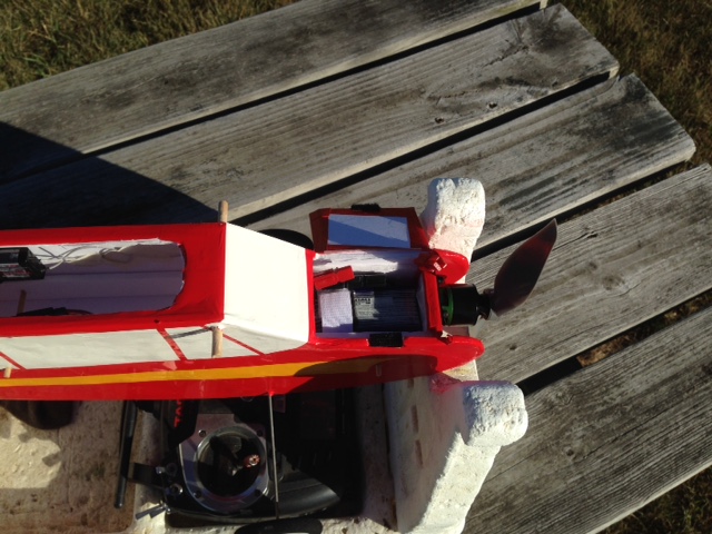 Slits were cut along each side of the power pod to insert a Velcro strap to wrap around the battery. This links to an FT video that shows why a strap for the battery is a good idea. If a battery strap is not used, there can be an unwanted battery loss in flight, as shown in this video. 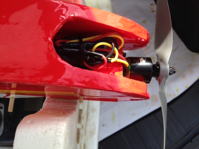 A hole was created in the floor of the power pod, behind the hatch area, to allow the ESC's battery connector to pass through. The ESC was attached with Velcro to the bottom, front of the power pod. Velcro is used to attach different ESCs to the power pod. Two different ESCs were used on the prototypes. A Cobra 22A ESC with 2A Linear BEC was used for the 3-ch versions with only 2 servos. A Cobra 33A ESC with 3A Switching BEC was used when the 4-ch wing, with two more servos was used. Flight testing showed that to attain the proper CG, the battery needed to be placed all the way forward in the hatch, so V3 and V4 had the connector hole through the power pod floor behind the hatch area. 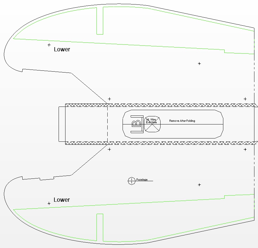
The Front of the Fuselage Modifications The front fuselage top was cut off at the point where the windscreen ends on the original plan. The top front was cut down for the fuselage hatch to fit flush across the top and a notch was placed in the right side for a Velcro hatch closure. The point where the power pod hold in enters the fuselage was lowered to come across the top of the power pod in its new position. A rectangular hatch was made to fit across the front of the fuselage. It is secured on the left side by fiberglass filament tape and on the right by Velcro on the hatch and in the right side, front fuselage slot. The link to this part of the FliteTest build video indicates that the Simple Cub was intended to include a top hatch. The foam board landing gear tab did not hold up well for me in V2 and V3. The wire landing gear legs became wobbly and loose in the tab. The wire also was pushed back into the fuselage sides because of the less than perfect landings. 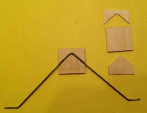 The V4 version uses a landing gear tab made from 1/8" and 3/32" plywood. The 1/8" plywood is on the outside of both of the tabs. The 3/32" plywood was cut accept the 3/32" music wire I used for the landing gear legs.Th e whole unit was laminated together using Aleene's Original Tacky Glue to attach the 3/32" pieces to the 1/8" pieces and then those laminated pieces were joined using epoxy, with plenty of epoxy in the trough for the legs. The 1/8" plywood laying under the landing gear legs keeps the landing gear wire aligned in the slot in the new, plywood landing gear plate. 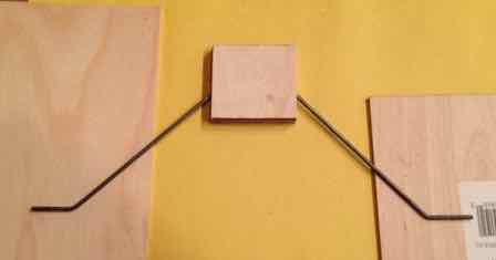 The unit has held up well. Each of the axles on the landing gear legs was bent slightly forward. This provided toe in for the wheels. The toe in allows the plane to track straighter on the ground. Flite Test recommended the Power Pack B for this plane in their store, at the time this was originally written. At that time, Power Pack B contained an EMAX MT2213-935KV multi-rotor motor and BL-Heli 20 amp (XT60 connector) ESC. That link now points to the new Power Back B which includes a Radial 2212-1050kV motor and Flite Test 35A ESC w/XT-60 connector. The original Emax MT series was designed for use on multi-rotor frames. The Emax MT series did not contain a cross-mount, for mounting the motor to the outside of the firewall, which is a more typical mounting for model airplanes. To affix the motor to the plywood firewall, screws are inserted through holes from the back of the firewall into the back of the motor on the front of the firewall. The motor was listed as the MT2213-920Kv on the Emax Website, but the Kv was stated as 935. A problem using this motor in the Simple Cub was reported in the FliteTest Forum thread "Scatch Building FT Simple Cub - 2213 motor too short". User pjmills81 posted a question and photo that shows that when the power pod was fully inserted into the Simple Cub, the prop hit the front of the fuselage. 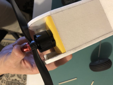 User checkerboardflyer posted a photo showing the Power Pack B motor mounted to the firewall compared to the Power Pack C motor mounted to the firewall. 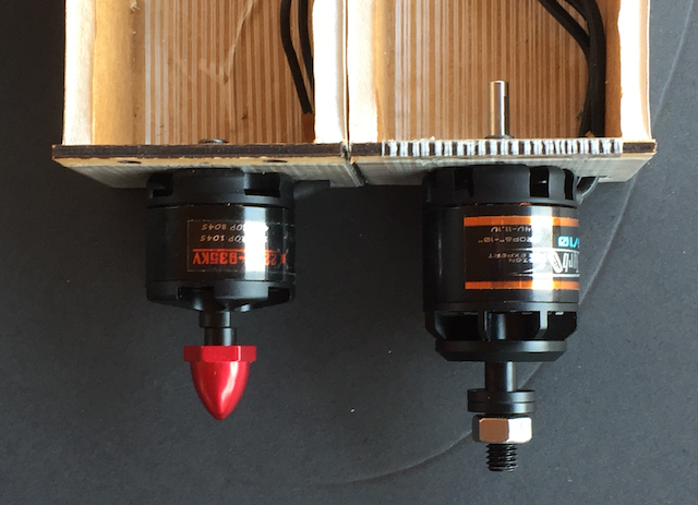 The motor on the left in the photo is the Emax MT2213-920Kv and the one on the right is the Emax GT2215/10-1100Kv. It can be seen that the motor 'body' of the 2213 is shorter than the 'body' of the 2215. The numbers used by Emax, to identify their motors, is the stator size. The larger, GT2215/10, was the motor that Josh Bixler actually installed in the DIY build video for the Simple Cub. When Josh turns the box sideways while opening it, it can be seen that it says "GT2215-10" on the side of the box. What I found interesting is that the actual Emax Website does not list a "10" or its stated Kv of 1100. Only the /9 with a Kv of 905 and the /12 with a Kv of 1180 are listed. The same data, that was found on the Emax Website, was parroted on the Flite Test Website. That page has since been removed from the store's Website. A Google search yields a number of suppliers selling the Emax GT2215/10. Obviously, it does/did 'exist'. The Emax MT2213 has a listed length of 39.7mm and weight of 53g. The GT2215, in the diagram and table found on the Website page, shows a motor length of 33.5mm and weight of 70g. It is obvious, from the mounted side-by-side photo that the GT2215 is longer. It appears that the length of the MT2213 includes the prop adapter. My GUESS is that the weight listed also includes the prop adapter part of the motor and not just the motor itself. I wanted to use a Cobra motor, as they are my "go to" brand. Outrunner motors with approximately the same weight and Kv are quite similar in performance and can usually be substituted for each other. Since I was not aware that the 53g weight of the MT2213 was most likely the weight of the whole, ready to use, unit, I looked for a Cobra motor of about that weight and about 935Kv. I found the Cobra C-2213/26 had a stated weight of 61g and stated Kv of 950. That was close enough for me. Cobra also uses the stator size to identify their motors. I was able to use the C-2213 with the power pod pushed all the way to the rear stop on the fuselage doublers with this motor, although props with large pitches would hit the front of the fuselage. That is really not a problem as this plane works best with 'low' pitch props. This Cobra motor comes with a cross-mount and bolt-on prop adapter. Ready to use, with the prop adapter and cross-mount installed, it weighs 68g or 2.4 oz. In the end, and after a lot of glide testing and CG recalculations, it turned out that the Cobra C-2213 might be too light. During the original build, Josh Bixler used the "C" motor, the Emax GT2215. It has/had a weight of 70 grams, plus the screws, cross-mount and prop adapter. A Cobra C-2217/20 960Kv motor was installed in the final, V4, version of My Flitetest Simple Cub to add a bit more nose weight. The Cobra C-2217/20 weighs 73.6g/2.6 oz. With the accessories it weighs 82g/2.9 oz. Those weights are very much inline with the GT2215. A Cobra C-2217/20 was tested using a Cobra 22A ESC and Dinogy 3S 1000mAh 70C LiPo. An APC 8x4E and APC 9x4.5E were tested. A ready to fly weight of 21.6 oz. was used to create a power to weight ratio (Pwr 2 wt) in watts per pound. 
Specifications: General:
Wing: 5.42 oz./153.57g Fuselage No Battery): 12.38 oz./351g Six #33 rubber bands: 0.11 oz./3g Completed Airframe Total: 17.91 oz./507.75g Note: The Econokote covering on the wing added about 39g or about 1.4 oz. and about 33g or 1.2 oz. to the fuselage and tail feathers for a total weight gain of about 73g or 2.6 oz. A-Spec 3S 1000mAh w/Velcro & Tape: 95g RTF Weight: 21.26 oz./602.75g Wing Area Loading: 10.45 oz./sq.ft. Wing Cube Loading Factor: 7.32 [That value is on the low end of the typical sport type range.] Version 1 was never flown. A 3-channel version 2 was first flown on April 26, 2018. I noted that it landed on its wheels and flipped and that it needed some right thrust. Several modifications were made and it was flown again on the April 27 to check the CG. Version 2 was flown again on April 29, but with the 4-channel wing attached. I noted that the number 64 rubber bands were pulling down the wing center section and "lifting" the ailerons. Adjustments were made and it was flown with the 4-channel wing on April 30. It felt extremely pitchy and sensitive to CG changes. The landing gear tab was failing. I felt that it would benefit with having some rudder mixed in with the ailerons. Starting on May 2, I did a series of glide tests in the side yard, trying to discover why it always nosed in, even though it was not technically nose heavy. Based these tests and a lot of research the horizontal stabilizer decalage was changed. On May 7 I noted, "Nothing I'm doing seems to be making the plane fly decently." Version 3 was created with an adjustable horizontal stabilizer incidence. Version 3 also featured 2 slots for the landing gear placement. Through the rest of May, many adjustments were made to the wing's angle of incidence, stabilizer's angle of incidence and the CG. By May 27 I had enough data to start the final version, Version 4. The final version was ready for flying at the July 14 and 15, 2018 Mid-America Electric Flies. It was awarded the Most Unique NCM Aircraft award that day for the effort that went into making it fly correctly. On July 25, I had Dave Stacer fly the plane while I took video. From the video, I discovered that it did have a bit of Dutch Roll, which I corrected by adding area to the front of the vertical fin. Because of the low current draw during training type flying, I can easily fly two seven minute flights on a 3S 1000mAh LiPo. 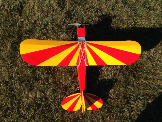
(Part 6 next month) 2019 -2020 Skymasters R/C Club Indoor Flying/Driving at the Ultimate Soccer Arenas The Best Indoor Flying Venue Anywhere!
Located at 867 South Blvd., Pontiac, MI 48341 October 29th through April 14th
Spectators Welcome and FREE
Single Flying Session ONLY $10
Pay at the door or register online at:
Have Any Questions?
All Pilots MUST Have Proof of Current AMA Membership
* Consult the Schedule on the Skymasters' Website for Exact Times and Dates Indoor Online registration is open at: www.skymasters.org. Schedule MARCH: (Suspended until further notice)
APRIL: ???
Dates & Times Subject To Change. Please note that a special area is set aside for electric RC Drivers. Did you note that Driving was added to the title? Costs and dates are the same for drivers as fliers. Indoor Flying to Start Soon at the Legacy Center in Brighton, MI Start Date: Wednesday November 6 Time: 12 p.m.- 2 p.m. Place: Legacy Center Sports Complex 9299 Goble Dr, Brighton, MI 48116 Cost: $10 cost per session Don't let the cold keep you from flying For More Information Visit the Hamburg Flyers Website. Return to "What's In This Issue" It's Time for Toledo - NOT! The Weak Signals' RC Model Expo, AKA "The Toledo Show", always took place at the Seagate Centre in Toledo, Ohio. It WAS scheduled for April 3rd through 5th. For current health concerns, IT HAS BEEN CANCELLED! The Upcoming Keith Shaw Birthday Party Electric Fly-in 2020 The Balsa Butchers are hosting the "Keith Shaw Birthday Party Electric Fly-In", for the 18th year, at their field near Coldwater, MI. The event takes place on Saturday, May 30, 2020. It is a one day event again this year. The event consists of Open Electric Flying with a "Special Guest of Honor Theme", Happy Birthday Keith Shaw [June 6]. Enjoy a day with the "Pioneering Master of Electric R/C Flight". 8 a.m. - 5 p.m., Saturday. NO LANDING FEE! Donations for field maintenance and lunch appreciated. For additional information contact;
The field will be open for guests to fly on Sunday as well. 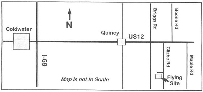
Return to "What's In This Issue" Upcoming 36th Annual Mid-America Electric Flies 2020 AMA Sanctioned Event (Proof of AMA/MAAC membership required to fly)
Saturday, July 11 & Sunday, July 12, 2020
Hosted by the:
Registration: 9 A.M. Saturday
Pilot Landing Fee - 18 and over, $10 for both days, Under 18, FREE (AMA/MAAC membership required)
Awards on Saturday Only
Planes Must Fly To Be Considered for Any Award
The Field is Open for Open Flying All Day Friday
Come and join us for two days of fun and relaxed electric flying. The NCM (Not Conventional Materials) Event
Foam Flurry for NCM aircraft
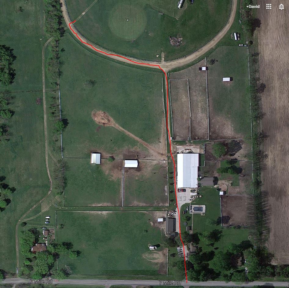
The old entrance to the Midwest RC Society flying field is permanently closed!!! DO NOT ATTEMPT TO USE IT!!! To locate the Midwest R/C Society 7 Mile Rd. flying field, site of the Mid-America Electric Flies, look near top left corner of the map, where the star marks the spot, near Seven Mile Road and Currie Rd.
Entrance to the flying field.
Because of their convenient location and the easy drive to the flying field, the Comfort Suites and Holiday Inn Express in Wixom, MI have been added to the hotels' listing. They are only 10 miles northeast of the field and located near I-96 and Wixom Road. See the map-hotel .pdf for more details. Return to "What's In This Issue" To Reach Ken Myers, you can land mail to the address at the top of the page. My E-mail address is: KMyersEFO@theampeer.org |
