11th Annual Fort Wayne "Electri-Fly"
By Ken Myers
August 11th, 2007, 8:00 am start, fly all day. Join us for a day of great flying at a fantastic field. Field improvements this year include new, permanent shade shelters! Hundreds of dollars worth of items will be raffled off. Landing fee of $5.00 is asked, ALL PROCEEDS will go towards continuing improvement of this great field and clubhouse.
Food and drinks available from our kitchen.
Go to www.flyingcircuits.org for maps or other information. Pat Mattes (260-478-7302)
Electrics Over White Lake
August 19 Pontiac Miniature Aircraft Club, PMAC's flying field is located in the Pontiac Lake Recreation Area in White Lake, Michigan on White Lake Rd, 0.55 miles east of Teggerdine Rd and about 1 mile west of Andersonville Rd., CD Sterling Smith smitty559@comcast.net or visit www.pmac.us
Upcoming Cedar Rapids, IA Fly
On August 18 and 19 an Electric Fun Fly is scheduled in Cedar Rapids, IA. It is presented by the Cedar Rapids Skyhawks. You are invited to come fly with them for 2 days of electric fun at the Skyhawks field in Cedar Rapids, Iowa. They will have a 500 ft. fabric runway, good field food and it's only $10 for the whole weekend! For More Information visit www.crskyhawks.org and check the events page. CD Contact information: Kerry Lawrence, Phone: 319-390-3570, E-mail, kerrylawrence@mcleodusa.net
Return to "What's In This Issue"
Timing Test
By Ken Myers - July 2007
For a long time now, the correct timing to use for brushless outrunner motors has been a problem because of all of the conflicting information available in both the print media (magazines & instruction sheets packed with ESCs) and the Internet.
Advanced timing was used on some brushed motors for "Sparkless Commutation". On high performance brushed motors, like the Astro Flight cobalt FAI motors, timing was advanced for an application where high amperages were to be drawn for most of the time when the motor was on, and partial throttle was not going to be used. F5B and LMR were two common aircraft applications, while car and boat drag racing were another. Advanced timing was used in these high amperage applications because as the power increased beyond a certain point, trailing edge "fire" appeared along the trailing edge of the brush and caused burning on the trailing edge of the commutator. This "fire" caused the positive brush to wear twice as fast as the negative brush.
According to Bob Boucher in his Electric Motor Handbook Chapter 3 "Timing for Sparkless Commutation", "Over advancing motors is commonly done in racing motors where maximum power and maximum speed are all important. Over advancing a sport motor will cause excessive heating and failure if the motor is run at half throttle or less. Don't over advance the motor in a sport model where you intend to fly at half power much of the time."
Please carefully read and think about those three very important sentences!
With brushless motors, all of the commutation, including the timing, is done in the electronic speed control (ESC) not the motor. The brushless ESC manufacturers SHOULD be the ones to know how to best use their products with different types of motors, but�
Castle Creations appears to have no information on their Web site about timing, other than what is in the instruction manuals for each brushless controller. Here is what is in the manual today for the Phoenix-45. (It wasn't always this recommendation!).
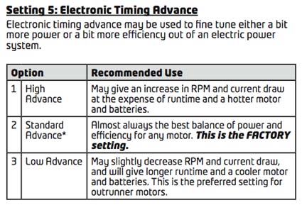
Carefully read the last sentence in the Low Advance section.
The FAQ (frequently asked questions) on the Castle Creation site contains no information about timing. It is actually hidden here.
The following is my edited version of the paragraphs that Castle Creations has on the Web page noted above.
"Special Note on Timing Advance:
Timing advance in brushless is controlled within the ESC itself instead of rotating the endbell on a brushed motor.
What you'll find when you experiment with timing advance settings, is that going up or down from the normal setting will cause two reactions. With each step down from normal, your motor temp will go down and the top speed will go down about the same as dropping a tooth on the pinion. Going up, it's just the opposite - it's like adding a pinion tooth, but the motor temp will go up. (Obviously aimed at the car guys. KM)
Over time with testing, we've found it's best to use a lower setting in order to keep motor temps in check, especially with very, very fast setups.
Higher advance makes the motor run hotter, and the higher the Kv of the motor, the hotter it will get! Too high of an advance setting will give the same results as too much advance on a brushed motor - you will actually LOSE power and speed while the motor cooks itself!"
It would be really nice if Castle Creations added a FAQ about the effects of timing on inner-runner and outrunner motors, high and low Kv, winds and types of motors.
Here is some timing information for a Hacker ESC.
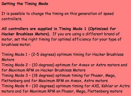
Note that the Timing Mode 1 is most likely referring to the B Series inner runner Hacker brushless. You can see they are recommending 30-degrees on outrunners.
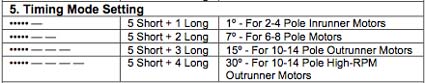
And still another one is the Welgard 65-amp instructions.
A quick review is in order;
Castle Creations - low advance
Hacker reference - 30-deg
Welgard - 15-deg or maybe 30-deg
Searching the Web will provide even more confusing information. Many times I've seen that outrunners should be timed with 30-deg advance, and equally as many times a 15-deg advance.
So what is it? There was only one real way to answer that question, and that was a test.
I still had my BP/TowerPro 3520-7 on the test stand, along with the Welgard 65-amp (now discontinued and replaced by the BP 60A Brushless ESC for only $24.95!).
On Monday, June 25, 2007 I ran a series of tests to answer the following questions.
What happens to the Io when the timing is changed?
What happens to the Kv when the timing is changed?
What happens to the Rm when the timing is changed?
What happens to the current when the timing is changed?
What happens to the RPM when the timing is changed?
What is the best timing for me to use with a BP/TowerPro 3520-7 outrunner?
The timings available on the Welgard 65A in degrees are 1/7/15/30. The temperature through the 5-hour testing period ranged from 84F to 90F, with the barometric pressure about 30.15 in. and humidity in the mid-40% range.
The testing was done just inside of my garage at the garage door opening facing north, while the rear entry door of the garage was left open for some airflow. The battery for the prop testing was my 6S1P M1 pack from www.bigerc.com at ambient temperature and recharged after each round of testing, as described in the July 2007 Ampeer.
Io has always been considered a constant, but is it?
10-cell Sanyo RC 1700 NiCad
1-deg Average: 12.808v, 1.76 amps, 7836 RPM
7-deg Average: 12.864v, 1.76 amps, 7908 RPM
15-deg Average: 12.946v, 1.88 amps, 8064 RPM
30-deg Average: 12.966v, 2.42 amps, 8568 RPM
4S1P Skyshark 4000mAh 10C Li-Po
1-deg Average: 16.122v, 2.00 amps, 9864 RPM
7-deg Average: 16.115v, 2.075 amps, 9900 RPM
15-deg Average: 16.145v, 2.125 amps, 10050 RPM
30-deg Average: 16.112v, 2.66 amps, 10584 RPM
Io goes up with the timing advancement. This was NOT an unexpected result, as it also does with brushed motors when the timing is advanced! Conclusion, Io cannot be given for a brushless outrunner as part of the "motor" data as it is dependent on the ESC design and manufacturing and how the end user sets the timing.
Please note that the real power out is a very "iffy" calculation without a dyno. The number indicated here for Power Out (Pout) is based on my best guess using my spreadsheet data and some prop data. Please don't assume that this motor is as efficient as it appears here, but since the same type of calculation was used to figure Pout, the relative numbers will remain pretty much the same
APC 10x7E
1-deg Average: 18.242v, 22.32 amps, 10176 RPM, Pin 407, Pout 332, eff. 81.6%
7-deg Average: 18.280v, 23.20 amps, 10224 RPM, Pin 424, Pout 337, eff. 79.5%
15-deg Average: 18.242v, 23.74 amps, 10302 RPM, Pin 433, Pout 344, eff. 79.4%
30-deg Average: 17.898v, 27.02 amps, 10572 RPM, Pin 484, Pout 372, eff. 76.9%
APC 11x7E
1-deg Average: 17.936v, 29.00 amps, 9708 RPM, Pin 520, Pout 422, eff. 81.2%
7-deg Average: 17.916v, 29.18 amps, 9726 RPM, Pin 523, Pout 424, eff. 81.1%
15-deg Average: 17.906v, 30.06 amps, 9810 RPM, Pin 538, Pout 435, eff. 80.9%
30-deg Average: 17.488v, 33.58 amps, 9996 RPM, Pin 587, Pout 461, eff. 78.5%
APC 12x6E
1-deg Average: 17.824v, 31.80 amps, 9516 RPM, Pin 567, Pout 457, eff. 80.6%
7-deg Average: 17.796v, 31.80 amps, 9546 RPM, Pin 566, Pout 461, eff. 81.4%
15-deg Average: 17.746v, 32.86 amps, 9594 RPM, Pin 583, Pout 468, eff. 80.3%
30-deg Average: 17.256v, 35.92 amps, 9738 RPM, Pin 620, Pout 489, eff. 78.9%
APC 13x6.5E
1-deg Average: 17.376v, 39.96 amps, 8886 RPM, Pin 694, Pout 550, eff. 79.3%
7-deg Average: 17.230v, 40.18 amps, 8850 RPM, Pin 692, Pout 543, eff. 78.5%
15-deg Average: 17.238v, 40.98 amps, 8940 RPM, Pin 707, Pout 560, eff. 79.2%
30-deg Average: 16.444v, 43.96 amps, 8886 RPM, Pin 723, Pout 550, eff. 76.1%
If Kv were a constant, then the highest voltage in with the lowest amp draw should produce the highest RPM, but actually, when the timing is advanced, the highest advance produces the highest RPM with the lowest input voltage; therefore the Kv must be relative and not absolute. Relative Kv is changing with the timing. Therefore, the Kv number given by a motor manufacture is a relative number and once again will be determined by the specific ESC and timing chosen by the end user.
What happens to the Rm (apparent motor resistance)? Unlike a brushed motor, the brushless motor will not run without the ESC to do the commutation. Thus, the ESC is actually a part of the motor and any Rm number given by a motor manufacture is pretty useless as it is only one part of the actual brushless motor.
While the motor Kv can be derived using the drill press method, once the ESC is factored into the motor equation, everything changes. One way to find out how the Rm, which I now like to call the motor/ESC relative resistance (Rme) is affected by the relative Kv is to do a quick and dirty relative Kv calculation.
Using the no load data from above, here are the quick and dirty relative Kv calculations. Note that these numbers are all slightly higher than the real Kv, but close enough for a comparison.
1-deg 7836 RPM /12.808v=611.8 relative Kv
1-deg 9864 RPM /16.122v=611.8 relative Kv
7-deg 7908 RPM /12.864v=614.7 relative Kv
7-deg 9900 RPM /16.115v=614.3 relative Kv
15-deg 8064 RPM /12.946v=622.9 relative Kv
15-deg 10050 RPM /16.145v=622.5 relative Kv
30-deg 8568 RPM /12.966v=660.8 relative Kv
30-deg 10584 RPM /16.112v=656.9 relative Kv
Using the relative Kv the output volts can be estimated, and that voltage can be used to calculate the relative Rme using the voltage drop and amp draw for the various prop runs. When this is done, (I'm not showing it here, but I'll be happy to provide my spreadsheet to anyone interested) it can be seen that the relative Rme goes down as the amps go up within any timing setting and that the relative Rme also goes down as the timing is advanced.
Since the simple and most used way to predicted brushed motor performance is based on the Io, Kv and Rm being constant, it is easy to see why those constants fail when predicting outrunner brushless performance.
I have been advocating the use of Drive Calculator for predicting motor/prop performance, because it is NOT based on Io, Kv and Rm being constants!
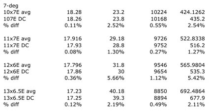
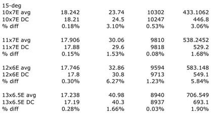
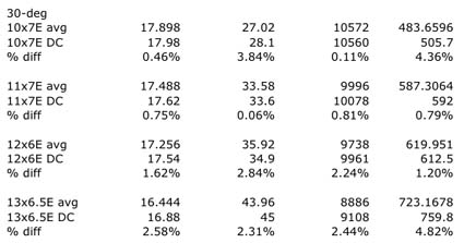
Here is why I believe in the performance predictions of Drive Calculator (www.drivecalc.de). The following shows my measured data compared to the information output by Drive Calculator. Remember that Drive Calculator has to take into account all of the changing "constants" of the motor and ESC, as well as what is going on with the power supply, in this instance a 6S1P M1 pack and manipulate the prop data and arrive at a prediction. You be the judge. (avg is my actual measured average and DC indicates the Drive Calculator Prediction. The numbers are presented in this order; volts in, amps, RPM and Watts In)
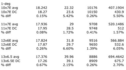
Low timing should provide the power and efficiency I want when I use this motor and help keep all parts of the power system quite "happy."
Update: A new version of Drive Calculator should be available by the time you read this. www.drivecalc.de
Remember that the program can be run using the Mac or Windows operating systems! Just select the version you would like to use.
Return to "What's In This Issue"
Upcoming EFLIOWA
From Orville Shields osrs73@yahoo.com
Hi Ken and Keith,
I haven't emailed you in a long time but I have followed your great newsletter for years and years.
Jon McVay has been sending you a notice about our electric fun fly each year for the last 9 years. Well, this year is our 10th annual EFLIOWA. It will be on September 8 and 9 at the same location in Davenport Iowa right near Interstate 80. I will be the new CD this year, as Jon would like to pass the baton on this one. I told him that I would take over the job if he promises to come and enjoy himself too.
Back in 1998 it was started as a gathering of likeminded electric power enthusiasts exchanging information and ideas on methods of powering R/C models quietly. It is now a reunion of old friends that share a common interest in this great hobby. By the way has anyone noticed that electric power is here to stay? Maybe it is the future!
We will continue with the same successful formula of no pressure flying and story telling from early in the day until everyone gets tired. As usual, we welcome vendors and swapping. We also welcome newcomers looking to get into the hobby to visit and ask questions.
There is a $15 landing fee for the weekend that makes you eligible for a prize drawing. We require AMA insurance for all pilots and HyVee will setup for lunch on both days.
The event should be in next month's Model Aviation and my contact information is in there.
Best Regards,
Orville
Return to "What's In This Issue"
1970's Freshman Trainer Updated to E-Power
From Ralph Brehmer reb4019@netscape.com
Hey Ken,
I used to live in the Detroit area and among a slew of other model clubs I allied with, my brother Bill and I belonged to the Livonia Ribcrackers probably back in the '60s and '70s.. We used to fly U control, indoor and R/C. Seems to me the R/C field was on 6 Mile near Farmington.. For a time I was CD. I remember the name Joe Ziomek. I still have some of the Bonner and other escapements I used.
Now I live in Cape Coral, FL and belong to the R/Seahawks.. I fly mostly electric power now. My favorite is a 1970's Falcon 56 I built back then with an old geared Astro 05 on a 2100mAh Li-poly.

That's the Falcon 56 on the left
Also, my brother gave me an old partially built Freshman Trainer (also vintage 1970) that I recently finished. It has a new Astro 19 on 2100Mah Li-poly. I haven't flown it yet, maybe this week. You brought back a flood of model memories to this 76 year old brain of mine.
Freshman Trainer with E-Power
Thanks and Cheers,
Ralph Brehmer
Return to "What's In This Issue"
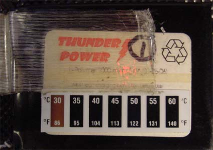
Battery Heat Indicators
From Jim Yuzwalk jjy@horseyfun.com
Hi Ken,
I thought I'd share with you a neat way to monitor in flight battery temperatures. I noticed on FMA Direct's website that they were using liquid crystal temperature strips on some of their battery packs. I thought this was a great idea, but the price per strip was a bit high. So, I went to Omega's website, www.omega.com, and did a bit of research. It turns out that they have some very nice temperature strips for a little over a buck a piece -- they are sold in packs of 10 for $12. Their model RLC-50-30/60-10 is a perfect fit for our hobby - small size, light weight, and correct temperature range. I'm now using one of these strips on each of my battery packs. They work great and the price is right.
Here's a link to the product...
www.omega.com/pptst/RLC-50.html
Best regards,
Jim
And a little P.S.
It was great to see you at the Mid-Am this past weekend. As usual the event was great. And many thanks to you and everyone that helped for putting on such a fine show.
As we discussed, I took a few photos of the temperature strips clearly showing their temperature range. Perhaps these will help a few fellow R/C flyers.
 Return to "What's In This Issue"
Bob Kopski on M1 (A123 Systems) Cells
From Bob Kopski
25 W. End Dr.
Lansdale, PA 19446
Hi Ken,
I agree with you. (Whew! ;-) KM ) I do think M1 cells are the way to go for sport flying! Your comment in the July Ampeer has prompted me to share some of my own A123 experience, as follows.
I have built six 4-cell packs (2 for a friend) and each "set" of two packs came from one 10-cell DeWalt pack leaving a total of 6 "spare" cells on the shelf. The three DeWalt packs were separate e-bay purchases from varied suppliers over time.
Having disassembled three DW packs so far, I can say with certainty that not all packs / cells are equals when first opened up. My first DW pack presented 10 cells that appeared to be very close in initial terminal voltage and indeed the resulting two 4-cell packs ("a" and "b") were / are well behaving. The second DW pack was different in that some of the cells therein were well low in initial terminal voltage but I continued on to build 4-cell assemblies "c" and "d" respectively. The third DW pack yielded cells similar to the mismatch in the above. Here again two 4-cell assemblies were built but I passed these on to my friend and have no follow-up data on them.
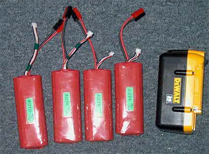
The packs and source
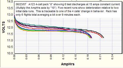
I took initial CBA data twice on all my four following assemblies. (I routinely do data runs "for the record" on all new batteries.) I chose a 15 amp constant current load and discharged to the pack voltage of 11.2 or 2.8V / cell nominal. (This test current was attained with my CBA Power Amplifier - Ampeer, May 2006) During test discharges I also monitor cell-by-cell terminal voltage with a DATAQ data acquisition module. Charging was via the 4S/A123 version. As of this writing packs "a" and "b" have 10 flights, "c" has 7, "d" has 6 - all spread randomly over two different planes / power systems.
The initial test bench data above showed fairly close behavior among the 4 packs. Two displayed about 2.1 AH and two displayed about 2.2 AH at cutoff. All subsequent flights had my Battery Discharge Monitor circuit (Ampeer, Nov 2006) on board set for 2 AH and upon landing / recharge NO pack displayed any depressed cell voltage among all 16 represented cells - until now.
For some unknown reason, pack "d" now has a "cell issue". I discovered this upon a routine test discharge (like the original ones) and found that this pack had an abnormal behavior in one cell - pretty clear on the DATAQ display. Basically, one cell displayed approximately 0.1-volt lower terminal voltage than the well-matched other three throughout the discharge, and the pack equivalent capacity was now about 1.9 AH due entirely this one cell dropping off quickly. I ran four more charge / discharge cycles (5 total) on this pack and got the same result.
I have no idea what happened to this single cell, given the essentially identical birth-use-history of these 4 packs. For now I'm going to call it "bad luck" but will now be watching all packs more closely from here on out. I'll continue to fly the 4 packs and pay particular attention to pack "d" for a while - up to where it truncates to become a "3-cell pack".
Despite this one "funny", I have a very warm feeling overall about M1 (A123 Systems) cells. They are a bargain when taken from e-bay DeWalt packs, are easy to re-assemble, and I very much like the apparent robustness they offer. I acknowledge they are heavier than the baggie Li versions, and generally have higher internal impedance than some of the latter, but overall I feel very comfy in the sport flying I do with this power source. I have another brand-new DW pack on the shelf ready to yield its contained treasure!
Since I very much enjoy my convergent hobbies of electronics and E-aero, I'm now toying with "converting" two older Astro 110D's to A123 charging via an "adaptor". This pursuit is totally without prejudice to Sid's product-in-kind; rather I just like playing with this stuff - for me this sort of thing is a lot of challenge and fun.
Hey - that's what a hobby is for, right? :-)
Happy E-Landings,
Bob Kopski
I asked Bob if he had tried to do any matching on the cells, and he came back with the following. KM
No - I did no "matching". I figured the 10 cells in a pack should work in a pack as in the originally intended application. Since I was making packs of 4 cells, I simply used the "end 4" from each pack yielding 2 blocks of 4 - each block's cells being already strapped in series. The two cells "in the middle" of the 10-pack then became "free floaters" - i.e. individuals.
As I wrote earlier, one 10 pack yielded well matched (in voltage) cells throughout, other DW packs did not - but in the end it did not seem to matter as best I can tell - when using the 4S charger. HOWEVER - I might imagine problems if a balancing charger were not used on these 4-cell packs that began life with mismatched cell voltages. I have not tested this and while it's been written (forums) that it's OK to just charge the whole pack - a lot has been written in forums that is questionable - don't you agree? (Yes, KM)
Since writing earlier I have taken 4 of those 2-cell leftovers and "bread boarded" a 4 cell array on the bench. Note the two "2's" originated in entirely different DeWalt packs and in fact they were VERY different in terminal voltage to begin with. I put this pack on the 4S which went into balancing at a low current as expected - it was clear this was going to take forever - so I reconnected them as sets of 2 (i.e. made pretend 2-cell packs) and charged these from the 4S. This went quickly. Then I reconnected this 4 pack to the 4S and it quickly shut down - since all cells were now "up to snuff".
I'm reasonably convinced that previously described "d" pack problem with one cell therein is (so far) a fluke.
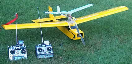
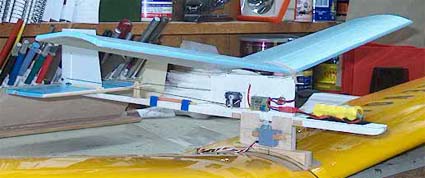
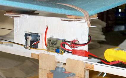
Attached photos are of my latest venture. I realize this is nothing new - but it works very well indeed. In fact, as an old free-flighter, I'm quite surprised at how well the little blue foamy glider works, the RC in it is so it does not get lost, in hindsight clearly a good move!
Bob
And More Follow-up from Bob
I spent today playing with an interface circuit to connect a 110D to my 4-cell A123 packs and I think I got it!
Again - I'm not prejudicing the LipoDaptor. I just like to play. The circuit monitors the total pack voltage (in this case it looks for 14.2 volts) and then opens the charging path. I tried a 110D, Triton, Dymond Super Charger, and a very old Astro 110XL. All charged at about 5 amps into the pack and the typical result was a discharge capacity of about 0.1 AH less than I'm seeing with 4S balancing charging.
I used that 4-cell "mixed" pack I wrote of earlier as the test case. It seems to work just fine despite it's quite-imbalanced origins. I still don't think I'd want to pour amps into an unbalanced pack without balancing or without balancing first - BUT - I've not tried it. (Maybe tomorrow!)
Bob
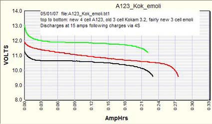
I don't know if I showed this graph before from Bob, but it is quite interesting. KM
 Return to "What's In This Issue"
2.4 Ghz in Europe
(Adapting the Futaba system to a Multiplex Evo)
Christen Persson cp@heise.de
Hi Ken,
I do not know whether you have covered 2.4gz RC in your newsletter yet. If not, it may be a good idea to do so. In my opinion, 2.4ghz surely is the future of RC.
I have purchased a Futaba 2.4ghz set and performed some practical tests during the last two weeks. The Futaba set that is available right now, is only 6-channel and lacks the features and comfort of the RC equipment I've gotten used to.
But meanwhile I succeeded in adapting the Futaba stuff to my Multiplex Royal Evo 12. I have added a 7th channel to the receiver, simply by adding a resistor they have left away. I'm using the Futaba transmitter board as an external module for my Evo. You simply plug it into the buddy connector. I have posted a description on RC Groups
2.4ghz technology is really a great thing: The frequency board is not needed any more, the devices deal with frequency overlapping in an intelligent manner. Full range, no glitches at all, fast response to sticks movements. You can read it in my words that I am very pleased with this technology.
Regards,
Christian
For those of you who may not read credits in computer programs, Christian is the designer and headman behind the Drive Calculator program. KM
Return to "What's In This Issue"
Mid-Am 2007 Thanks
Hi Ken,
Firstly, I do hope that your Mother has been able to leave the hospital and is now on the mend. You were very wonderful to have done so much for us, with this pressure on you.
Thanks for the kind thoughts. Yes, Mom is here at the house now (July 15, 2007) and seems to be doing better. I actually picked her up from the hospital right after returning home from the Mid-Am cleanup on Sunday. Thanks to everyone at the Mid-Am for your concerns and well wishes. KM
Thank you and Keith Shaw for putting on a very pleasant electric meeting. It was a lot of fun and I met many interesting and helpful people. Also there were many interesting projects.
Also thanks to the members of the Ann Arbor Falcons and Electric Flyers Only, who worked so hard so that we would have a fun couple of days.
The weather cooperated perfectly on Thursday evening and Saturday to encourage even the poorest of us pilots to fly!
I do enjoy your monthly Ampeer and appreciate all your hard work.
With best regards,
John Lewis
Congratulations John on your win of the Best Sport Plane on Saturday for your E-Venture 60. Excellent, excellent sport plane! KM
Return to "What's In This Issue"
Quotes With Comments - KM
Quite Flyer Magazine, 2007 Southeast Electric Flight Festival Report (Supplement) - "This beautiful 1/12-scale DC-3 was built and flown by Norman Frank. It flies on a 96-in. wingspan and to AstroFlight motors and a 300mAh battery."
Two for the money with this one.
Quite Flyer Magazine, August 2007, p80, "...The tail feathers need to be installed, and the design makes this step easy, but you should still do a trial fit to make sure everything aligns, as it should.
Test fit the tail feathers to ensure everything aligns too."
Okay, got ya the first time.
Quite Flyer Magazine, August 2007, p91, "During a rough landing on grass, the gear folded. Upon inspection, it appears the thin plywood is not quite strong enough to hold the gear in position."
Ya think?
Model Aviation, June 2007, p72, "The gear held up for roughly three landings before the bottom mount on the one leg broke."
Is this a trend?
Quite Flyer Magazine, August 2007, p81, "The MiniMag flies very nicely with good speed, but with the stock power system you need to be gentle with the climbs since the small propeller doesn't offer much 'grunt'. If you do try to climb too aggressively, the MiniMag will slow and stall."
Let's see, flies nicely with good speed but stalls in the climb. Keep your knees out of the way with this one!
Return to "What's In This Issue"
To Reach Ken Myers, you can land mail to the address at the top of the page. My E-mail address
EFO WEBsite:
|

