Jun-Si PowerLog 6S Review
By Ken Myers
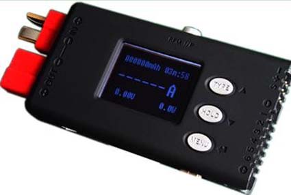
The PowerLog 6S is a very compact multifunctional monitoring and logging device. Its measured size of 80mm/3.15" long, 40.5mm/1.6" wide and 13mm/0.5" thick, combined with its low weight of 28.7g/1 oz., using just the T-PLUG connectors (similar to Deans) without its extra supplied input/output lines and connectors and 53.9g/1.9 oz. with the input/output lines with Anderson Power Pole connectors, allows it to be used as an in-flight data logger in appropriate size airframes.
One of its functions is to act as a typical, handheld power meter or wattmeter. Although the measured screen size of 25mm/0.98" wide by 14mm/0.55" high is much smaller than the typical power meter, it is still useful at the field for quick power checks. Another typical 'field check' is the propeller RPM, which can be accomplished with the optical Tachometer function. At $49.99, it does not cost much more than a typical power meter, and it is a tachometer as well. This makes it a good value. The cost of a power meter and a tachometer would typically be more, if purchased separately.
After reading through the manual once, which I had downloaded onto my Mac, I thought, "That's cool" and then, "Huh?" I really didn't understand what I had just read.
A 'better' way to get a quicker and better handle on using this device is to initially ignore anything to do with the alarms and alarm settings and the pulse width modulation (PWM), which is used with servo monitoring and testing. Ignoring them drastically cuts down on the amount of "information overload". The use and setting of the alarms and PWM may be learned when they become important to the user.
The PowerLog 6S may be used at the field, but it becomes extremely useful when combined with a computer running the Windows operating system. The supplied CD could not be used with a Windows XP Netbook. The PowerLog 6S Updates page on the Progressive RC site contains links to all the required computer programs to update the firmware/software and for viewing logged or real-time data.
The procedure outlined on the Updates page was followed to load, the USB Driver, Upgrader software, and PowerLog 6S latest update file onto the Netbook. The location of the latest update file was put into the Upgrader software program and the upgrade to version 1.0.8 went smoothly.
There are two programs available for viewing logged and real time data on a computer; LogView and Simple PowerLog. The Simple PowerLog Software was downloaded and tried first. During the first attempt running Simple PowerLog, the Netbook running Windows XP had some problems with a small log file. A second attempt, using a much larger log file was successful.
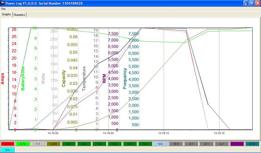
Simple PowerLog Graph
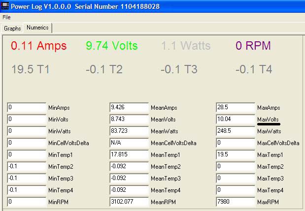
Simple PowerLog Table
Unfortunately, Simple PowerLog does not show the volts when the watts in were at 248.5, amps at 28.5 and RPM at 7980. The volts would have been 248.5 / 28.5 = 8.72v.
The other program, LogView has a graph view, somewhat similar to Simple PowerLog. Its Table view shows all of the logged data at a given interval, which can be useful.
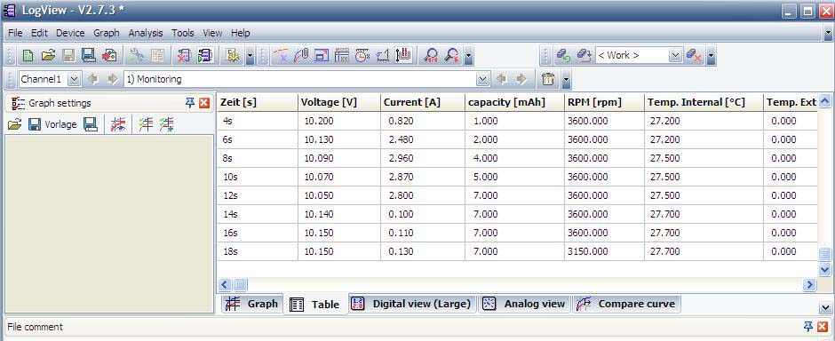
Data is a no load test
Tachometer is reading 2-blade inside ambient light
Unfortunately, the computer programs are the only way that the logged data can be viewed.
A good deal of time was spent using the manual, an Acrobat .pdf file, to learn how to navigate the various menus and sub-menus. The computer programs for use with the PowerLog 6 do not run on a Mac, but a Mac USB port was used to power the device during the familiarization.
The device may be powered by plugging a power source, USB cable or battery, into most of its inputs.
When the device is powered on, it quickly shows two startup screens. The first is the Logo Screen, which displays the serial number and firmware/software version. The Information (Inf.) screen displays quickly after the Logo Screen. The Inf. screen displays the type/chemistry of battery last selected and the logging status, file name or Logs Off.
The Three Input Keys
Three keys, on the face of the unit, are used to navigate through the various monitors and menus. There are two types of key pushes or presses. One is the tap. The key is pressed quickly. The other method is the hold. The key is held down for three (3) seconds or more or until the desired screen appears. There are a few instances where two keys are held down simultaneously and a few where a key is tapped twice. For the rest of this review, the word tap means to press a key quickly once and the word hold means to hold the button down for more than three seconds.
The TYPE key is at the top of the column of three keys. When it is held for more than 3 seconds in any of the 5 monitor screens, it pulls up the 'Select Type' battery and alarm menu.
The HOLD key is in the middle of the column of three keys. When held for more than 3 seconds in any of the 5 monitor screens it toggles the file logging on and off. It might better have been named the LOG or CAP (capture) key. Unfortunately, there is no way to actually hold information on any of the monitor screens.
The MENU key is at the bottom of the column of three keys. When it is held for more than 3 seconds in any of the 5 monitor screens, it pulls up the 'Main menu'.
The Five 'Monitor' screens
The device always starts up by displaying the last 'Monitor' screen viewed when the device was disconnected from the power source.
The Watt monitor (The power meter screen. The power meter has the ability to measure from 4.5 volts to 60 volts and -130 amps to +130 amps. Voltage measurements under 4.5 volts require an external power supply such as a 4-cell NiCad/NiMH receiver battery.)
The Cells monitor (Displays the individual cell voltages when a node/balance connector is connected to the device�s Multiple Voltage Input Port. The socket is designed for the JST-XH type connector. Progressive RC sells optional adapters for Thunder Power and Polyquest type node/balance connectors and wiring schemes.)
The Temperature monitor (displays the internal temperature of the device plus any optional added temperature probes. There is one additional temperature probe supplied with the device.)
The Tachometer monitor (displays the optical tachometer information. The unit reviewed here was set, by default at 03, meaning a 3-bladed prop. It was changed to 02 for 2-blade operation.)
The PWM monitor (displays pulse width modulation).
The five 'Monitor' screens are navigated by a tap of the bottom (MENU) button. Each tap of the bottom (MENU) button advances to the next 'Monitor screen' until all fives screens have been displayed and then repeats through the cycle.
The Cells monitor and Temperature monitor both have submenus that are accessed by holding down the top (TYPE) button and middle (HOLD) button at the same time for longer than 3 seconds. To return to the original 'Monitor screen', the bottom (MENU) button is held down for 3 seconds or longer.
The manual incorrectly notes how to get into the 'Select Type' menu and 'Main Menu'. Holding the top (TYPE) button enters the 'Select Type' menu and holding the bottom (MENU) button enters the 'Main Menu'.
The 'Select Type' screens are used to select the chemistry of the battery being used with the Multiple Voltage Input Port and the Alarm Settings. Three types of battery chemistries are preset and there are 5 User sets available. The three preset chemistries are LiPo (Li-Poly), Lilo (Lithium Ion) and LiFe (Lithium Iron Phosphate). There are Alarm Settings for; Cell Voltage, Pack Voltage, Time Over (pack voltage), Current (time over current), Power, Capacity, Temperature, RPM, Period and Pulse. The last two alarms relate to the PWM operation.
The 'Main Menu' includes Log Files, PWM Output, Motor KV meter, System..., and Calibration. Log Files has submenus to select whether logging is turned on or off and for the creation, selection, transmission, emptying and deleting of the log files. PWM Output has submenus relating to the pulse width modulation output and how it functions. The Motor KV meter has inputs that allow the Kv (RPM/v) to be determined. System... allows user changes to the system. The changes include; Temp. Units (C or F), Beep Tone, LCD Screen (brightness and contrast), Alarm Setting (not the adjustments, which are made in the 'Select Type' menu), Log Start (manual or auto with or without delay), Rec. Interval (sets the capture interval for logging), Start� (turns music on/off and controls the display on or off of the Logo Screen and Inf. Screen at startup), and Power Save (backlight on/off or sleep mode).
A Practical Example:
The following practical example uses a Scorpion S-3020-11 special wind motor. Previously, the drill press method had been used to determine the Kv of this motor. Its Kv was determined to be1225 using that method. The battery pack used for the example was a 3S "A123" 2300mAh pack (LiFe for this device) and the ESC was a Scorpion.
To prepare for the battery cell voltage check of the "A123" 2300mAh lithium iron phosphate battery, the battery chemistry was changed to LiFe.
How to change the battery chemistry
The top (TYPE) button is held until 'Select Type' menu appears.
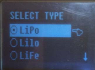
Note the dot in the circle next to LiPo. It is shows that LiPo is the selected battery chemistry.
The middle (HOLD) button is tapped (twice) to move down to LiFe. Tapping the top (TYPE) button or middle (HOLD) button acts as up and down arrow keys when a list appears in a menu and the bottom (MENU) button is tapped as the confirmation key.
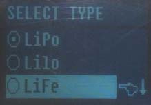
Next, the bottom (Menu) button is tapped to enter the LiFe screen.
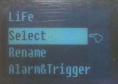
The Bottom (Menu) button is tapped to Select LiFe and to return to Select Type screen with LiFe selected.
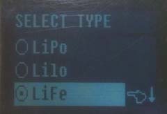
Now the dot in the circle shows that LiFe is the selected battery type.
For just checking the voltage of each cell, the battery type did not have to be changed from LiPo to LiFe, but it was a good exercise.
Motor Kv Test
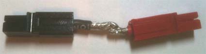
Several tasks were completed before the motor Kv (RPM/v) was tested. The supplied motor Kv measurements line for brushless motors uses 'alligator' clips. One 'alligator' clip is clipped to the negative lead between the battery and ESC and the other 'alligator' clip on any one lead between the ESC and motor. One set of bullet connectors, between the motor and ESC, was separated enough for the ESC to motor 'alligator' clip. A jumper connection was fabricated with Anderson Power Poles to fit in the negative lead between the battery and ESC for the other 'alligator' clip attachment point.
It appeared to be a good time to turn on the logging function and see what data was recorded during the Kv test.
Creating a Log file:
Hold the bottom (MENU) button to enter the 'Main Menu'.
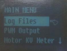
Tap the bottom (MENU) button to enter the Log Files.
The first time the Logs File is entered, there are no Log Files.
To create a Log File, hold the top (TYPE) button until the Create File screen appears.

A file name may be entered if desired. Tapping the bottom (MENU) button accepts and confirms the default name, LogFile1 in this case, and the program returns to the Log File screen. Only the newly created file is displayed.

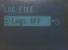
A tap of the middle (HOLD) button displays the new Log File with the Logs OFF option.

Holding down the bottom (MENU) button returns the program to the 'Main Menu' screen and holding down the bottom (MENU) button again returns the program to the 'Monitor' screens.
For this example, the Motor KV Meter was set up without returning to the 'Monitor' screens.
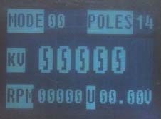
The S-3020-11 is a 14 magnet outrunner. Before the Motor KV Meter could be used, the number of Poles was set to 14.
From the 'Main Menu' tap the middle (HOLD) button twice to move the cursor down to the Motor KV Meter.
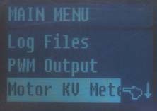
Once the Motor KV Meter is highlighted, tap the bottom (Menu) button and the KV Meter screen opens. It may or may not have the correct number of Poles (magnets) in the upper right corner.

In the example, POLES shows 08. To change the POLES to 14, hold the middle (HOLD) button until the Poles digits starts flashing. The top (TYPE) button is tapped to increase the POLES to 14. Once the correct number of poles is entered, tapping the bottom (Menu) button confirms the number.
The Motor KV Meter was ready to be used, and in this case, with logging turned on. Unfortunately, logging cannot be used when the Motor KV Meter is in use. Logging may only be initiated when one of the five monitors is in use. A lesson learned.
During the Kv (RPM/v) test, the Motor KV Meter screen was fluctuating between 1220 and 1230. That compared well to the test motor's measured Kv of 1225, using the drill press method.
Logging the Five Monitors:
The previously created Log File was emptied. The motor was set up for static testing with the battery connection through the power leads only. The battery node/balance connector was not connected. No external temperature sensor was used. The device was held so that the optical tachometer could take a reading of the spinning prop in ambient sunlight.
Logging may be initiated from any of the five 'Monitor' screens. For this test, the Tachometer monitor screen was active, but it didn't have to be.
Logging records ALL of the data from all five monitors, whether there is anything plugged into the device to gather the data or not. Since the node connector and external temperature sensor were not used, the data collected for them was null (0) and appeared in LogView as 0 (zero).
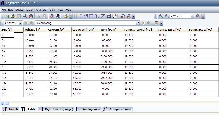
The table shows that full power was reached at the 12 second (s) mark. It also shows that at the 4 second point, the tachometer missed a count. The temperature measurement is still in Celsius.
The LogView table is very wide. The remainder of the table is shown below.
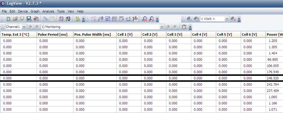
If the node/balance connector had been attached during the logging, there would be digits other than 0 (zero) in the columns Cell1 [V] through Cell 3 [V].
Using as a mAh input monitor
Many inexpensive chargers do not have a way of indicating how many mAh are returned to the battery during charging. The PowerLog 6S can be used to monitor the mAh returned to the battery.
The slightly used "A123" 2300mAh battery was 'zip charged' using a 12v marine/RV battery, a 9 ft. length of lamp cord (as a resistor), an AstroFlight Whattmeter, the PowerLog 6S and finally the 3S "A123" battery.
Before the 3S "A123" pack was attached, the AF Whattmeter showed 12.6v and the PowerLog 6S 12.7v when attached to the marine/RV deep cycle battery through the lamp cord. After the 3S "A123" pack was connected, the PowerLog 6S displayed very slightly lower amps through the whole charge compared to the AF Whattmeter. The PowerLog 6S displayed 134mAh returned to the pack and the AF Whattmeter 136mAh returned. When the 3S "A123" pack was disconnected, the PowerLog 6S displayed 12.47v while the AF Whattmeter displayed 12.3v.
There is no way to tell if either device is more 'accurate' than the other, but both are fine for the kind of testing they are designed for.
The Bottom Line:
At the field:
The PowerLog 6S performs all of the functions of a 'typical' power meter and an optical tachometer. That makes it a good value even before it does anything else!
It can be used to record some in-flight data, but setting the device up to capture RPM in-flight with the optical tachometer could prove somewhat awkward and impractical for the majority of airframes. It is too bad that the designer didn't link the electrical tachometer used to measure the Kv (RPM/v) to the Monitor functions so that it could be used in-flight.
It could provide valuable information on motor, ESC and battery temperatures during a flight with optional temperature sensors.
At home:
The PowerLog 6S combined with a Windows computer is a total static power testing elucidation. It is excellent for deriving the data that needs to be input into power system calculation programs similar to Drive Calculator.
Return to "What's In This Issue"
Re-gluing Motor Magnets
From Tom Cimato via email
The June issue of the Ampeer noted that Willie McMath had a problem with loose motor magnets. Tom Cimato, Mr. MaxCim, sent along this helpful information. KM
Regarding the loose Turnigy motor magnets, I suggest that you/they use Loctite 325 Superbonder Adhesive with 7387 activator. In outrunners, I'd apply the adhesive in the bell and the activator to the magnet's gluing surface.
Since most Neo magnets are nickel plated, I would scuff sand the gluing surface with a 180-220 grit paper and clean with acetone before applying the activator.
This adhesive has been qualified at temperatures in excess of 500F and retains magnets on rotors (inner rotors) in excess of 50,000rpm.
The epoxy that I would use would be 3M 2214B/A 2 part structural epoxy. Again, highly qualified at high temperatures.
That's my good deed for today :-)
Cheers,
Tom
And from Ron van Sommeren via email
Goedendag Ken,
Another method for gluing or re-gluing motor magnets is in the Torcman motor-assembly manual. It uses epoxy, cured at higher temperatures in the kitchen oven:
www.torcman.de/motoren/manuals/anl_eco_200e_scr.pdf
-> 3.1 Gluing the Rotor and the Magnets
-> 3.2 Filling the gaps between magnets
Vriendelijke groeten ;-)
Ron van Sommeren
Druten, Netherlands
Return to "What's In This Issue"
The Stinson Reliant SR-7 Flies!
From Gary Gullikson via email

Gary built a very nicely detailed Pat Tritle Reliant, which has been mentioned here before. The build thread can be found on RC Groups. KM
It was foggy and dark at Black Starr Canyon/OCMA/Bob Swenson field yesterday morning (June 21, 2011 KM). I taxied around and adjusted the tail wheel. Ted Broberg had his camera ready. After a confidence building flight with my Tritle C-140, it was time for the long awaited maiden.
I took off and immediately noticed that I had an anvil in the nose. OCMA buddy, Don, fed in lots of up trim but I landed it with lots of up elevator.
After adding some more stick-on lead to the stab the next flight was much better. The model behaves well with flaps down at low airspeed, much like my foamy PZ Reliant.
Today I went through the flight shots, cropped some of the fairly sharp ones and adjusted the brightness and contrast. I have attached some of the better shots for your entertainment.
The wingspan is just less than 58 inches. It weighs 52 ounces and power is a Scorpion SII-3014-1040, turning an APC 11x5.5E prop. The battery is a 3S 2200mAh 30C Li-poly using a 55-amp Scorpion ESC with a Park BEC. The radio system uses six Hitec HS-55 servos and a Hitec Optima 6 receiver.
I plan to modify the battery mounting for more rearward placement and do away with tail ballast. Anyways after a yearlong build, IT FLEW!!!!!

In his maiden flight notice, he stated that he also had the E-Flite version of the Reliant. This is what he had to say about it. KM
I read your article on the PZ T-28 conversion to A-123 power etc. with much interest.
I have really been enjoying flying the PNP version of the PZ Stinson SR-10 with the stock motor and 30 amp ESC with 700ma switching BEC while I finish up my Pat Tritle SR-7 short kit bash in Pepsi-Cola livery.
I'm using my Hitec Prism 7 with 2.4ghz module and Optima 6 receiver and 3S 2200mAh 25C Li-polys. It is a tight fit in the foamy Stinson SR-10. This "model" uses the same 2 digital and 2 standard PZ servos plus my HS-55 servo for flaps. I wondered about the "singing" servos but was told this was normal.
A few days ago, after doing my usual touch and goes, and gentle rolls, and loops, I flew it inverted for a while and tried to roll to right side up when it went into a "death spiral" and would not respond to controls.
After epoxying the fuselage back together. I went to my LHS and bought a new wing, motor mount, ring cowl and wings struts. The motor mount and prop are same as used on the newest T-28. Cost $50+ with club discount.
I will need to install servos for ailerons and the flap option in the bare wing. The thick molded plastic windshield is not a replaceable item. I would have to buy a new fuselage, etc to get the windshield. An E-zoner is sending me a salvaged windshield.
I will also need a decal set for the wing numerals not included with the replacement wing.
I plan to install a Park BEC and disable the 700mAh switching BEC for better insurance against brownout/reset/crash scenario.
I'm not sure that this was the cause of my crash. I did notice that the ailerons and other control surfaces have rather "stiff" hinging. The indented foam hinge lines backed with clear factory installed packing tape might have added up to excess servo amp draw more than the 700ma switching BEC can handle safely with 2 digital and 3 regular small servos.. I plan to use pinned hinges in the repaired model.
I don't like the 8mm prop adapter and need to use the T-28 prop that fits the adapter. This is a collet type that has no setscrew. I will say that the adapter and motor shaft survived the vertical crash into hard dirt without damage though the motor mount (same as for T-28) was broken.
I will plug the Park BEC into the "SPC" port on the Optima 6 receiver instead of into the throttle channel on the receiver per Hitec Optima instructions. This is intended to provide full power to the receiver alone per Hitec.
BTW, Hitec instruction sheets, in general, are too brief and lack clear explanations. You usually need to contact Hitec's "Alan T" or Mike Mayberry for advice.
Enjoy your thorough system testing which is somewhat beyond my capability.
Gary Gullikson,
Garden Grove, CA (E-Challenged on E-Zone)
Return to "What's In This Issue"
E-flite Rhapsody and PT-17 Stearman; A Comparison
By Ken Myers
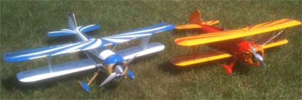
Paul Sockow, EFO member, completed a very successful maiden of his E-Flite Rhapsody sport bipe on Saturday, June 18. It flew well and by Sunday, he was greasing the landings. Not an easy thing to do with a biplane.

I had my Super Stearman conversion of the E-flite PT-17 at the field both days. I happened to have my Super Stearman up when Paul made is initial take off, so my first glimpses of his plane were in the air.
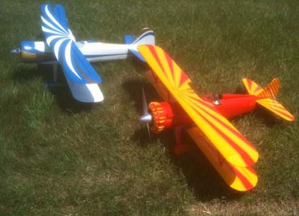
I have provided photos to show the similarities between the two biplanes.
Return to "What's In This Issue"
To Reach Ken Myers, you can land mail to the address at the top of the page. My E-mail
address is: kmyersefo@theampeer.org
EFO WEB site:
| 
