 |
Flying High With Electric Power!
The Ampeer ON-LINE!
Fly the Future - Fly Electric! |
Site Table of Contents
| President: | Vice-President: | Secretary/Treasurer: |
| Ken Myers | Richard Utkan | Rick Sawicki |
| 1911 Bradshaw Ct. | 240 Cabinet | 5089 Ledgewood Ct. W. |
| Commerce Twp., MI 48390 | Milford, MI 48381 | Commerce Twp., MI 48382 |
| (248) 669-8124 | (248) 685-1705 | 248.685.7056 |
 | ||
| Board of Directors: | Board of Directors: | Ampeer Editor |
| David Stacer | Jack Lemon | Ken Myers |
| 16575 Brookland Blvd. | 8908 Sandy Ridge Dr. | 1911 Bradshaw Ct. |
| Northville, MI 48167 | White Lake, MI 48386 | Walled Lake, MI 48390 |
| 248.924.2324 | 248.698.4683 | 248.669.8124 |
| Mailed Ampeer subscriptions are no longer available | ||
| The Next Meeting:
Date: December 3 Time: 7:30 p.m. Place: Ken Myers's house (see address above) | ||
|
New paper subscriptions to the Ampeer are no longer accepted. All subscriptions through 2010 will be honored. 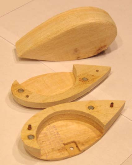
What does the photo above have to do with anything in this newsletter? Read on. :-) From Joe Hass Please check the Skymasters' Web site at www.skymasters.org for the latest information and flyer. Starting Tuesday, November 10, 2009
Lots of fun planned throughout the year. Many of the same sponsors have pledged to support us again. Joe Hass
Yes, you saw this info last month, but I wanted to be sure that everyone in the area knows about this. I also wanted to remind anyone visiting southeastern Michigan that they might want to include a visit to one of these flying sessions while they are here. KM THIS JUST IN! November 27, Friday, Skymasters is hosting a Thanksgiving Weekend Indoor Fly at the Ultimate Soccer Arena, 867 South Blvd, Pontiac, MI starting at 11:00 AM. The arena is located just west of Opdyke, on the north side of South Blvd. It is a 365 ft by 260 ft facility with ceilings from 45 to 75 ft. It is available for indoor flying from 11am to 3pm on Friday, November 27th!! There is ample room for concurrent flying of 3D, Heli, and Sport. It is a temperature controlled, well lit facility. There is a restaurant on site. It is just $15 for 4 hours of flying!
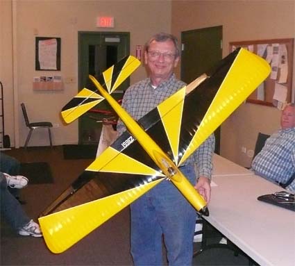
Control Line E-Power
Rick has been flying competition control line for many decades and has campaigned his electrically powered versions and conversions at local control line meets for several years now. Here is his in information on his latest conversion. The original airframe was completed in 1964! KM Even 45-year-old stunters can convert and fly well using electric power. It is a 1959 design originated in Detroit by Bob McDonald's father. This is the trike version 2 that was built in 1964 while I was in college. The only difference from #1 (the 1959 version) is a slight airfoil modification and pin striping!
Some Thoughts and a Plane
If you've read the Ampeer for a while you'll associate the name Rich Flinchbaugh with flying boats and float planes. In September I received a letter from Rich. At 79 he's slowly pulling back from the modeling end or our hobby. He noted that he was given a partially built PBY Catalina Flying Boat, which he intends to complete, but that will be his last building project. He is NOT out of the hobby by any means as he still has 25 flyable electric planes. He also included some information about his longtime modeling friend, Jeff Trenkler. KM 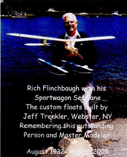 Jeff was a master modeler and well known in the Rochester, New York area. He was my best friend for well over 60 years. Jeff was really involved in floatplanes and flying boats. His final gift to me was the floats that are now on my Sportwagon. Before Jeff�s floats it had a mind of its own, and refused to fly with a larger set. It just loves the new 9 ounce set from Jeff. It now takes off in about 20 feet. Just before Jeff passed on August 16, I was able to tell him of the tremendous success with his floats. He was really pleased. He was a great guy! A while back Rich had sent the details and a photo of his Sportwagon with the big, clunky, original floats. KM 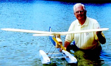 The photo was taken on August 5, 2008 at Scargo Beach on Scargo Lake in Dennis, MA. Rich is holding his Sportwagon floatplane. It was first powered by an 0.15 glow motor when it was a land plane. It has a new Mega RC 600/20/5 outrunner and it gets off the water fast. If flies for about 10 minutes. It makes a fine floatplane. A Miles Sparrowhawk
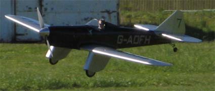
Dear Ken, It may be down to age but I've always been a sucker for Miles and Percival aircraft, as these aircraft often seem to be the very best of classic style. Seagull, the Vietnamese company, has produced three versions of the Miles Sparrowhawk and a Percival Mew Gull, all to very high standards. I decided to purchase one of the 63" span Sparrowhawk (the smallest) as a trial. I can't say that the colour scheme in yellow, silver, turquoise with touches of red was likely to look like one of the five real Sparrowhawks but, as I said, it was well made and came with a very good electric conversion pack. As this was designed as a sport scale model I decided that rather than try to produce mine to follow one specific aircraft I would just attempt to emulate the style of Miles so that it would be immediately (I hoped) recognisable.
Regards,
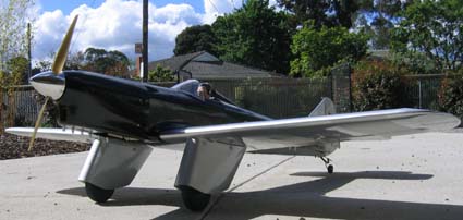
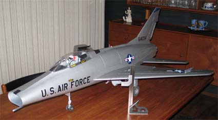
Like it? LOVE IT! It's my kind of plane for sure. It is always good to see what is happening from "down under." KM 1/10-Scale F-100D
Hi Ken! Many thanks for your continuing fine support for electric-powered model builders!! The November issue of "Ampeer" is most welcome and informative!! Attached is a shot of my 1/10th F-100D, and a short description. I'm still doing some 'adjusting' (OK, correcting a few mistakes); weather has gone south, and the model needs a hard surface runway, so probably won't try any flying until next spring. F-100D Model Description As of: 18 October 2009
Main Characteristics
Model features:
Model Description, continued
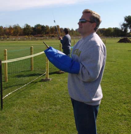
Jim Young's Transmitter Bag/Mitt
Several of you noticed Jim's transmitter bag in the November Ampeer. Jim sent the following information to share with you. KM I found the pattern here: www.blueangels.rchomepage.com/transmitter_glove.htm
Two Useful Indoor Tools
Plenny took a couple of photos of these useful tools and passed along the following information. KM A couple of kids in Michigan have come up with a way to help pay their way to a big indoor contest. They are selling a balsa stripper and a neat glue dispenser. Harry Geyer, who was Beacon Electronics, brought the Good Brothers radio to market in the mid '40's. Later he made a glue dispenser very much like the one the Tyson boys are selling. It was a winner for those who wanted to keep their weights down and their times up. 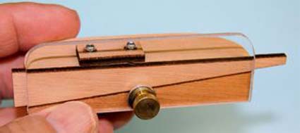 The small block held down by two screws holds the blade. The ramp has no markings. After cutting test strips you may wish to mark its position for different sizes. It needs a pin or screw to the right of the thumb screw to keep the plastic fence from rotating. 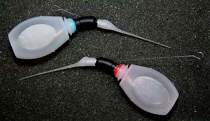 This is one great tool. Thin your Duco, Sigment or Ambroid (you do know those glues don't you? KM) and place in bottle. To dispense "large" amounts pull the wire mandrel back and squeeze. For a very small drop pull the wire back, force some glue into the capillary tube and now push the wire out with a micro drop of glue on its tip. When done pull the wire back even with the end of the capillary tube. The post paid prices are $20.00 for the stripper and $10.00 for the glue dispenser. Order from:
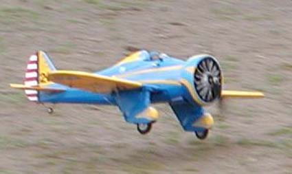
Power for Big Radial Engine Models
I enjoyed your extensive advice and recommendations to "Mark" about his semi-scale Gee Bee project. I don't have your technical expertise in choosing motors, battery packs and props for "golden age" radial engine/cowl ring models. I installed three progressively larger motor/battery/prop diameter/pitch in my own-design 40" w/s P-26 Peashooter and have been doing the same on a hand-me-down GWS foam PT-17. I have found that I need to find a "sweetest spot" of thrust and airspeed versus battery pack/overall model weight, given that everything is mounted as far forward as possible to minimize need for nose ballast. Also, the location of main gear axles is critical to avoiding nose-over tendencies but not promoting ground loop tendencies. Biplanes are a whole "nuther" story.
The E-flite Stearman PT-17 15e ARF:
In last month's Ampeer I mentioned that I was interested in purchasing an E-flite Stearman PT-17 15e ARF, and I had speculated on how I would power it. After a trip to my dentist in Brighton, for a pre-oral surgery consultation, I stopped by Rider's in Ypsilanti and purchased the kit.
The first issue for me is the recommended center of gravity/fore and aft balance point (CG for short). The manual, on page 25, states; "The recommended balance point for the PT-17 is 3-1/4 to 3-3/4 inches (82mm to 95mm) behind the leading edge of the upper wing." and "Due to the short nose moment of the Stearman PT-17, between 2 to 4 ounces of nose weight will be required." On page 3, in the section "Required Tools and Adhesives", Stick-on lead weight is listed.
Aug 07, 2009, 1Radioflyer (Jay) - Was tail heavy. CG was set to 3 3/4". Aug 09, 2009, ATIS (Bryan) - Was tail heavy as well. Required all the available down trim to keep from looking like a homesick angel. Went nose high fast. CG set at 3-3/4" from LE. Needs to be closer to 3-1/2". Aug 15, 2009, ducatirdr First flight near disaster. Ounce of weight in cowl. Lifted off, climbed like a 3D. Fed down, more down, almost out of travel. Managed to turn the plane into the really tall grasses and flowers. Settled softly. Loaded 4 oz. inside of the cowl before the next flight. Took off, still climbed hard. Used all trim to get it near level flight, still needed more down. Aug 18, 2009, AZThud 3 ounces of nose weight. Balance just back of 3-1/2". Initial climb out very scale like. As model accelerated, angle of climb increased. Couple of clicks of down elevator. Looked up, Stearman at full throttle climbing into hammerhead. Aug 19, 2009, Staggerflyer Opened throttle about 3/4. Experienced, long time club test pilot, never open full throttle on first take off. Tail came right up, touch of right rudder; touch of up elevator, smooth lift off. Needed 2-3 clicks down and 1 click of right aileron. CG point was right at 3.5" Never over 3/4 throttle. Aug 22, 2009, Navy Fly Guy Added 6 oz. of lead and epoxy to cowling along with 6 clicks of down trim before the takeoff run. CG at 3-1/2 inches. Added another ounce of lead, re-trimmed aircraft. Aug 24, 2009, Greyrush Popped nose-up right away. Elevator maybe a good 2-3 degrees down. Aug 25, 2009, AtomHeartMother Balanced at 3.5 inches. Initially climbed pretty steep. Settled at 2 clicks of down trim and one click of aileron trim. On ground just a hint of visible down trim in the elevator. Aug 25, 2009, dgliderguy A bit too tail-heavy. CG right at 3.5", felt like the very backend of the envelope. (Remember his remark from above? KM)
Sep 05, 2009, turbonut Airland Hobbies (Scott) Needed 3 clicks left trim, 2 down for level flight. Try taking out some of the 6 oz. of lead in the nose and look for the aft CG limit. Sep 15, 2009, blk822 Had the straight up on take off problem and crashed it. Believe CG at 3-1/4" with a 4 oz. weight in the cowl. On take off, jumped straight up and pitched over to the left. Only broke cowl and motor box. Sep 15, 2009, stuart warne Added washers to raise the top wing LE and added 4 oz. of lead to the nose. Sep 19, 2009, Staggerflyer Forgot to add a few clicks down trim. Leaped off and went straight up. About 4 clicks of down trim to get flying straight and level. 4 oz. of lead in nose, balanced 3-1/2 inches from leading edge. Sep 20, 2009, Sticky Mickey Two Stearmans maidened today, both survived. Both required a heap of nose weight. Sep 20, 2009, CyberJay (Jay) CG is almost exactly at 3.5". Still tail heavy. Exciting maiden. Got it down in one piece. Adding a couple of ounces to get the CG up to 3.25" or maybe 3". First "bad maiden" ever. Extremely lucky to get it down. Added SIX ounces to the nose and re-maidened. Oct 18, 2009, krazyman (Terry) Maiden was a complete disaster. It left the ground and went straight up - came straight down. CG set at 3-1/2 inches, flew as if it was very tail heavy. Oct 21, 2009, PM k4to.dave Violent pitch up after liftoff, even on half throttle. Couldn't get enough down trim to level it. Able to get it back on the ground - no damage. Next step, another washer's worth of down thrust. Control surfaces neutral, a shade of down for the elevator is in order. Oct 28, 2009, lowbubba (Randy) Had 6.5 oz. of lead in the nose. Flew GREAT. Put a lot of down trim in the plane. CG at 3-1/8 inches. Put 2 small washers under front cabane struts. Nov 1, 2009, Navman - Two 1mm washers in the top motor mount to angle the motor down, ton of weight in the cowl to get the CG right. Landings are a little hot but manageable. Did not have to add any down trim. Nov 02, 2009, Kauz (Frank) Modifications - replaced heavy pushrods, installed 2mm Bowden cables, lighter servos all four positions, shifted rudder and elevator servos a little more forward, didn't use the tail wheel assembly, just wire skid. Added 70g (2.5 oz.) of lead in the cowl for a proper CG at 3-1/2". Nov 03, 2009, Chinookmark - 3 ounces of BBs epoxied in lower 4 cylinders, balance right at 3.5", 5/32 carbon tube pushrods, one washer down thrust, one washer positive incidence on the upper wing, added about 1/16" down trim with the pushrod before it flew, flies great. Nov 6, 2009, mikeronie (Mike) - 5-1/2 oz. of nose weight in the dummy cylinders. Balanced at 3-1/4". Took off in about 30 feet, climb out was not too steep. Nov 7, 2009, philipm785 - 3 oz. lead in the nose, balances around 3.25". Ready for head skyward but takeoff was actually very scale. Needed a few clicks down trim to fly level at 3/4 throttle. One interesting thing to note is that there are at least four posters early in the thread that have some affiliation with Horizon Hobby/E-flite. They talk about and promote the plane. None of them have responded about the flight characteristics since the maidens started.
DECALAGE-WORTHWHILE OR A RIGGING NUISANCE? Decalage is the difference between a bipe's two wings' angles of incidence-the angle at which the wings are placed in relation to the fuselage. Positive decalage gives the upper wing more incidence-negative decalage-the lower wing more incidence. (This is what the out of the box Stearman has. KM)
In the RC Groups' thread, some folks noted that they are changing the negative decalage to positive decalage to try and dampen the abrupt climb out. According to Carl Risteen, the negative decalage should be helping this model in that regard, and it should have no effect on the CG. No one in the thread has reported any kind of "wicked" stall, once they managed to get the plane flying successfully with the designed-in negative decalage, so the efforts to change the decalage are probably not all that useful, but they don't seem to be hurting anything. I spoke with Keith about this matter, and he concurs. (The next section notes how his 1/6-scale Super Stearman is set up and you'll see why. KM) Personally, I am going to leave the decalage alone. The third issue is the incidence of the horizontal stabilizer/elevator. The reported successful maidens seem to be a combination of down elevator trim and placing the CG between 3-1/8" and 3.5" from the upper wing's leading edge. Most of the posters reported having successful flights with a CG of about 3.25" (82.5mm) from the leading edge of the top wing. The down elevator indicates that the horizontal stabilizer/elevator assembly needs to have a bit more positive incidence. Many times a slightly negative horizontal stabilizer/elevator assembly incidence is used on planes, compared to the wing incidence and thrust line. The stabilizer's relative negative incidence is used to balance the natural forward rotation of the wing(s) as it creates lift. In this case though, the top wing's downwash is having an affect on the horizontal stabilizer/elevator assembly and its relative angle. Since the stock model cannot easily have its horizontal stabilizer/elevator assembly incidence changed, the down elevator trim has to be "lived with." Using my Robart incidence meter and paper and a ruler for measuring for down and right thrust, I found the stock setup to be:
For well over 20 years, Keith Shaw has been flying a 1/6-scale, 1200 sq.in. model of a 450hp Super Stearman. It is modeled after Bill Barber's "Black Baron". These are the incidences that he used on his great flying model.
The fourth issue for me is the advertised wing area. Printed on the cover of the manual, and noted on the Horizon Hobby Web site, the wing area is given as 608 sq.in. Over the years I have found that many suppliers give an incorrect wing area. When I drew a CAD version of the plane to help me with the modifications I wish to do, I calculated the wing area as 553.5 sq.in. I included the 12.6 sq.in. of the bottom wing what would be "inside" the fuselage, if it existed, as it is a "standard practice" to do so on our models. Just to double check, I re-measured everything very, very carefully, drew the wing tips and physically cut up the paper wing tips and placed the "pieces" into 1-inch squares. Using this method I calculated the wing area as 557.4 sq.in. I believe that it would be fair to note the wing area as 555 sq.in., NOT 608 sq.in.
Don't be afraid of getting the plane too heavy by balancing it at 3-1/4" from the leading edge of the top wing for the first flight. When you set up the elevator to be "neutral" on the transmitter, the elevator on the plane should have some apparent down trim. Put a washer under each of the top motor mount lugs to add more down thrust. You shouldn't need to change the decalage. Do not apply full power for take off. |
To Reach Ken Myers, you can land mail to the address at the top of the page. My E-mail
address is:
KMyersEFO@theampeer.org
EFO WEBsite