|
Flying High With Electric Power!
The Ampeer ON-LINE!
Fly the Future - Fly Electric! |
|---|
Site Table of Contents
| President: | Vice-President: | Secretary-Treasurer: |
| Ken Myers | Richard Utkan | Rick Sawicki |
| 1911 Bradshaw Ct. | 240 Cabinet | 5089 Ledgewood Ct. W. |
| Commerce Twp., MI 48390 | Milford, MI 48381 | Commerce Twp., MI 48382 |
| (248) 669-8124 | (248) 685-1705 | (2480 685-7056 |
 | ||
| Board of Directors: | Board of Directors: | Ampeer Editor |
| David Stacer | Arthur Deane | Ken Myers |
| 16575 Brooklane Blvd. | 21690 Bedford Dr. | 1911 Bradshaw Ct. |
| Northville, MI 48168 | Northville, MI 48167 | Commerce Twp., MI 48390 |
| (248) 924-2324 | (248) 348-2058 | (248) 669-8124 |
| The Next Meeting: Date: Thursday, December 12 Time: 7:30 p.m.
Place: Ken Myers' house, Commerce Twp., MI | ||
| Servos, I Don't Know Jack!, Ken Myers discusses what he knows, has learned and doesn't know about servos. | Ah, Spring, Can It Be Far Away? Some photos from the April 2013 EFO Flying Meeting. |
| The 3 Watts In Per Gram of Motor Weight Rule of Thumb Ken Myers discusses this 'rule of thumb'. | |
By Ken Myers September 2013 Product Use - FAQ From Futaba: What servo do I need for my (insert application here)? Please consult the manufacturer of your model. They have extensively tested the model and know how much torque, speed and what size servos are most appropriate for that application. Once they've given you those specifics, please visit our servo chart to select a servo which fits your model's specific needs and your budget. While assembling my Maxford USA Antonov An-2, I found this statement on the Specifications on page 4 of the manual regarding the servos to use, "Servos - 6 mini servos for electric power / 7 mini servos for glow power". The word mini was also used on page 3 in the section "Items you must supply". At the Maxford USA page, they showed "Hitec HS55 servo x 6 (+ $66.00)" available as part of the Combo with ARF. I almost exclusively use Hitec servos in all of my projects. The mini servo, that I know of from Hitec, is the HS-225; HS-225BB Mighty Mini Servo. Some of the Specifications from the Hitec RCD web site for the HS-225:
"The servo that was in the Maxford USA Combo is actually called the "HS-55 Economy Feather Servo" by Hitec. Some of the Specifications from the Hitec RCD Web site for the HS-55:
For the purpose of the article, the servos discussed are non-specialized types, excluding such specialized servos as retract, thin aileron, etc., from the suppliers' smallest through what they call standard. Hitec combines Micro & Mini servos together on their Web site and has another category called Sport. The Micro & Mini servos include the names; Nano, Feather, Micro, and Mini. Sport includes various 'standard' servos. Other suppliers' naming conventions:
A servo spreadsheet workbook was created using some servo data from some of the suppliers' data. The spreadsheet illustrates that the most important "defining" measurement is not the servo weight or even the torque. The case length, without the mounting tabs, is a much better way to 'define' a servo group. That is not to say that torque and weight are not important, but for creating groups, the case length, without the mounting tabs, appears to be a better way to go. Almost all of the suppliers use Standard to define a servo with a case, not including the mounting tabs, between 38mm and 41mm long with weights ranging between 35g and 60g and torque ratings between 33 oz-in and 180 oz-in at 4.8V. I thought that after all of these years in the hobby, I knew what a standard servo was. I was wrong! The Almost Ready to Fly (ARF) model airplane is dominating the market today. Many of the ARF type models have servo trays and aileron mountings preinstalled, or spaced in the construction, for a specific servo length. The Maxford USA An-2 used a spacing of about 24mm. The existing servo slot 'length' can often be 'changed' by the experienced modeler, but the beginner might not have the tools, materials or knowledge of how to do so safely. The beginner must rely on the supplier's recommendation, per Futaba. The spreadsheet demonstrates that there are two different length cases for what various suppliers call mini servos. One type of mini servo has a case length of 35mm to 36mm and the other a case length of 31mm to 33mm. If the ARF supplier had the Mini servo cutout produced for a 36mm case length, like the Tactic TSX25 High-Speed Digital Mini, and the purchaser bought a 31mm case length Futaba S3016 Mini BB Metal Gear Servo, there might not be enough 'meat' in the tray for the servo screws of the Futaba to 'bight' into. The cutout for the servo tray would probably be about 38mm for the Tactic. The 7mm difference between the 31mm case length and 38mm cutout is over 1/4" different. The word mini can just mean small, but as defined by the servo suppliers it seems to mean servos between 31mm and 36mm. What the suppliers term "Mini" servos will not fit into the servo cutouts in the An-2 without modification to the servo tray and aileron/flap mounts. Micro servo case length is between 28mm and 30mm. Micro servos would also require 'work' to the servo mounting to be fitted into the An-2. Sub-micro servo case length is between 22mm and 23.5mm. The preexisting mounts in the An-2 are for Sub-micro servos. Sub-micro servos weigh between 6g and 12.5g and are rated between 8 oz-in and 41.7 oz-in of torque at 4.8v. The land version of the An-2 is a 6 lb. plane, and the float version is an 8 lb. plane. The recommended Hitec HS-55 servo is a sub-micro servo with 15 oz-in of torque at 4.8v. From my past experience with 6 lb. planes, I had anticipated using Hitec HS-225s on the elevator and rudder, HS-85s on the ailerons and maybe some HS-82s on the flaps. Greg Gimlick, electric flight columnist for Model Aviation, was working on a Maxford An-2 for a review at the same time I was assembling mine. We exchanged a great number of emails during my assembly of the An-2. He suggested that I might want to try some Heads Up RC Hobby Shop Power Up 12g Digital Metal Gear Sub-Micro Servos. Some of the Specifications from the Web page:
Greg noted that even though these are digital servos, they do not seem to be power hungry. He also noted he'd used them in several planes and they were working well for him with only one failure so far. I missed the word digital in the name and ordered the Power Up 12g Metal Gear Sub-Micro Servos. The specification for this analog servo showed exactly the same 'numbers' given for the digital servo. It seems to me that the Chinese just seem to make up numbers and pass them along to anyone who will purchase and distribute their product. After the servo ordering error on my part, I decided that I needed more information about digital and analog servos. I found more information at rchelicopterfun.com/rc-servos.html. The article is called "UNDERSTANDING RC SERVOS DIGITAL, ANALOG, CORELESS, BRUSHLESS", but the author is not credited. The information seemed reliable to me. I decided to put the analog servos in the An-2. During one of the times that the plane was taken to the field, I remarked to Arthur Deane, the Midwest RC Society president, that I didn't believe that Hitec HS-55 servos would work adequately in this 6 lb. plane. My personal experience had led me to believe otherwise. Arthur took some measurements and asked about the control throws in degrees for the elevator, rudder and ailerons. After he "ran" the numbers he got back to me and shared his results. They indicated that HS-55 servos could have worked, providing that the pushrods were free moving and that there was no binding. I still didn't believe that a 6 lb. plane, with a calculated 58 mph pitch speed, would be okay using Hitec HS-55 15 oz-in torque servos. For many years there was an online Servo Torque Calculator created by Chuck Gadd available on many RC related Web sites. It disappeared for awhile, but it has returned. There is another Servo Torque Calculator created by Craig Tenney. It is in an Excel 5.0 worksheet format. It is still available from the Aircraft Proving Grounds Web site. Please read and understand all of the caveats about this type of calculation. Two separate aileron servos are used in the An-2. Therefore, the elevator has the most surface control area. It is used for the example. Maxford notes that the elevator travel should be 3/4" up and down from the center or 15 degrees. Actually, 3/4" up on a 2-3/8" wide elevator is 17.5-deg. The elevator is, on average, 2-3/8"/6.0325cm wide and about 20"/50.8cm long. I noted the length in centimeters, since the Craig Tenney calculator uses width and length in cm but yields torque in oz-in. The actual flight speed is unknown, but the calculated pitch speed is 58 mph. The Excel workbook requires knowing the "Maximum deflection of servo arm from center (degrees)". I thought that it was 60-deg, as all of the servo speeds I saw were for 60-deg. Then, while looking at the HS-55 data on the Servo City Web site, I found this: "Operating Angle: 40� one side pulse traveling 400usec". I pulled a Power Up aileron servo out of the An-2 and measured the angle from centered to where the transmitter signal stops it in one direction. It was 45-deg. I also measured the length of the servo arm from the center of the servo screw to the center of the furthest hole. It was 15mm or 0.590551 inches or about 19/32". 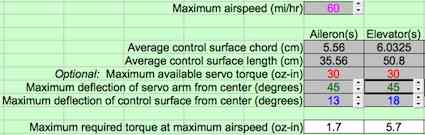 The results of the Tenney calculator demonstrate that with an airspeed of 60 mph and servo throw of 45 degrees, 5.7 oz-in of torque would be required for the elevator under perfect conditions. But... To paraphrase a statement on the Gadd calculator; Reducing the servo deflection from the default degrees, using "Dual rates" to set the proper control surface deflection greatly, increases the load on the servo. To get the recommended throw of 3/4" up and down on the elevator of the An-2, dual rates were used. That reduced the full throw of 45-deg to 55% of 45-deg or 24.75-deg.  Adjusting the servo throw in the Tenney calculator using the dual rate function of the transmitter for less throw showed the 12.3 oz-in result for the elevator as shown above. There are other considerations to take into account as well. The airspeed could exceed 60 mph, but it probably won't by much for this particular plane because of the way it is flown or its mission. There is no friction accounted for in the pushrod and control horn system or the hinges in the calculated torque requirement. Arthur Deane suggested that a 15% increase in torque is required to allow for friction, particularly with jacketed push-pull rods. The number is based on his many years as an engineer. 15% more required torque would be 12.3 * 1.1764706 (the inverse of .85 or 85%) = 14.47 oz-in. That is the prediction, with Arthur's friction increase, for the Power Up servos installed in the An-2, not HS-55 servos. How much a Hitec's HS-55 40-deg throw would need to be reduced to achieve a 3/4" throw is hard to say. Other considerations The smaller a servo becomes, the smaller the gear diameter and thickness become. Many servos, even some 'so called' metal geared servos, use a 'nylon' or 'plastic' or 'resin' primary gear, as well as other 'plastic' gears. The smaller gears, especially if produced with inferior Chinese 'plastic', are prone to gear teeth breakage just from everyday handling and the loads produced by a tailwheel or nose gear. 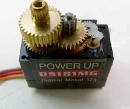
Greg Gimlick photo Notice that all of the gears in the photo of the metal gear servo are not metal. The 'nylon' or 'plastic' or 'resin' primary gear is stripped. Planes that regularly 'power dive' for one reason or another could reach speeds well in excess of the pitch speed quite often. Somehow, that must be taken into the calculation. With all of the variables involved, it is no wonder that we cannot accurately 'size' servos and that we tend to error on the side of caution, which we should! My Takeaway: There does not appear to be a good empirical way to select the correct servo. Torque calculation programs and spreadsheets give only a rough idea of the torque required under ideal and limited conditions. Today, many, if not most, servo suppliers use the length given in the dimensional data as the case length without the mounting tabs. That was not always the case, and some still include the mounting tabs in the length. On Futaba's Discontinued Servos page the length includes the mounting tabs, but for their current servos they note the case length without the mounting tabs. A servo that is set up mechanically to provide the 'correct/desired' amount of throw requires less torque to do so than one that uses dual rates to reduce the throw to the 'correct/desired' amount. The data for identical analog and digital servos from the same supplier that claim the same torque and speed should be considered suspect. As perviously noted, the Power Up servos do that. Hitec doesn't. Compare the data for the analog HS-85MG Mighty Micro to the data for the digital version, the HS-5085MG.
Some suppliers claim metal gears for servos that are a combination of metal and 'plastic'. Further research reminded me that I should not have been surprised by some of the 'smaller' servo recommendations of today. In the spring or summer of 1984 I built a Spickler Quickee 500 and powered it with a direct drive Astro Flight Cobalt 40 using 18 NiCad cells. While my flying buddy, Keith Shaw, had recommended standard size servos for '40-size' aircraft, I wanted to save some weight on what was going to be a pretty heavy plane and chose to use three Futaba S-33 servos. I had 'heard' that the glow Quickie racers were using them. There specifications were; 28.2 x 13 x 29 mm (measured), 27.8 oz-in of torque at 4.8v and they weighed 17g. I never had a servo problem in this relatively heavy and fast airframe. 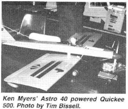 The photo of the plane is from Jim Zarembski's Silent Power column in the May 1985 issue of Radio Control Modeler. The photo was taken by Tim Bissell at an electric symposium in October of 1984. Peter Waters, Keith Shaw, Art Arro and I were the presenters to the Plymouth Flying Pilgrims. When they became available, I switched to Hitec HS-80 servos. The specifications for the HS-80 was 28 x 13.7 x 28.2 mm, 31 oz-in of torque at 4.8v and it weighed 17.5g. Both the Hitec HS-80 and Futaba S-33/S-133 were micro servos by today's standards. The 4.25 lb. Super Stearman I created three years ago uses Hitec HS-80 servos for the elevator and rudder and Hitec HS-65s for the ailerons. Installing Sub-micro servos in the 6 lb. An-2 has moved me 'down' another notch in servo power. All I can say is, "We�ll see how these hold up over time." I am in no way suggesting the use of 'small' or lower torque servos in large aircraft! Follow the airframe supplier's recommendation, unless it seems unrealistic because of your personal experience. Let's all be very careful with the servos that we choose to use. Safety first! I'd love to hear about more experiences with servos and their sizing! Here are a few photos from the April 2013 EFO flying meeting. Hopefully they remind us of what we can do once we get through winter here in Michigan! 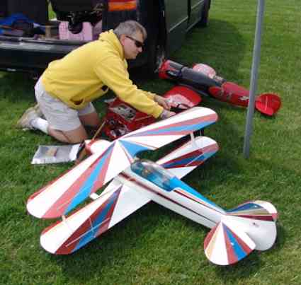 Jim Young prepares his Super Skybolt.  On the flight line. Waiting for the leaves to appear on the trees.  Chowing down. One of the things we do best! By Ken Myers On September 16, 2013, Lucien Miller made a very interesting post in the "Scorpion Motors: Questions and Answers...." thread on RC Groups regarding the widely accepted, by some, 3 watts in per gram of motor weight rule of thumb for maximum watts in (W-in). The link to the post on RC Groups. Here is what Lucien posted: The 3 watts per gram rule (of thumb KM) holds well for cheaper, less efficient motors, that have a throughput efficiency around 75% or so. However, it says nothing for the voltage level that the motor is being run at. You can have a motor that is fine with 6 watts (W-in KM) per gram (of motor weight KM) running on 8 Li-Po cells, but will only handle 3 watts per gram on 4 Li-Po cells. The amount of power that can be run through a motor also varies dramatically with the efficiency of a motor. The key thing to look at is the inefficiency of a motor to see how well it will handle power. (bold by KM) If you have a motor that is 75% efficient versus a motor that is 87.5% efficient, you might say that one motor is 12.5% more efficient than the other. The truth is that one motor is 100% more efficient than the other. How so you may ask? (bold by KM) If you look at the two motors, one is 25% inefficient, while the other is only 12.5% inefficient. If you run 1000 watts of input power into the first motor, you will get out 750 watts of work energy and 250 watts of heat energy. In the second motor you will get out 875 watts of work energy and only lose 125 watts to heat energy. From a standpoint of energy loss, the 87.5% efficient motor can handle TWICE the input power of the 75% efficient motor and end up with the same amount of waste heat. The main ways to increase the efficiency in motors is through the use of good materials, good motor design, and good copper fill in the stator. Most cheap motors uses generic steel laminations that are primarily designed for use in transformers. These materials retain high levels of residual magnetism during each switching cycle, and this causes additional heating in the core of the motor. Scorpion motors use special steel that is specifically designed for use in brushless motors, and has higher efficiency, so it has less internal losses. Scorpion also uses extremely strong magnets in their motors, and that also increases the efficiency of the motor. All Scorpion motors are hand wound with as much copper as can possibly be fit into the stator slots, and again, this helps to increase the efficiency by lowering the internal resistance of the motors. I have run a lot of motors on the test bench, and measure the temperatures (bold by KM) of them during the tests to see how they perform. In our own two brands of motors that we distribute, Cobra and Scorpion, there are similar size motors that have been tested on the bench. I will compare a Cobra 4120-18 motor, which has a Kv value of 540, with one of the new Scorpion SII-4020-540 motors, which also has a Kv value of 540. The Cobra motor has a 41mm x 20mm stator and the Scorpion motor has a 40mm x 20mm stator so both are very close in size. The Cobra 4120 motor weighs 10.23 ounces or 290 grams, while the Scorpion 4020 motor weighs 288 grams or 10.16 ounces, so again, they are nearly identical. The Cobra motor has a maximum current rating of 54 amps, and on 6 cells (22.2 volts) you have a maximum power rating of 1199 watts (W-in KM). The Scorpion Motor is rated for 85 amps, so on the same 6-cell battery, you can get 1887 watts of power (W-in KM). For the Cobra motor, if you take 1199 watts and divide that by 290 grams you get 4.13 watts per gram (of motor weight KM). With the Scorpion motor, if you take 1887 and divide that by 288 grams, you get 6.55 watts per gram. Both of these are significantly higher than the standard 3 watts per gram that everyone tends to use. If you take this to an extreme and look at some of the Scorpion helicopter motors that run on 12 Li-Po cells, you will see some astonishing efficiency numbers. For example, the HKIII-4035-560 motor can take 100 amps of continuous current. Running on 12 Li-Po cells (44.4 volts under load) you get a maximum power of 4400 watts (W-in KM). This motor weighs 460 grams, so if you do the math 4400/460 gives you a power handling of 9.56 watts per gram, which is over 3 times higher than the "Normal 3 watts per gram". In the October 2013 Ampeer I noted a formula that I now use to ascertain the maximum watts in (W-in) for a given outrunner motor, based on its weight. No formula for a rule of thumb, that I know of, allows for a 'more efficient motor' compared to a 'less efficient motor' of the same weight, so it can only be used as a very general rule of thumb, but one that I feel that is better than just always using 3 watts in per gram of motor weight. My formula for maximum W-in:
For a 290g motor that would be 290^0.25*290 = 1197 W-in.
That works out very well for the Cobra, but not so well for the Scorpion discussed by Lucien.
It also does not work well when there are several different winds of the same motor available.
The Cobra C-4120 series has 5 winds available that provide Kv numbers of; 430, 540, 610, 710 and 810. The higher the Kv the fewer the number of winds. The fewer the winds, the larger the diameter the wire is, and the lower the resistance is and the higher the efficiency is.
Actually, trying to find the highest acceptable Pin is not very realistic for most folks.
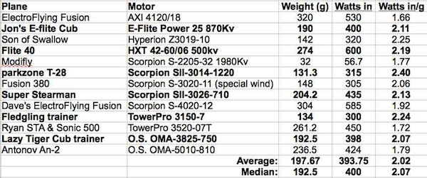
The table shows W-in per gram of motor weight in actual use for several of mine and my friends' planes.
It appears that we are possibly under utilizing our motors, but all of these planes are flying 'well' by OUR definitions.
The motors selected are used for balancing the aircraft rather than adding dead weight to the nose. They are operating at quite efficient levels, with "reasonable" amp draws.
Lucien Miller recommends that outrunner motors are used with props that load the motor to between 50% and 80% of the possible maximum power. This is based on the maximum continuous amp draw and number of cells being used.
Note: That is NOT the 50% efficiency point! The 50% efficiency point for the aforementioned Cobra motor using 14.8V is at about 3996 RPM (approximately 1/2 the no load RPM). At that point the amp draw is well over 100 amps with about 1/2 the input energy being turned into heat.
There are many different ways to use any given motor. No one way is necessarily better than another.
Over the years I've collected and collated a lot of information about prop driven model aircraft and their power systems. Here is a spreadsheet containing that data.
I am mainly interested in sport and sport scale type planes. On the spreadsheet workbook, I show that these types of planes fall largely into two levels that are based on their Wing Cube Loading (WCL). The levels are sport/trainer and advanced sport and both levels contain stand-off scale type planes.
One way that I select a motor involves three elements that define its type or WCL level. Two of the elements are derived from the aircraft's ready-to-fly (RTF) weight.
Level 4 Electric Power Elements
Level 5 Electric Power Elements
The Prop Factor (PF) is based on the disk loading of the propeller. The numbers indicate I use a smaller prop diameter than the average and median logged aircraft of this type.
What? Scratch Head Here
The spreadsheet that I have for my past and current planes shows my ElectroFlying Fusion sport plane with a 5S 4000mAh LiPo weighs 73.9 oz. and has a WCL of 9.42. That places it in the upper area of the WCL Level 4.
The wing area can be derived from the weight and WCL.
73.9 oz. / 9.42 (WCL) = 7.845 ^ 0.6666667 (the inverse of 1.5 used for cubing) = 3.948 sq.ft. * 144 (sq.in. per sq.ft.) = 568.5 sq.in.
The prop diameter is derived using the Prop Factor (PF). The prop factor for the ElectroFlying Fusion is 1.53 and is about my median prop factor of 1.51, as shown on the spreadsheet.
The Cobra C4120-540 motor is rated for a possible maximum of about 1600 W-in when using an 8S or 29.6V Li-Po.
29.6V * 54 amps = 1598.4 watts in for the possible maximum. That rounds to 1600 watts in.
I usually, but not always, set a target W-in per pound of RTF weight at 100 W-in per pound for these types of planes. It does make the math easy. For the above that would be 8 lb. (800 W-in divided by 100 W-in per lb.) or 128 ounces (8 lb. times 16 ounces) and 16 lb. or 256 ounces.
Using a Prop Factor (PF) of 1.50, as it appears in both my Level 4 and Level 5 aircraft as either an average or a median, the following is derived:
The Scorpion Motor Propeller Data Web page shows only 9" and 10" diameter props being useful at those wattages. 9" and 10" diameter props are not useful for me for sport and sport scale planes.
There is no propeller data for a 7S LiPo presented on the Propeller Data Web page.
The Propeller data for 6S shows no 17" or 18" diameter props. The only 13" or 14" diameter prop is the APC 13x4E. It is unacceptable to me. I do not use props on sport, advance sport and standoff scale planes with a pitch to diameter ratio of less than 50%. For a 13" diameter prop that would be a 6.5" pitch.
5S or 18.5V * 54 amps = 999 watts in
There are no 16" diameter props listed. The only acceptable power 15" diameter prop listed is an APC 15x4E, which is unacceptable for my type of flying.
For me, the usable props are the APC 12x8E through the APC 13x8E, except for the APC 12x12E. I don't use equal pitch to diameter ratio props on these types of planes.
The APC 12x8E provides the lowest watts in of 572 or 572 / 290g = 1.97 watts in per gram of motor weight. The APC 12x10E and APC 13x8E load the motor to about the same input power, 696 watts in. The plane's mission and the pilot's flight expectations would determine which prop to use. 696 watts in / 290g is 2.4 W-in per gram of motor weight.
Look at the previous table and note how these watts in per gram of motor weight are NOT surprising.
4S or 14.8V * 54 = 799 possible maximum watts in
No 11" diameter props appear in the Propeller Data. The only 12" diameter prop with over 400 watts in is the APC 12x12E, which I find unacceptable for these type of planes. The APC 14x7E through 14x10E and the APC 15x8E all have acceptable watts in, but...
I do not use props with pitch speeds with less than about 55 mph on sport and sport scale planes.
That leaves only the APC 14x8.5E and APC 14x10E props as useful for me.
The APC 14x8.5E provides 456 W-in. 456 W-in / 290g = 1.57 watts in per gram of motor weight. The APC 14x10E loads the motor to 450 W-in.. 450 W-in / 290g is 1.55 watts in per gram of motor weight.
There is a discrepancy for the W-in for the two props. You may have spotted it.
For me, this is not a 'useable' motor with a 4S Li-Po.
For typical sport and sport-scale, non-extreme, aircraft, it makes no difference what the maximum watts in per gram of motor weight is. The range falls between 1.75 W-in per gram of motor weight and 2.5 W-in per gram of motor weight.
The Scorpion SII-4020-540 that Lucien noted, does have the potential, in other applications, to be more powerful than the Cobra, but for typical sport and sport scale applications, based on the weight and range, there is little difference.
The Propeller Data for this motor shows no propellers loading the motor to 720 W-in or less when using a 6S Li-Po battery.
Lucien's system of using 50% to 80% of the maximum power falls apart when using this data. This is a topic for another discussion later.
When the W-in / g of motor weight range is used, there are two props to consider when using a 5S Li-Po battery. They are the APC 12x8E (663 W-in / 288g = 2.3) and the APC 13x6.5E (739 W-in / 288g = 2.57).
At 14.8V (4S LiPo) the APC 14x8.5E load the motor to 517 W-in. 517 W-in / 288g = 1.8 watts in per gram of motor weight. The APC 14x10E loads the motor to 522 W-in.. 522 W-in / 288g is 1.81 watts in per gram of motor weight.
Both props might be useable in some applications, but there 'large' diameter would limit them to certain plane configurations.
To Reach Ken Myers, you can land mail to the address at the top of the page. My E-mail
address is:
KMyersEFO@theampeer.org
|