|
Flying High With Electric Power!
The Ampeer ON-LINE!
Fly the Future - Fly Electric! |
|---|
Site Table of Contents
| President: | Vice-President: | Secretary-Treasurer: |
| Ken Myers | Richard Utkan | Rick Sawicki |
| 1911 Bradshaw Ct. | 240 Cabinet | 5089 Ledgewood Ct. W. |
| Commerce Twp., MI 48390 | Milford, MI 48381 | Commerce Twp., MI 48382 |
| (248) 669-8124 | (248) 685-1705 | (2480 685-7056 |
 | ||
| Board of Directors: | Board of Directors: | Ampeer Editor |
| David Stacer | Arthur Deane | Ken Myers |
| 16575 Brooklane Blvd. | 21690 Bedford Dr. | 1911 Bradshaw Ct. |
| Northville, MI 48168 | Northville, MI 48167 | Commerce Twp., MI 48390 |
| (248) 924-2324 | (248) 348-2058 | (248) 669-8124 |
| The Next EFO Meeting: Date: Wednesday, Feb. 8 Time: 7:30 p.m.
Place: Ken Myers' house | ||
| Why Small Planes and Biplanes Glide So Poorly Keith Shaw explains why small models and biplanes glide so poorly. | A Bit More on Keith's SparrowJet Keith Shaw adds some finishing touches to his SparrowJet. | |
| Flyzone Rapide Performance Glider EP Rx-R Review Joe Hass reviews this nimble "sailplane". | January EFO Meeting with Some Follow-ups A lot went on at the January EFO meeting. Lots of information was shared, and Ken followed up on some of the questions and comments. | |
From Keith Shaw via email I saw your comment about the glide of the Flyzone Tiger Moth. Remember that biplanes in general have much poorer glides than monoplanes due to the higher parasitic drag of the struts and the higher aerodynamic loses due to the four wingtips and many more wing/fuselage interfaces. The biggest factor that affects all tiny planes is an outgrowth of the Renoylds Number phenomena. Basically it boils down to "air molecules don't scale". Tiny airplanes are flying in aerodynamic pea soup. Think of a larger plane gliding in a dusty room, compared to a tiny plane trying to make headway in a room full of basketballs. The Sparrowjet is coming along. I finally got two fan lip rings that are acceptable after 5 tries. Today I'm working on my second try at wheel pants, the first look awkward and not much like the (poor) photographs. The problem is how the faired landing gear leg meets the pant. It is difficult to guess the geometry from the photo, but it is obvious that my original conception is not right. That's always the problem of working from poorer photographs, not quite enough detail to really get it right, but enough to tell you it is wrong. In between working on the pants I am doing the sanding/puttying rounds on the rest of the structure. Very soon I need to be painting the pilot and instrument panel, and dressing up the covered areas of the hatch/canopy frame so that I can install the canopy. Back to the wheel pants,
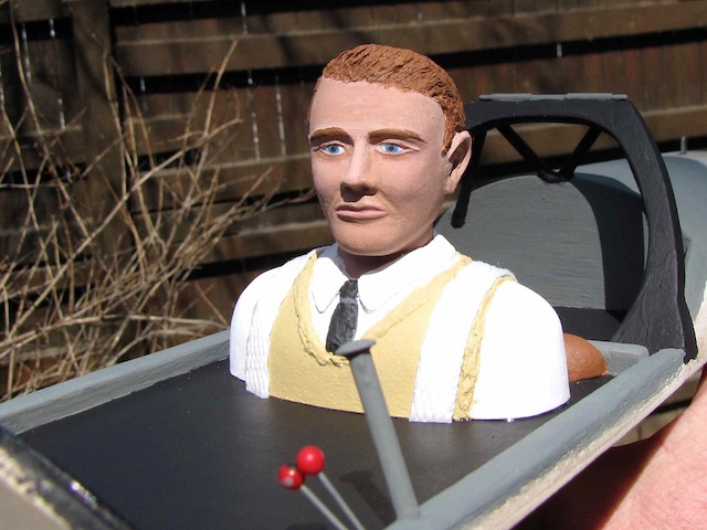
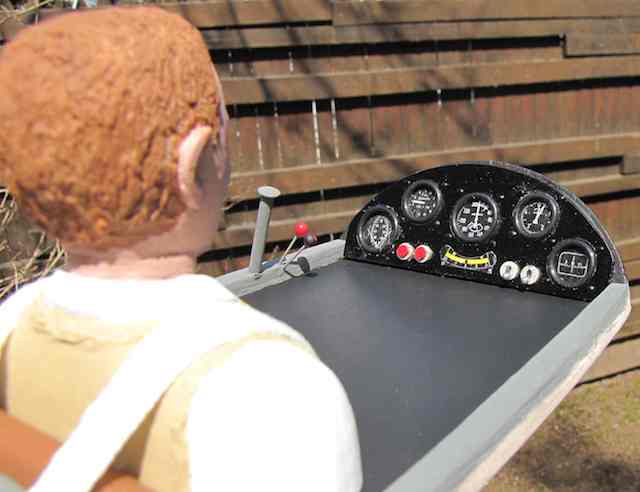
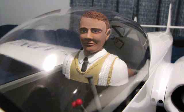
A Bit More on Keith's SparrowJet
Just about ready to mount the canopy so I thought I'd take a couple of shots of "Fred". I thought he came out pretty well for starting with a Williams Bros pilot. Also included is a picture of the real Fred. 
All the detached parts are covered along with most of the fuselage. I still have to cover the stub center section and jet housings. I keep hoping for a dry, windless day to spray paint the exhaust tubes and pitot stinger. I may have to give up and just do it in the garage. This will probably be my last missive, so the next time you see it will be on the table at Toledo. Keith I just got back from test flying the Sparrowjet. I elected to go with the larger wheels and no pants. I don't think it would have mattered as it lifted off the grass in about 40'. Not rotated, lifted, just like a taildragger should do. Reasonable speed considering the thick airfoil, about 75-80 mph, but will stay in the air comfortably at 1/3 throttle. Did rolls, several loops and a pretty hard mock pylon turn without any groans/crunching/splintering sounds from the wings, so I guess my spar design to compensate for the two 2.25 holes for the fans is adequate. It won't stall turn as there is no draft over the rudder, and the snap roll was petty mediocre for the same reason. After flying it a while I decided it is a little tail heavy as the elevator is quite sensitive and requires NO down for inverted. I can't move the 4s 4.0Ah pack any father forward, but I can go to the 5.0Ah pack to get the CG change. I flew a 4.5 minute flight and consumed 2.3Ah out of the 4Ah, so the efficiency of the airframe/EDF/motors is apparent.mYea!� With the 5Ah pack to get the CG forward, that should let me have 7-8 minute flights. I will do more testing to get the CG and control throws tuned, but it's on the road to MidAm. Keith I am pleased with the way it flies. Like I said, it behaves like a modest sport aerobatic model. Power consumption is another thing. I just did some relative performance estimates. I would put its performance between the Stomo and the Sausewind in terms of ability. Both of those planes average 40 watts per pound for a flight. For example, the 7.5lb. Stomo can do rigorous aerobatics for 10 minutes on 8 A123s, with plenty leftover to taxi back. So 2 x 60 = 120 amp-minute, so average current is 12 amp. At 3 volts per cell, that's 3 x 8 x 12 = 288 watt, giving 288/7.5 = 38.4 watts per pound. The Sausewind is very similar in average current and power loading, but can't do anywhere near the aerobatics of the Stomo. Today's flight on the Sparrowjet lasted 6.5 minutes and consumed 4 Ah of the 4S 5Ah pack. So average current is 4 x 60/6.5 = 36.9 amp. At 15 volts for the 4s pack, that's 554 watts. The Sparrowjet weighs 6.2lb. with the larger pack, so the average power loading is 89 watts per pound. About 2.3 times the equivalent power consumption of the Stomo for far less aerobatic performance. But the Sparrowjet is not the Stomo. They live in different worlds, and not everything should be measured in terms of efficiency. The Sparrowjet is to be admired and enjoyed for the strange, quirky creature that it is. I just wish I could have a blue sky behind it. It was spooky at times flying it against the 100% overcast. Fortunately it is well-mannered and flies at a modest speed, otherwise I would have landed earlier. Take care,
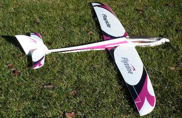
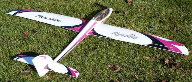
Flyzone Rapide Performance Glider EP Rx-R Review
Specifications (from the Tower Hobbies' Web site)
Wing Cube Loading: 11 (Ken's computation)
I bought the 60 inch Rapide after seeing a new product announcement in Model Aviation. I have been very impressed with the performance on the first six flights. There is "rip it out of your hands" power and the climb angles are well above 45 degrees. The aerobatic performance is outstanding, with or without power. I haven't been out in any thermal weather yet, but I think it may do a bit of thermalling on the right day. As is typical of the Flyzone product line, it is a very complete, receiver and battery ready package. It can use a minimum of 4 channels, but it really comes alive with 5 or 6. It goes together quickly with a few screws. A "Y" connector is included for the ailerons. The bottom of the wing has stripes for easy identification. The decorations use a different technique that is very durable. It utilizes the ubiquitous 3S 2200mAh LiPo battery. 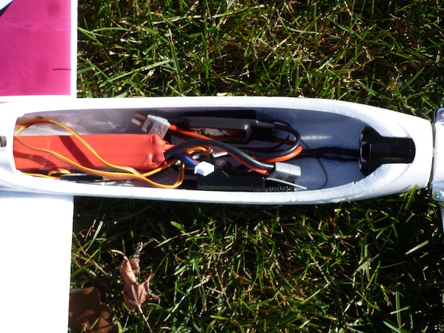 Access to the battery is through a hard molded canopy with a unique twist latch. 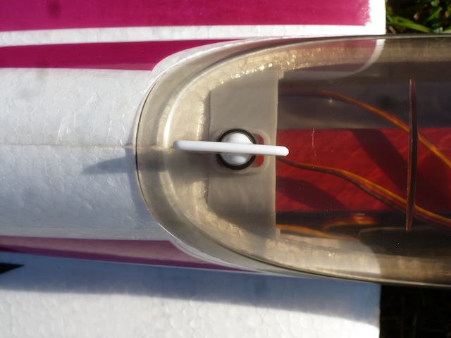
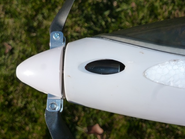
There is a molded white plastic hard shell surrounding the nose. There is plenty of ventilation for the motor and battery. On mine there was a bit of flashing on the molded wing joiner. A touch of sandpaper took care of that. I wondered how there was enough strength to keep the wings together until I held the wings up to the light. There is a complex molded reinforcement imbedded in each wing panel as well as a carbon fiber spar. The fuselage has a similar spar running down the length. Pitch is controlled by a stabilator with the elevator servo in the tail in a hard plastic molded assembly. There is an option for splitting each aileron, adding 2 servos and having flaps. I used a Tactic receiver and a Tactic 850 transmitter for control. On the initial set up, I used the single short antenna Tactic TR624 and set up flaperons instead of cutting the ailerons and installing 2 additional servos. Two 3 inch extensions are required if you set up for flaperons. I set the stabilator to the molded neutral mark. I recommend that you make sure you have a second person to do the initial launches. The first flight was "emotional". At full throttle it ripped out of the launcher's hand (eventually a good thing) and then started to dive. Full up elevator got it pointing to the sky as I added up trim. It wound up needing full up trim. So far so good. I then noticed that as I flew farther away I was getting "hit" with intermittent operation. I got it safely back on the ground. The original receiver had worked well in other aircraft. I replaced the receiver with a dual antenna Tactic TR625 thinking that all the carbon fiber was effecting reception. The intermittent operation problem was solved. I then moved my attention to the stabilator. Removing the stabilator I disassembled the stabilator mounting assembly. A few turns on the stabilator pushrod clevis got the stab back to what was the flying position with the transmitter elevator trim at neutral. Should you have to do this on yours make sure to check that the stabilator movement is not restricted (stopped) when moving up with the new neutral position. 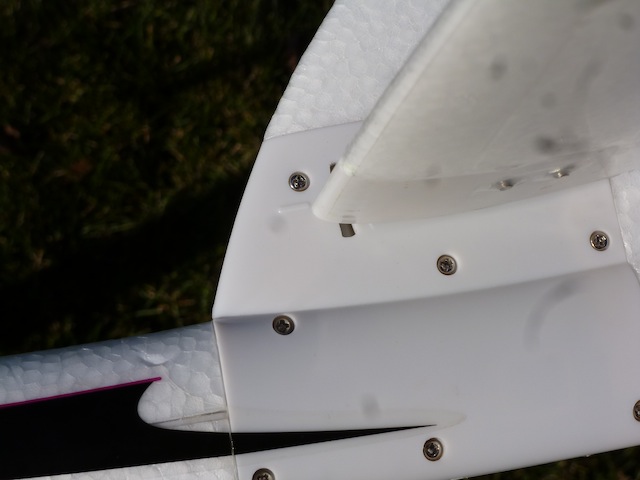 The Rapide is slippery, both in the air, and on the ground. A couple of pieces of white "hook" Velcro stuck to the side of the fuselage made it easier to hold on to the fuselage just before launch. Back to the field to check things out. Elevator trim and positive control was now perfect. The Rapide does great sport aerobatics. Under power it climbs like a home sick angel or goes fast in level flight. I can easily get 6 climbs to altitude on a single charge. Now it was time for a landing. All of the characteristics that make it fly so well make it tough to get back to the ground. It just keeps flying. The first approach just flew past me. On the next approach I deployed the flaperons to the first position. This got it slowed down a bit but still pretty fast. On the next approach I deployed full flaps. This was much more manageable for a landing. I then decided to try spoilerons instead of flaps. With the ailerons (spoilerons) moving up, the sink rate improved considerably. I am now experimenting with spoilerons to get the Rapide down quickly and then moving directly to flaperons to slow down for the landing. Of course pitch needs to be mixed in as the spoilerons / flaperons are deployed. The Tactic 850 handles these easily. I also used the Throttle Cut program to have a disarm switch. It is best to experiment to dial in the Rapide to your flight preferences. I really enjoy flying the Rapide. It has proven to be very aerobatic and very durable. It fits easily, fully assembled, in a mini van or small SUV. With only one bolt to get the wings off, it can go together quickly at the field. Give it a try. Joe Hass
 January EFO Meeting with Some Follow-ups The January EFO meeting was well attended on a very rainy Wednesday evening, January 11, 2017. It was the first time in anyone's memory that we had a thunderstorm during a January meeting here in southeastern Michigan! 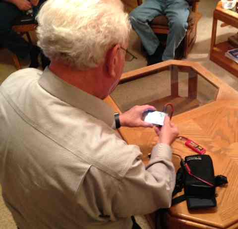 Bob Blau lead off the meeting by sharing his new ISDT 608 compact charger. The charger is a 150W, up to 8 amp, compact multi-chemistry charger. It has a 2.4" color LCD. He demonstrated how the scroll wheel is used to navigate through the menus. Even though the unit is compact, 88mm (3.5&quuot;) x 58mm (2.25") x 21mm (0.75") (excluding protrusions), it seems to pack the ability to do a pretty good job charging. We all saw the value of a charger like this to 'take on the road'. "The sc-608 can be ordered from Banggood for $39.99. "Ken asked if the firmware could be updated. Bob said he wasn't sure. "The following day, Ken found out that it could be. There is a device known as the scOs The firmware upgrade cable that allows firmware updates. "More on this charger can be found on RC Groups. 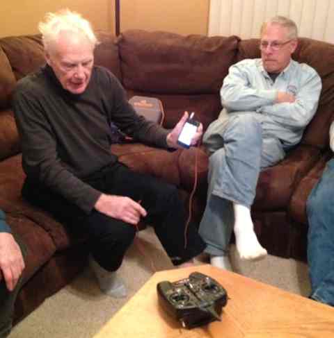 "Arthur Deane purchased a cute, little Cub at the Midwest RC Society Swap Shop in November 2016. It came with a small 'problem'. Arthur uses Tactic radio equipment. The small plane was set up with very small servos that work with Spektrum radio gear. "He solved the 'problem' by purchasing a Spektrum DXe DSMX Transmitter. "It is programable, using a computer or, better yet for the flying field, a smart phone and optional cable. "He also purchased a 6 channel AS3X Spektrum receiver to go with it. He was impressed with how Denny Sumner's little planes handle the wind with this type of receiver, so he wanted one. "To keep his new transmitter safe, he also purchased a very nice case for it. (The case is shown on couch in the photo.) 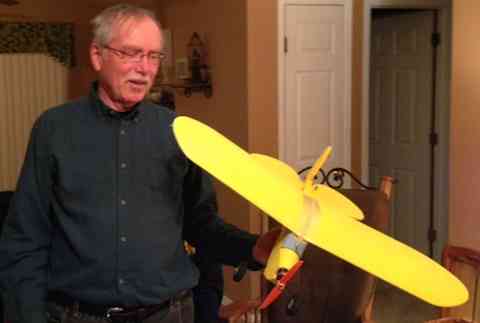 Richard Utkan, EFO vice-president, shared his Lazy Cub. It is produced by KensCADmodels.com. Richard did a balsa modification on the battery compartment to hold a larger 2S LiPo. The kit includes pre-bent landing gear, preformed wing panels and all CNC cut foam parts, carbon fiber elevator spar, laser cut firewall and control horns, pushrod guide�tubes, wing hold down dowels, and rudder hinges. This is the second one of these nice flying models in the EFO club. Roger Wilfong has one. He brought the model with two rubber bands holding on the wing, just for show and tell. During the meeting the members heard a loud pop. One of the rubber bands had snapped. Richard mentioned that he'd purchased them from the fellow at the Toledo RC Expo that sells rubber bands. Ken Myers said that he had used the same rubber bands and had found them unacceptable. They 'snap' easily for no reason at all and can't take being out in the sun. Ken said that it was back to Sig rubber bands for him. You get what you pay for. 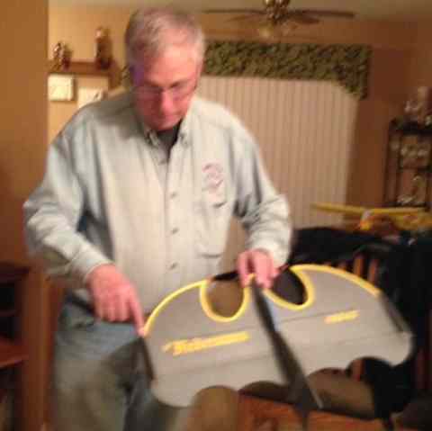 Roger Wilfong brought his John Hoover designed Das Fledemaus. The Das Fledemaus Foamy RC Depron KIT is available directly from Flightline Hobby. The foam itself is black and comes precut to the 'bat' shape. Roger painted the leading edges and other yellow trim. It uses the ubiquitous 250 brushless motor. It was also noted that Flightline Hobby has moved to its new location; 3039 Baldwin Rd. Lake Orion, MI 48359. The phone number is 248-814-8359. 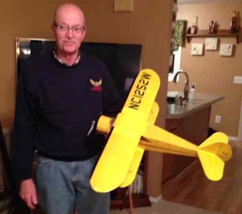 Denny Sumner brought his beautifully finished WACO SRE. It was built from a Manzano Laser Work's semi-kit. It was designed by Peter Rake and originally used a GWS IPS power system. Denny's version, with a 2S 450mAh LiPo battery, weighs 7.5 oz. It is covered with UltraCote ParkLite yellow and AirBorne Models' LighTex black.
Denny has a build thread on RC Groups for this plane. Keith Shaw noted that the Airbourne Models' ToughLon is also a good covering.  Hank Wildman had several questions about checking the health of LiPo batteries. Several members tried to answer his questions. He also shared how he made landing lights from the LED hat visor lights from the Dollar Store. Pretty cool, actually. He wanted a good source for micro switches. Dave Stacer sent him a source the following day. I've provided his reply for those who might be looking for some micro-switches. Here is what Dave sent Hank:
I think these are the switches you are looking for.
Slightly different tab on them. I have ordered items from this company before. They are in China, they accept paypal and I've never had any trouble ordering from them. It might take 15-30 days to get your order. Dave Stacer 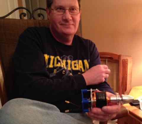 Dave Stacer shared a motor mount standoff. He drew up the file, sent it to the Northville library and they printed it on their 3D printer. The cost for the part was only $1.00. The standoff looks like it should come in quite handy, and Dave said that the whole process was quite easy using a free program from the Internet.  Ken Myers showed a problem he had with an AOK 3 in 1 150W Discharger, Voltage Tester, Balancer For Lipo Battery that he has. The two wires broke off the connector going to the circuit board with the lights attached to it. The wires are tiny, and he must have handled too roughly - - - NOT!!! Keith opened up the case, and he and Ken decided the best 'fix' would be to use a heavier gauge wire to replace replace the thin wire, and then to solder both ends, instead of using connectors.  Next Ken showed a Harbor Freight CEN-TECH 11 FUNCTION DIGITAL MULTIMETER with AUDIBLE CONTINUITY, Item 61593. He noted that it seems to be as accurate as many of the meters he has, and that the thermocouple temperature feature, reading only in Celsius, seems to be reasonably close. He had added this meter to his 'collection' because of the price. It was on sale and he had a coupon. He paid $17.99 for it, plus Michigan sales tax. Ken discussed why someone might want to know the resistance of their battery over time, as it indicates the relative 'health' of the battery. 
Dave Stacer photo Ken briefly shared his discharge 'rig' for determining pack resistance. It consists of a switch, an indicator/brake light bulb and two 12V Halogen bulbs in parallel, which are controlled by the switch. The indicator/brake light bulb is in parallel to the two Halogen bulbs. His test recording instrument for volts and amps is his Emeter II. He presented some battery resistance numbers that he had calculated for a 3S A123 pack. He wondered why one set of calculated resistance number was quite a bit different from the other two sets. The resistance figures that were notably higher were calculated during a discharge from a full charge, 10.93V. Remember this is an A123 pack, not typical LiPo pack, so don't let the voltages fool you. 'The other two were from around 10V on the pack. At first, Ken thought the difference with the fully charged pack having a higher calculated resistance was because he did it at about 220C, while the other two discharges were at about 150C. Keith said that that was not the cause! He noted that when A123 packs are fully charged they yield a higher resistance calculation than when they have been run down a bit. He also noted that the resistance calculations diverge from the typical resistance again as the pack approaches empty. The following day, Ken found a reference to this phenomena on the Battery University site.
Also, the following day, Ken started to put that to the test. 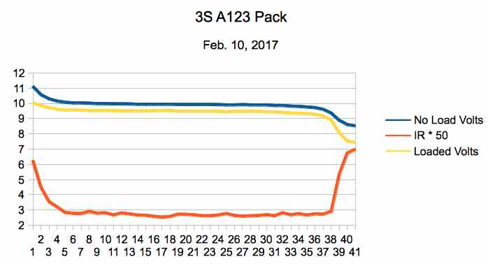 The graph shows the calculated battery resistance from 'fully charged' to 'almost empty' for an A123 pack. Several different methods were used to calculate the battery resistance, and the average of the methods was used for the graph. No load and loaded volts are also shown. It took 4 days to gather the data. The pack temperature was kept as consistent as possible. Discharges were done with a minimum of one hour between them to make sure that battery internal temperature was not a factor in the results. The graph confirms the statement found at Battery University and Keith's extensive, and unquestionable, knowledge It was the first time that Ken had run across this information, and it was a real learning experience. Ken is unsure as to why this information is not more widely known. Ken then demonstrated how the calculated battery pack resistance numbers could be used with the DC Circuit Construction Kit to provide visual verification of the resistance calculations in a simulated circuit. 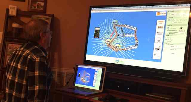
Ken Myers demonstrates inputing battery resistance values in the DC Circuit Construction Kit. A video of Bruce Simpson calculating a battery's internal resistance was shown and then discussed.
The evening ended with refreshments and general discussions. It was really a great night. To Reach Ken Myers, you can land mail to the address at the top of the page. My E-mail address is: KMyersEFO@theampeer.org |