 |
Flying High With Electric Power!
The Ampeer ON-LINE!
February 1999
The Club Newsletter of the Electric Flyers Only, Inc
AMA Charter 2354
Walled Lake, MI, USA
Editor: Ken Myers
Fly the Future - Fly Electric!
|
What's On This Site:
Site Table of Contents
| President: | Vice-President: | Secretary/Treasurer: |
| Ken Myers | Richard Utkan | Debbie McNeely |
| 1911 Bradshaw Ct. | 240 Cabinet | 4733 Crows Nest Ct. |
| Walled Lake, MI 48390 | Milford, MI 48381 | Brighton, MI 48116 |
| (248) 669-8124 | (248) 685-1705 | (810) 220-2297 |
 |
| Board of Directors: | Board of Directors: | Ampeer Editor |
| Jim McNeely | Jeff Hauser | Ken Myers |
| 4733 Crows Nest Ct. | 18200 Rosetta | 1911 Bradshaw Ct. |
| Brighton, MI 48116 | Eastpointe, MI 48021 | Walled Lake, MI 48390 |
| (810) 220-2297 | (810) 772-2499 | (248) 669-8124 |
| Mailed Ampeer subscriptions are $10 a year US & Canada and $17 a year world wide.
FREE on-line! |
| The Next Meeting:
Date: Thursday, February 4 Place: Ken Myers's House Time: 7:30 |
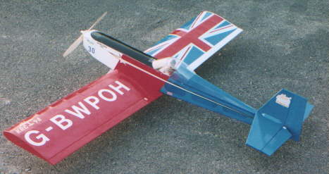
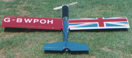
Sig Four Star 40 Conversion
Dereck Woodward, 11159 Captains Walk CT, North Potomac, MD 20878
Phone: 301 309 0140 E-mail: weekendpilot@juno.com
My e-flight conversion of the Sig Four Star 40. Weight
5 3/41b. Built as per plan apart from the modifications to take the newpowerplant - From the front end:
A way cool balsa cowling instead of the fuselage side cheeks in the kit. 1/8” firewall instead of 1/4”. Fuselage doublers cut down extensively to provide former location and wing seat. F2 mostly missing. 1/16” ply nicad platform, mounts nicad just above the wing with Velcro. Top hatch from just aft of firewall to just ahead of cockpit, made from light balsa with locator tabs at front, rubber band hold-down at rear. Receiver and fuselage servos (FMA S200’s) aft of wing aperture. Fuselage ply underside sheeting from wing to tail replaced by small cross members.
Ailerons driven by wing mounted FMA S200 mini-servos instead of a centre servo and torque rods.
The model is covered in Fibaflim (similar to Micafilm). UC is the kit item - a tad short for 13-inch props.
Though some ply was eliminated, the fuselage was made from the Liteply kit parts
- there was no balsa for ply substitution. The wing was built "out of the box" apart from the aileron drives.
Motor - MaxCim MaxNEO 13Y, 3:1 gearing on 20 cells. The MaxCim Controller
uses a tap off the ten cell point as a BEC power supply - this has worked flawlessly throughout, is rated for 3A and manages four
S200 mini servos with no problems. The controller mounts on fuselage floor above the landing gear, with a fuse in the line to the
motor and an extension lead back to the receiver.
Power is typically around 34 amps on a Zinger 13 x 6-10 wood prop on 20 cells
680 watts input power on my Astro Wattmeter, though over 40A peak has been run on a 12 x 6-10 Zinger on 2.5:1 ratio. It was
also flown on 12 x 6-10 and 12 x 8 Zingers, performance on an APC 12 x 8 prop was not as good as anticipated. The motor has
exceptional speed control characteristics, which is good, as the model seldom needs full power, apart from utilising its considerable
vertical performance.
The model is fully aerobatic, limited only by a reluctance to spin and needing a lot
of work to knife edge decently. It can be flown through large or small maneuvers -just like a wet power Four Star 40. There are
no nasty tricks awaiting the unwary. This is a very honest flying model. Take off and landing characteristics are vice-less, the
model making an ideal introduction to flying with a high power electric set-up. Flights on 20 2000mAh cells run out to six minutes
of continuous aerobatics, flown in turn-round fashion with maneuvers at centre and either end of a display line, then maybe a
minute to drop into the landing pattern and fly a circuit or two.
In answer to what are almost inevitable questions in the paper magazine world -
she will not thermal, nor will she fly on seven cells (though the MaxCim brushless is quite happy to perform efficiently on seven
cells, at a somewhat lower power output) :-).
Early in October, I took her to a local wet power club picnic, and put on a
five-minute demo flight.
After I took off, rolled inverted and went vertical, they stopped talking about
electric models being underpowered. After five minutes of aerobatics and most of the landing pattern inverted for the heck of it -
that’s one group that takes e-power a little more seriously now.
"Four Stars" to the Four Star 40 for being a DGA (Durn Good Aircraft)! Five
Stars to MaxCim’s Tom Cimato for putting up with the endless questions as I prepared to make the leap from 10 cell to 20, and
for supplying a superb motor system for sports flying.
The "registration" is my custom AMA number, a birthday present from
Sue. GB (Great Britain) WP (weekend pilot) and OH (over here) - my columns in RCMW and EFI. (Clever Dereck km)
Return to "What's In This Issue?"
DIHEDRAL - How Much is Enough?
by Clay Ramskill
From Loooops & Lies - Newsletter of the River Valley Flyers of Central Wisconsin
Editor: Rich Ida
Like most things in the aerodynamic world, the answer to the above question is -
"it depends". It depends on what you want from your plane; how maneuverable or how stable you wish it to be in
the rolling axis, whether or not you desire the plane to roll when you deflect the rudder, whether or not you wish the plane to
tend to self right when its upset from wings level.
In general, the more dihedral an aircraft has, the more it will tend to self-right to
wings level when upset from straight and level flight. This little bit of roll stability makes the plane easier to fly because the pilot
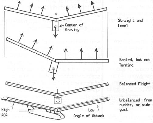
doesn’t have to be constantly fighting to maintain wings level. Note the top two drawings in the figure - once
we are no longer level, the lower wing is effec-tively a bit longer, and the lift forces, forces on the lower wing are pointed more
straight up. Also, since the figure shows a high wing plane, the CG of the plane is offset toward the high wing. All these
situations tend to force the plane back to a wings level condition initially, before the plane begins turning or skidding sideways.
But the conditions described above won’t last long. Also note that we now have
the lift forces on the higher wing pushing sideways; this will cause the plane to skid sideways, turn, or both. Assuming no
corrections from the pilot, what now happens is largely dependent upon the size of the rudder/fin combination! If the fin/rudder
area is just right, the skid continues just enough for the dihedral effect of the wing to return it to wings level. Too much area in
the fin/rudder, and we turn without skidding. Centripetal force from the turn negates all the self-righting effects, and we fly in
balanced flight, but in an ever in-creasing wing and nose-down spiral - this is called spiral instability. Too little fin/rudder area,
and the skid continues even as we pass wings level, resulting in over correction, and the plane rolls and skids, oscillating like a
drunken sailor - this is called Dutch roll.
Although the above discussion is more important to glider and free-flight pilots, it
brings us to look at how dihedral affects a plane in skidding flight - and the good and bad sides of the dihedral effect.
Note in the figure what happens to a plane with dihedral when in a skid, or
unbalanced flight. This condition can occur with the pilots deflection of the rudder, or when a wind gust hits the plane from the
side. The large discrepancy in angle of at-tack between the two wings causes the plane to roll away from the direction of the
skid.
The dihedral effect is beneficial in self-righting, gives us roll coupling with rudder
application, and unfortunately, also gives us roll away from a side wind gust. Incidentally, sweeping a wing back also gives us
dihedral effect - with about 5 de-grees of sweep being equivalent to 1 degree of dihedral.
While roll coupling is essential to a trainer with no ailerons, its not good for
acrobatic and combat aircraft. Most acrobatic and pattern models will have no dihedral. Military planes, with swept wings for
speed, often use negative dihedral to counter the dihedral effects from the wing sweep - the Harrier, A7 Corsair, and C5
transport come to mind.
And while trainers usually have quite a bit of dihedral, and are wonderfully stable
in normal flight, we’ve all seen them turn vicious in a gusty cross wind, during take off and landing, and even while taxiing on the
field.
How much dihedral is enough?? For most of us, then, the an-swer is - Only
enough to give us the roll stability we need, commensurate with our flying skills!
Return to "What's In This Issue?"
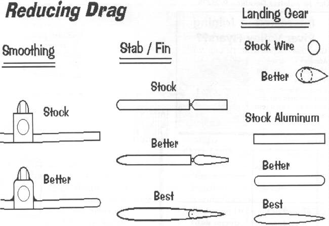
REDUCING DRAG
by Clay Ramskill - From the same issue of Loooops & Lies
This subject is tough, assuming we want to stay clear of complexity. To get into the
nitty-gritty of drag reduction, we need a wind tun-nel, some heavy computations, and a whole bunch of witchcraft!
We’ll stick to some more basic principles, and leave the name dropping and number
crunching to someone more learned than we are!! We do, however, have to make one dis-tinction -- drag due to lift. That is
pretty much separate from the rest, because it’s strictly a function of lift -- the more lift we need, the higher the angle of attack
our wing must operate at, the more lift drag we have. And once our wing area, shape, and airfoil are established, there’s really
only one control we have, and that is the weight of the plane.
Put simply, the heavier the plane, the more this form of drag will degrade
performance, throughout the speed range!
Having gotten past that, there are several other drag components to look at -- skin
fric-tion, form drag, and interference drag, as well as cross-sectional area.
Cross-sectional area is easy. The more air you have to push aside as you go
through it, the more drag. We need to keep fuselages rea-sonably slender and airfoils reasonably thin. But the size is not nearly as
important as shape. Form Drag: Good "streamlining" is an area where we can really see some results. What we’d
like to see is every component of the plane shaped like a good symmetrical airfoil - or like a drop tank as seen on jet aircraft. At
the speeds we’re interested in, a really sharp point in the front is not necessary (that’s what you see on supersonic planes!). What
is desirable is a nice smooth curvature.
Where we DO want the “pointiness” is at the rear. A good, smooth, continually
tapering curve ending at a relatively sharp trailing edge or point. The main thing to avoid is abrupt or angular changes in the
airflow.
Retracts: Easily the worst contributor to drag is the landing gear. Fixed
gear drag can be reduced by wheel pants and cuffs on struts -- but retracting gear is the obvious solution. There are, however,
weight, complexity and expense penalties
Now, let’s look at skin friction. First, the less skin, the less friction!
Rounding corners not only cuts form drag, it cuts the skin area. Round forms enclose the most interior volume with the least skin
area. A smooth skin cuts drag -- dirt, rough covering overlaps, and covering wrinkles all in-crease drag. You won’t do much
better than good sanding and Monokote! We should point out that sharp corners, even when aligned with the air-flow, will tend to
increase turbulence and produce more drag. A rounded fuselage is less draggy than square -- the same goes for wing tips.
Interference Drag: We did a nice little wind tunnel experiment in school:
we measured the drag of a fuselage, and then the wing. Then we put in the wing and fuselage attached together. The
combination had extra drag beyond the sum of the components!
The interference caused by projecting objects (like wings, landing
gear, gear struts, stabs, etc.) can be reduced, usually by the use of fillets. These were quite pronounced on WWII fighter wings,
as on the Spitfire and P-40 and just rounded off the interior square corners, carrying the rounding well aft of the wing. You’ll see
these on pattern and racing planes.
Projections: The best solution to projections is --get rid of them! Retract the
landing gear, hide the control horns, enclose the radio antenna, counter-sink the bolt heads, etc. Cowl in the engine, use an
enclosed muffler. Look at a competitive pat-tern plane -- you’ll see all of these features. Like most things aerodynamic, drag
reduction involves many details, all of which add up in achieving your goal "If you want to go fast, get out the sandpaper."
Yep, but remember, we need both a smooth skin AND a smooth form!
Diagram of Drag and Drag reduction
Return to "What's In This Issue?"
Meet Ralph Weaver - NEAC President
As the National Electric Aircraft Council enters its fifth year, I thought it
would be a good idea to introduce you to its current president, Ralph Weaver. Ralph needs no introduction to many of
you, as he is a well known and expert electric flier, both sport and competition. He also hosts a very nice electric fly near
Indianapolis. The following is from the September ‘98 NEAC News, edited by Doug Ward, R.D. Box 189, Irwin, PA.
NEAC is the AMA recognized SIG (speical interest group) for electric flight. You can join NEAC by contacting Ralph.
Other officers are; vice-president, Bob Aberle, secretary, Tom Hunt and treasurer, Glen Poole. All are very well known
competition and sport electric fliers. Km
I’d like to introduce myself as one who has been inter-ested in airplanes for as far
back as I can remember. Before I could read, I built my first plastic model.
For several years, at the time I was in junior high, I flew combat and Goodyear. As
I got older, other activities took over until the early 1980s when I began to fly R/C. Electric flight began in about 1990 when I built
an ElectroStreak and I have been hooked ever since. I now fly all types of electric planes and compete in Limited Motor
Run (LMR) events.
I’m honored to have been elected the NEAC president. The previous officers have
done a good job in establishing the organization as the AMA Special Interest Group for electric flight and the coming years appear
to be equally exciting and full of promise as our aspect of the hobby grows in popularity.
The mission of the NEAC is The Promotion of Electric Flight. In order to carry out
this mission, we have several goals and issues before us, some of which require prompt attention.
A rules interpretation pro-posal will be submitted to the AMA which limits Old
Timer models to three, and only three, controls: rudder, eleva-tor and motor.
Additionally, we will attempt to expand next (this km) year’s Nationals
program to five days allowing three days for official events and two days for provisionals. This arrangement would permit more
than three rounds of LMR flight and open up time for a sport scale event.
At the Nats, our first goal is to increase participation; the second goal is to raise the
level of technology and skill.
In order to reach these objec-tives I would like to form teams made up of
volunteers for the specific events. One example would be an LMR team which would further de-fine the rules for that aspect of
competition and propose new rules as needed. Simi-larly, we would need a team for Sport Scale and Provisional events. A
Promotions Team consisting of the newsletter editor, the pro-posed web page editor and other volunteers could act in the public
relations domain. The Promotions Team would be authorized to establish an Electric Flight Referral Ser-vice with the AMA. Such
a service would allow anyone who is interested in electric flight to contact the AMA for connection to the appropriate voice of
the NEAC. The key to success in this venture is to find enough persons who are willing to volunteer. Of course, the officers
would coordinate and assist in any way possible.
Please contact me if you have other ideas or suggestions about the future of the
NEAC. It is of great importance to let me know if you are willing to become a mem-ber of any of the teams. Our immediate need
is for the LMR Team, Scale Team and Promotions Team. If you would like to start another team and there is enough interest,
then we will try to do it. Perhaps teams for indoor flight or racing? The amount of participation we get will determine the number
of tasks we take on.
I’m looking forward to hearing from you.
Ralph Weaver, 10783 Northhampton Drive, Fishers, IN 46038
Phone: 317.841.3851 E-mail: weaverr@iquest. net
Return to "What's In This Issue?"
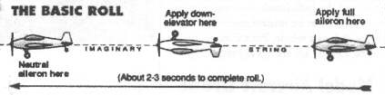
AEROBATICS - The Axial Roll
By Bruce Cronkhite - From the Oct. ‘98 Peak Charge - Newsletter of the Silent Electric Flyers of San Diego
Edited by: Steve Belknap - Web site: http://sefsd.org
The loop we discussed last time is the easiest to do because you use only one
control: the elevator. The next maneuver, and the most used in aerobatic competi-tion, in various forms, is the roll. The roll is
simply a rotation of the airplane about the "Y", or longitudinal axis (as the loop is a rotation about the pitch axis). The
problem is that the roll requires the use of two controls, the roll and the pitch controls, to do it well.
Back in the old days (I was there, ‘cause I’m old too) we rolled our rudder only
R/C airplanes using -surprise- rudder only. Remember that in an airplane without ailerons the rudder is the primary roll control.
But we also used the elevator (stabilizer) to complete the roll at the same altitude we started at. The stabilizer was set at enough
negative incidence to cause a significant pitch-up at high speed. We started the roll from a spiral dive, waited for the nose to
come up, and then applied full rudder. If we were lucky the model would complete a "barrel" roll. It was, however,
anything but axial.
In order to make a roll axial we have to use down elevator the overcome the pitch
trim in the model used to make the model fly normally level.
Models with or without ailerons can be made to roll very axially with the correct
and careful application of down elevator during the roll. Now a competition aerobatic pilot will tell you that you must use rudder
during the roll also, to make the roll perfectly axial, and he’s right. But for our purpose we can do a pretty good job without rudder
if we keep the airplane flying fast- the faster the better.
A roll puts no excessive stress on the model so speed is good. Particularly with a
model that rolls by action of dihedral, the higher the airspeed the higher the roll rate.
When you try to do a roll for the first time, get into level flight at full throttle and
apply full left or right roll command, and hold it. When the airplane is at a roll angle of about 90 degrees start feeding in down
elevator. This is intended to keep the nose up (above the horizon). Overdoing it won’t hurt. You should start feeding in the down
before the model is completely inverted because if you don’t the model will already have it’s nose down by that time.
When the model is past 180 degrees of roll start taking out the elevator so that you
will have a little up elevator when the model is upright again. Don’t forget to continue to hold in that roll command all the time.
The way to screw up a roll is to chicken out and release the roll command at some
point during the roll, or worse, put in up elevator instead of down. The potential consequences of that should be obvious.
The roll takes practice, so repetition is necessary to get the timing of the elevator
application correct.
Doing a good axial roll is fun, and very satisfying if you get it right.
Now do two or three in succession. The old AMA pattern had a maneuver in it
called "Three Axial Rolls". Lots of fun trying to keep them in a straight line.
Return to "What's In This Issue?"
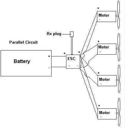
Multi "Engine" Wiring
By Pat Tritle
From DEAF Notes - Nov. ‘98 - Editor: Frank Korman, 9354 Forest Hills Blvd., Dallas, TX 75218-3633
When I first began the design phase for the B-17, I realized the one thing I had to
do was to keep the all up weight of the airplane down to a reasonable level to actually make it work using Speed 400 motors. One
way to accomplish this goal was to keep the battery weight down. Using 1700-2000 mAh cells at 2 oz. each. I’d be dealing with a
maximum battery weight of 16 oz. - if I could do it with one pack. The static current draw using the 2.33.1 gear drives is around
29 amps on 8 cells, so a five minute duration is definitely possible using one speed control and battery.
Using the above data, I chose to connect up the system in using a
parallel circuit. Basically, this means that the negative and positive terminals of all four
motors were connected to the negative and positive terminals at the speed control.
Doing it this way, each motor sees the available voltage from the battery (9.6V)
while the current draw per motor (approximately 7.25A) times the four motors gives the 29Amp static draw mentioned earlier.
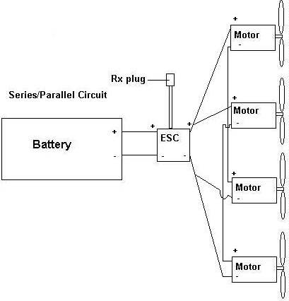
Now, had I stayed with the original direct drive concept, that would have produced
a current draw around 45 amps using the same parallel circuit. To accomplish this at a reasonable current draw, I would have
used a series/parallel circuit. In this set-up two groups of two motors would have been
wired from controller position to 2 motor negatives.
The two groups of motors would then be jumpered motor negative to motor
positive. Using this system the cell count also doubles since each motor in the pair only sees half the available voltage from the
battery. As you can see, using the gear drives reduced the battery requirement from 16 down to 8 cells for a net savings of
around 12 oz. after you add the weight of the 4 gear drives.
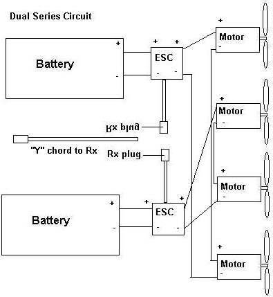
Another alternative is the dual series circuit
which would require 2 speed controls and 32 cells. The motors are wired from speed control as in the previously described
series/parallel circuit but only two per controller. The advantage would be that smaller cells could be used for even better duration
but the complexity comes up by essentially running two systems. The main reason I didn’t use this system was I couldn’t find a
place to load 32 800 mAh cells and still make battery removal practical.
I’ve included the diagrams for each of the 3 setups which were taken from RC
Report Magazine in a two-part article by Gregg Gimlick in the March and April ‘98 issues. It’s a good write-up. and if you’re
considering a twin (or more) "engined" airplane. it’s a good source of information to pick the setup most suited to your
project.
Pat Tritle, 10313 Snowheights NE, Albuquerque, NM 87112. (505) 296-4511.
Email = Dtritle@salud.unm.
(Please note that I replaced Greg’s drawings with my own. Please check
out Greg’s article, and also the article by Keith Shaw on Twins. Keith’s article can be found at the EFO web site -
http://members.aol.com/KMyersEFO Km)
Return to "What's In This Issue?"
Spring E-fly - Rockville, MD near D.C.
From: Dereck Woodward email: woodwadd@erols.com
Event date is Sunday 30 May, the field will be open on the 29th. Mostly grass, with
one tarmac runway if the wind is right. Minimum comps. Maximum Fun!
Site is at 600 Gude Drive East, Rockville MD. Map and flier available in early 99 from Dereck Woodward at
weekendpilot@juno.com
Site is in suburban area, close to I270/I495 (Washington Beltway). Several fast food restaurants within minutes.
Wife and/or kiddies get fractious? Metro station, and hence Washington DC, close by, also shopping and a movie theatre.
No camping on site, but there are some sites within 10 miles, area is awash in motels.
Yours in modelling, Dereck Woodward
Return to "What's In This Issue?"
Building Light
By Russell Bennett
From the Baltimore Area Soaring Society News
There is nothing quite like the feeling of watching the glider that you just tossed into
the air get sucked up by a small energetic thermal. This is, for me, one of the real joys of handlaunch glider flying. In an effort to
have more fun, I try to build planes that thermal easier. Now, when it comes to indicating lift and staying up in light lift, lighter is
better.
How do you build a light airplane? Two areas I have often wondered about are
wing skinning adhesives and covering materials. In the past I had read things like "Micafilm is the
lightest covering" and "diluted yellow glue is lighter than epoxy", but I had never seen any numbers. I decided
to do a little research.
I cut squares of balsa wood and covering materials, each approximately 20
square inches. The dimensions of each piece were measured and the area calculated. Using a balance which has a resolution of
0.0001g, I started weighing.
For the liquids, I would weigh a piece of balsa wood, applied the adhesive or paint,
allow it to dry, then weigh the wood again. The weight of applied liquids will vary depending on who does the applying, however,
the relative weights of the different materials should remain the same.
The results were interesting. Take Micafilm as an example. When used on an open
structure Micafilm is very light. When used on a sheeted surface where it is necessary to have a continuous coat of Balsarite, it
is actually on the heavy side. You would be better off using transparent Monokote.
For all of the materials tested, the transparent colors were significantly lighter than
the opaque colors. This is due to the transparent colors being tinted with a dye while the opaque colors require a layer of relatively
dense pigment sufficiently thick to block most of the light.
The 3M 77 spray adhesive is an example of now much the weight of coatings can
vary between "just enough to do the job" and "that shouldn’t ever come unglued."
Material Weight (oz/sq.ft.)
- EZ-LAM epoxy on balsa 0.127 oz.
- Diluted alphatic resin glue on balsa (3:1 with water, applied with a sponge roller) 0.086 oz.
- 3M77 spray adhesive (2 surfaces, light coats) 0.037 oz.
- 77 spray adhesive (2 surfaces, heavy coats) 0.143 oz.
- Monokote (opaque: white and orange) 0.250 oz.
- Monokote (transparent: red and green) 0.185 oz.
- Oracover (opaque white) 0.267 oz.
- Supercote (opaque yellow) 0.177 oz.
- Micafilm (pearly white) 0.136 oz.
- Micafilm (clear) 0.073 oz.
- Ultracote (purple) 0.228 oz.
- Lightspan (blue) 0.086 oz.
- Clear mylar w/adhesive (Model Research Laboratories) 0.134 oz.
- Water based polyurathane (one coat applied with a sponge brush) 0.122 oz.
- Balsarite (one coat, needed for applying Micafilm and Lightspan) 0.094 oz.
Return to "What's In This Issue?"
RcCad
From: webmaster@rccad.com
We have released a CAD software for the design of model airplanes that is called
RcCad. It provides a real-time 3D visualization of your plane from 2D views. A free version is available for download
(http://www.rccad.com).
We are a little start-up company with a brand-new product! You may also win a full
version of RcCad. See http://www.rccad.com/WinRcCad.htm ...
Sincerely, The RcCad Team
Return to "What's In This Issue?"
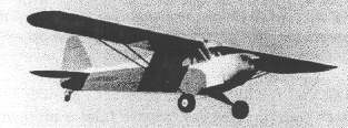
Tale of a 1/4 scale Cub
by Tom Hunt
Via Silents Please Editor: George Myers, 70 Froehlich Farm Rd., Hicksville, NY 11801-3408
The Plane The Power
Many have said that bigger flies better. This can not be more true than with
E-powered models. Well, at least certain "big" models. 1/4 scale warbirds and acrobatic models are still a little out of
reach for E-power. It’s hard to beat a 4 Hp Zenoah at $1.25/gal. 3000 watts (4 Hp) is 100 cells x 30 amps!! and that does not
include "efficiency." However, low powered general aviation aircraft, especially from the 20’s, 30’s and 40’s make
great e-powered aircraft for 28-36 cells. Yes, that is still a lot of money (and weight) but definitely a “do-able” and satisfying
project.
My 1/4 scale Cub started life as a Bud Nosen kit (not the lightest construction mind
you). It was built by an unknown modeler and left hanging in Hank’s Hobbies (formerly of So. Huntington, now defunct) until it
was nearly thrown out. I offered Hank $50 for the airframe some years ago. He accepted, and I got it home. It laid around in my
basement for some years (pre-E-enlightenment). I did manage to strip off all of the old covering to inspect the structure.
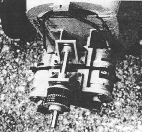
About 1994, I decided to convert it to electric, utilizing one of my newly designed
"big bird" powerplants, the H-1000DP Dual Motor Belt Drive. This unit is rather wide. so converting the model to a
PA-11 was necessary. The PA-11 had a fully enclosed engine, unlike the basic J-3 that had the cylinder heads sticking out the
cowl.
A glass cowl was purchased and two 25 foot rolls of Monokote later, it was ready
to fly. The initial flight was made on a meager 24 cells (12 per speed 700 9.6v motor). It swung an 18 x 8 prop for about 25 amps.
The model weighed in at about 15 lbs. This "underpowered" first flight went well until one of the wing struts came
unscrewed and the right wing dihedral increased rapidly. I thought for a moment I would be able to get it on the ground safely
when a wind gust finished the job. Damage to the cabin and nose was major, but not un-repairable.
After some restructuring, shoring up, and general cosmetic work it was back
together. Self-locking screws were added to the struts to keep the “failure” from reoccurring. Also, 8 more cells were added and
the motors changed to the speed 700 12v versions. The prop remained the same, but it swung a lot faster for all the extra power
available. Current was a mere 20 amps.
The second flight was beautiful. It was off the ground in about 40 feet. Climbed
like a cub, cruised like a cub, landed like a cub. The model now weigh-ed 16 lbs., and with a wing area of 1550 square inches, the
wing loading is a rather high 23 oz/sq.ft. Somehow though, with a model this large (wing chord of 18”) it flies more like 15 oz/sq.ft.
It floats by with just a small amount of power. I swear I can read the label on the prop and still keep it in the air!!. On 1400 mAh
packs I managed to keep it in the air for 8-10 minutes. Some flights had been known to go over 12.
Later, I changed the reduction ratio and prop to a 20x11. I also thinned this prop
considerably to increase it’s efficiency at the low RPM’s it would swing. This change yielded many flights in the 12 minute range,
with lots of touch-and-goes in between.
The model is a joy to fly, not a bad bone in it. Stalls are straight ahead. Ailerons
get "mushy" just like the full scale near stall, so judicious use of rudder is warranted. It has no tendency to spin
inadvertently, although it can be forced. I have not done any real aerobatics with the model, as the wood is really old (I suspect
the model was built sometime in the 1970’s). The inertia of this model is something to behold. It makes all the maneuvers very
scale-like.
This high inertia is also a problem!! With the prop stopped, the model just cruises
right by the landing area. Landing this model where you want it takes a bit of practice. Flaps would help slow it down, but letting
the prop spin a few RPM is actually more drag than a stopped one. Just the “right” RPM must be found for this to happen, but it
is very noticeable when it does.
Recently I have substituted the Speed 700 motors for the more powerful amid
inexpensive DeWalt motors. I am also going to fly it on some new RC-2000 cells. I suspect flight times will increase to over 15
minutes with this combination.
Big models do require some big logistics. Getting the model to the field is the big
one. Even though this model did not cost me very much as far as a “model” goes, the $20,000 van to carry it might deter one
from doing such a project!! I went the cheaper way. I borrow Don Abramson’s van (Thanks, Don) or put it in my $2000 trailer!!
I am sold on big models for electric. One day I will finish my 96" scale
de Haviland DH 98 Mosquito with 40-44 cells and two DeWalt/H-1000’s. Now that will wake up a few people!!!
Regards and best of luck in any large scale project. Tom Hunt
Return to "What's In This Issue?"
Nice B-17
From: John Williams email: qyetfli@home.com
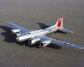
I thought this B-17 belonging, to Jim Sanders, might be of interest. It has
4 Astro 05s and flies on 20 cells and 4 Astro speed controls using Ys. It flies very realistically and is spectacular in the air.
The power system has the two outboard motors are in series, and the two inboards
are in series. Each one runs on a 10 cell pack (20 total). So as not to need an expensive high amp speed control he used 4 of the
cheap Astro 217Ds. Off the Rx throttle connection he used a "Y" with outboards on one side and inboards to the
other. Then two more Ys split that again to right and left motors. It works great.
Return to "What's In This Issue?"
New R/C Auction Online Service
From: David Moran email: admin@flightlines.com
I’ve set-up a new R/C Auction. The URL is
www.flightlines.com/auction/
Return to "What's In This Issue?"
Contributors, I Need Your Help!
The Ampeer wouldn’t be what it is today without the help of my many
wonderful contributors. Thanks to all of you very much.
When you contribute something via email, would it be possible to include a land
mail address and/or your phone number? Not everyone is online, and it would be a great help to those without email. Also, many
folks change email addresses and some addresses become invalid by the time the Ampeer gets published.
Thanks to all of you! You are great!
Return to "What's In This Issue?"
Upcoming Events
Return to "What's In This Issue?"
To Reach Ken Myers, you can land mail to the address at the top of the page. My E-mail
address is:
KMyersEFO@aol.com EFO WEBsite: http://members.aol.com/KMyersEFO/