Ken Myers Change of ADDERESS!
Ken Myers
1911 Bradshaw Ct.
Walled Lake, MI 48390
Phone: 248-669-8124
Ampeer Paper Subscriber Reminder
When subscribing to or renewing the paper version of the Ampeer, please make the check payable to Ken Myers. We do not have a DBA for the Ampeer or EFO. Thanks, Ken
The Jeti Spin 44 & Spin Box
By Ken Myers
Hobby Lobby is carrying Jeti Model's new Spin line of ESCs. They differ from the Jeti Advance Plus series of controllers because they have a data logging feature and cost considerably more. They also use the "optional" Jeti Spin Box to read the data logging done by the ESC and allowing finer tuning of the motor/ESC parameters.
Jeti Spin 44 from Hobby Lobby - $141.70
Measured Weight of ESC, leads, and supplied switch: 1.44 oz./40.9g
Measured Weight of ESC, leads, and supplied switch & screws: with 5 Anderson Power Poles/Sermos connectors: 1.68 oz./47.7g
Measured Weight of supplied 2.5mm "bullet" connectors & shrink tube: 0.18oz./5.0g
According to Table 1 provided on the Spin ESC instructions:
Sustained current [A] (2.2Ah batt.): 44 (According to Bernard Cawley, this sets a time limit for the maximum current. 2.2*60 = 132 amp minutes / 44 amps = 3 minutes)
Batteries NiXX/LiXX/voltage: 6-18/2-6/5-26V
According to Table 2:
Max current BEC [A]: 5
Max. servo number: 8 (There is no note or distinction made between analog servos and digital servos, standard servos and micro servos only the 5-amp current rating.)
Resistance in conducting state [m˝]: 2x 2 (I have no idea what this means. Anyone?)
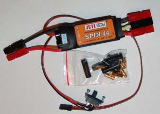
The Jeti Spin 44 amp ESC comes with the three extremely short, short motor leads; two battery leads, a receiver and a switch lead with the switch. It should be noted that the switch has a red paint "square" on it that indicates the On state not the Off state. All of the leads are attached to the ESC unit. There are five "bullet" type connectors supplied with the shrink tubing to cover them as well as a poorly written instruction sheet. The font size used for the instruction sheet is so small as to be almost unreadable. Hobby Lobby should have noted that this instruction sheet is available online at www.jetimodel.cz/eng/navody_en/SPIN_en.pdf. The online version, in the Adobe Acrobat format, is readable and the flow charts are much clearer.
Unfortunately, the instruction sheet contains some very "odd" English phrasing. The information regarding the ESC, actually all of the ESCŐs in the Spin line, covers only two of the fold fourteen pages of the accompanying instruction sheet and the remainder of the information is about setup and use of the ESC using the "optional" Spin Box.
The ESC contains a switched, instead of linear, Battery Eliminator Circuit (BEC) so that it can use higher cell count/higher voltage batteries with no need for an onboard radio receiver battery.
Setup without the use of the "optional" Spin Box is very limited and uses the throttle stick of transmitter to set the options. The throttle End Points can be set and then there are six preset options to choose from.
Mode 1 Acro inrunner: brake off, timing 0-degrees, gradual power reduction when 68% of starting voltage is reached
Mode 2 Acro outrunner: brake off, timing 24-degrees, gradual power reduction when 68% of starting voltage is reached
Mode 3 Glider inrunner: brake on, timing 0-degrees, gradual power reduction when 68% of starting voltage is reached
Mode 4 Glider outrunner: brake on, timing 24-degrees, gradual power reduction when 68% of starting voltage is reached
Mode 5 Heli constant RPM: "this mode is appointed to model helicopters with the claim or constant speed regulation with changing load/unload of the rotor. This mode does not support fast speed changes" (huh?), timing 0-degrees, gradual power reduction when 68% of starting voltage is reached
Mode 6 Heli constant RPM (3D): "this mode is appointed to model helicopters with the claim" (huh?), timing 0-degrees, gradual power reduction when 68% of starting voltage is reached"
Musical tones are played for each mode and repeated five times before moving onto the next mode, which is not noted in the instructions. "Confirmation of the setting is carried out by shifting back the throttle to low throttle position during the tone signals of the factual mode." (Huh?)
Note that the words in quotes are typed directly from the instruction sheet and have been double checked for typing errors.
That is all you can do without the "optional" Spin Box.
To me, the default cutoff voltage set at 68% of the starting voltage is a problem. It is typical for me, when using Li-Po batteries, to fly two flights per battery charge. That second flight would be starting at a much lower battery voltage and the cutoff would be below a "safe" Li-Po battery cutoff voltage. Fortunately, I fly timed flights, based on my battery capacity and average amp draw usage, so it will not be a real problem, but it could be for others.
Setting up and Using the Spin 44
First I set the throttle End Points for my Hitec Eclipse 7 transmitter. There does not appear to be any way to continue the programming without shutting the ESC switch off and the transmitter and then resetting the transmitter throttle to full, turning on the transmitter and then the ESC switch again.
I thought that I had selected mode 2, Acro outrunner, for my BP 3520-6 outrunner. Unfortunately I had not let the ESC play though its 5 tones for mode 1 and had actually selected mode 1, so the timing advance was 0-degrees.
I tested the motor no load and found it to be extremely different (lower) than my data for my TowerPro 3520-7, which had been bench tested with a Castle Creations Phoenix 45 at default settings. It should be noted that my version of the TowerPro 3520-7 is essentially the same motor as my BP 3520-6. Yes, I know the numbers showing the windings are different, but my TowerPro motor tested out to be the Đ6.
I decided to hook up the Spin Box and see what the timing was set for. It was 0-degrees, so the lower amp draw data that I had collected made sense. I reset the ESC, using the transmitter throttle stick to go correctly into mode 2 and the Spin Box then showed a timing advance of 24-degrees, as expected.
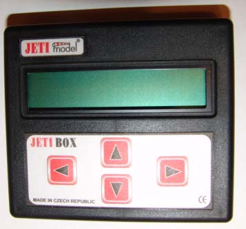
The "Optional" Jeti Spin Box from Hobby Lobby - $48.20
The Jeti Spin Box comes with a 12-inch extension with the same JR-type connectors on both ends and the identical instructions packaged with the ESC in a plastic, reclosable bag.
Using the Spin Box for the first time presented a problem. The instructions say, "Plug in the JR connector of the controller into the plug designated Impuls + - , which is positioned on the right side of the JETI-BOX." The instructions also note, "Do not connect anything to the connector designated with -+ ."
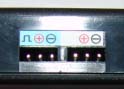
The photo shows a three pin JR-type connector (on the left) with what looks something like a Pi symbol then a + in a circle and a Đ in a circle on a light blue background. The three pin JR-type connector on the right has nothing over one pin then a + in a circle and a Đ in a circle on a white background. (According to what I read on Dec. 9, it is a gray background. If that is so, it is very, very light gray.) There is no connector on the box with a -+, in that order.
I had a 50/50 chance of being right and chose the connector with the symbols on the light blue background. It appears to be the correct one.
When the ESC's JR-type connector is plugged into the Spin Box, the power flight battery connected to the ESC and the ESC switch turned on (moved toward the red square) the display shows the name of the attached controller and, by using the membrane arrow keys on the Spin Box, can provide the basic information about the controller that appears on the instruction sheet.
Pressing the down arrow key, while the initial recognition screen is available, shows a screen that reads MeasureOrSetting. If the left arrow key is pressed selecting MAN, it leads to the menu to retrieve the ESC's logged values from the most recent motor run. If the right arrow key is pressed with the MeasureOrSetting screen visible the Auto set menu is selected and the auto set choice can be selected with the down arrow key. For me, these had already been set using the transmitter throttle stick. Pressing the down arrow key from the MeasureOrSetting screen allows for a review or changing of the ESC's parameters.
I had already run the motor for a no load test and I decided to look at the measured stored values first to become familiar with the unit. I also collected the data after some flights using the Skyshark 4S1P 4000mAh battery and APC 11x8.5E prop and the True RC 5S1P 4000mAh battery. For the data below NL is the no load data, 4S is the data for the 4S1P setup and 5S is the data for the 5S1P setup.
NL - Max. Temperature: 32-degrees C time 02:11
4S - Max. Temperature: 85-degrees C time 08:43
4S - Max. Temperature: 87-degrees C time 7:50
4S - Max. Temperature: 18-degrees C time 00:58 (comparison test 12/08/06)
5S - Max. Temperature: 100-degrees C time 06:59 (note: there is a fault in the temperature in the last data set) This was useful in diagnosing why the ESC cutoff during the 5S flight.
5S - Max. Temperature: 111-degrees C time 06:31
The data demonstrates why the Spin 44 works well with the 4S setup, but doesn't really like the 5S setup.
NL - Min. Temperature: 18-degrees C time 00:00
4S - Min. Temperature: 16-degrees C time 00:00
4S - Min. Temperature: 23-degrees C time 00:00
4S - Min. Temperature: 11-degrees C time 00:00 (comparison test 12/08/06)
5S - Min. Temperature: 11-degrees C time 00:00
5S - Min. Temperature: 20-degrees C time 00:01
I found the 4S/5S data odd, since the ambient temperature was warmer when the 5S pack was flown.
NL - Actual Temperatu: 15-degrees C
4S - Actual Temperatu: 12-degrees C
4S - Actual Temperatu: 11-degrees C
4S - Actual Temperatu: 10-degrees C (comparison test 12/08/06)
5S - Actual Temperatu: 11-degrees C
5S - Actual Temperatu: 14-degrees C
I have no idea what this means. I believe the word Actual needs to be defined or retranslated.
NL - MaxCurrent: --A, --,--V
4S - MaxCurrent: 40,5A, 14,19V, 01:45
4S - MaxCurrent: 39,3A, 14,19V, 01:39
4S - MaxCurrent: 35,5A, 13.11V, 00:53 (comparison test 12/08/06)
5S - MaxCurrent: 43,7A, 17,98V, 03:41
5S - MaxCurrent: 41,7A, 18,88V, 02:11
During the no load test, nothing recorded. It appears that the unit cannot measure amps under a certain low point. It should be noted that a comma is used as a decimal point in Europe.
NL - MinCurrent: 00,0A 19,49V, 02:10
4S - MinCurrent: 26,4A, 13,93V, 08:27
4S - MinCurrent: 21,5A, 14,30V, 05:31
4S - MinCurrent: 33.1A, 12.91V, 00:58 (comparison test 12/08/06)
5S - MinCurrent: 25,8A, 18,27V, 06:03
5S - MinCurrent: 25,4A, 18,41V, 04:33
It is not explained as to what is being recorded here or why.
NL - Max Voltage: 19,95 V time 00:00
4S - Max Voltage: 17,10 V time 00:00
4S - Max Voltage: 16,95 V time 00:00
4S - Max Voltage: 16,87 V time 00:00 (comparison test 12/08/06)
5S - Max Voltage: 21.49 V time 00:00
5S - Max Voltage: 21,49 V time 00:00
This seems to be the battery voltage when it is plugged in.
NL - Min Voltage: 19.26 V time 02:04
4S - Min Voltage: 13,19 V time 00:03
4S - Min Voltage: 13,16 V time 08:10
4S - Min Voltage: 12,91 V, 00:58 (comparison test 12/08/06)
5S - Min Voltage: 17,72 V time 06:12
5S - Min Voltage: 18,01 V time 02:46
It is not explained as to what is being recorded here or why.
NL - Actual Voltage: 12,79 V ("Instantaneous battery voltage." Huh?)
4S - Actual Voltage: 12,76 V
4S - Actual Voltage: 12,76 V
4S - Actual Voltage: 16.81 (comparison test 12/08/06 This one doesnŐt seem to fit the pattern and I have no idea what it is trying to show.)
5S - Actual Voltage: 12,76 V
5S - Actual Voltage: 12.74 V
It is not explained as to what is being recorded here or when. Again, I feel the word Actual is mistranslated. I find it curious that all of these "Actual Voltages" are basically the same.
NL - Off Voltage: 19,75 V time 02:11
4S - Off Voltage: 14,99 V time 07:05
4S - Off Voltage: 14,45 V time 08:30
4S - Off Voltage: 15,33 V time 00:58 (comparison test 12/08/06)
5S - Off Voltage: 19,09 V time 06:12
5S - Off Voltage: 19,29 V time 06:31
This appears to be the unloaded battery voltage when the motor is last turned off.
NL- Motor Run Time: 00:35 s
4S - Motor Run Time: 06:48 s
4S - Motor Run Time: 07:47 s
4S - Motor Run Time: 00:13 s (comparison test 12/08/06)
5S - Motor Run Time: 05:34 s
5S - Motor Run Time: 06:02 s
Appears to be the time the motor was actually run during the session in minutes and seconds.
NL - Power ON Time: 02:11 s
4S - Power ON Time: 09:53 s
4S - Power ON Time: 09:45 s
4S - Power ON Time: 00:58 s (comparison test 12/08/06)
5S - Power ON Time: 08:49 s
5S - Power ON Time: 07:38 s
Appears to be the time in minutes and seconds that the ESC is turned on.
MOTOR POLE NO.: 14 (I set this by checking the BP Hobbies Web site.) and it is the same for all examples.)
Gear: 1:1,0 (default setting) - same for all examples.
NL - Max motor RPM: 14880 time 02:05
4S - Max motor RPM: 31240 (forgot to note time) (note: there is a fault in the U (volts) for the last data given)
4S - Max motor RPM: 09660 time 02:32
4S - Max motor RPM: 08370 time 00:53 (comparison test 12/08/06)
5S - Max motor RPM: 12490 time 02:12
5S - Max motor RPM: 12330 time 04:34
These RPM readings do not match those taken by my Hyperion Emeter tachometer or the Hobbico Optical tachometer. The numbers given by the Spin Box are many hundreds of RPM higher than those shown on the optical tachometers.
NL - Max prop RPM: 14870 time 02:05 (Interesting that this is different than the above when it is a 1:1,0 gear ratio.)
4S - Max prop RPM: 31240 (forgot to note time)
4S - Max prop RPM: 09660 time 02:32
4S - Max prop RPM: 08360 time 00:53 (comparison test 12/08/06 Notice the 10 RPM difference from the motor RPM. IŐve seen this quite a few times and donŐt under stand why when it is a direct drive motor.)
5S - Max prop RPM: 12490 time 02:12
5S - Max prop RPM: 12330 time 04:34
These should only be different when gearing is used.
NL - Errors: U=n, T=n, C=n, I=n (n indicates that the voltage (U), temperatures (T), commutation (C) and current (I) had not been exceeded. A y would indicate it had.
4S - Errors: U=y, T=n, C=n, I=n
4S - Errors: U=n, T=n, C=n, I=n
4S - Errors: U=n, T=n, C=n, I=n (comparison test 12/08/06)
5S - Errors: U=n, T=y, C=n, I=n
5S - Errors: U=n, T=y, C=n, I=n
It can be seen that there was a voltage error during a 4S run, thus the unreal RPM data and a temperature error during the 5S run, explaining the early cutoff.
Next, to learn what parameters can be user set for the Spin 44 I looked at the ESC setting parameters.
ESC Setting Parameters:
Temp. Protection: 99-degrees C (default Đ can be increased or decreased as the user desires up to 110-degrees C. My current setting is now at 110-degrees C)
Brake: Off (can be changed to soft, medium, hard or manually programmed)
Operation Mode: Aircraft (other choices include; Heli normal, Heli(ConstRPM), and Heli(C.RPM) 3D)
Timing: 24-degrees (this is the default outrunner setting but can be changed from 0-degrees up to 30-degrees. My current setting is 0-degrees, which is "strange" for an outrunner. See the "It's a Matter of
Timing" section in my article "Mathematical Motor Modeling, Again" in the December 2006 Ampeer.)
Frequency: 8 kHz (the only other choice is 32 kHz for iron free motors like Tango & Samba)
Acceleration: 0-100% 1,0 s (The instructions note: "On principle - the larger the propeller, the longer the acceleration time value must be. For big reversed motors apply an acceleration time of 2 and more seconds. For model helicopters we recommend acceleration times of 5 and more seconds.")
Accumulator Type: Li-Ion/Li-Pol (the other selection is NiCd/NiMh Đ accumulator is a European word for cell)
NUMBER OF CELLS: LiIo/Po AUTO (there is no arrow on the screen but pushing the right arrow key increments the cell count from 2 Đ 6. My current choice is AUTO)
LiIo/Po CUT OFF V PER CELL: 2,8 (again there are no arrow indications but pressing the left arrow decreases the voltage and pressing the right arrow increments the voltage.)
Off Voltage Set: 08,37 V (this was with a 3S1P pack being used as the power source. When I changed to a 4S1P pack the off voltage was set to 11.37v)
CUT OFF: SLOW DOWN (The other choice is HARD, which immediately stops the motor.)
INITIAL POINT: AUTO (Fixed and chosen. Regulates the stop position of the throttle.)
END POINT: 1,80 ms (This is the Full Throttle value. I did that with the original transmitter setting.)
AutoInc.END POIN: ON from 1,80ms
THROTTLE CURVE: LINEAR (Other choices include Logarithmical if most of the
flight time is carried out within a region of 50% of full throttle and Exponential.)
ROTATION: LEFT (It can be changed to right without having to swap two motor leads. I actually ended up changing this to RIGHT for use with my outrunner.)
TIMING MONITOR: OFF (If this option is turned ON, then the timing is noted as a series of musical tones when the ESC is initiated.)
NOT NOTED in the INSTRUCTIONS!
To save changed settings, turn off the ESC switch.
The Spin Box can be used with a receiver battery instead of the flight battery.
For use with the ESC:
1. Plug the ESC JR-type connector into its position under the light blue background label.
2. Plug a 4-cell NiXX (I don't know if a 5-cell will work) receiver battery with a JR-type connector into the JR-type connector under the white background label and immediately switch on the ESC. Read stored values or setup, as you desire. Reading stored values would be the best option, as some of the setup values require the actual flight battery.
For use as a Servo Tester:
1. Plug a servo with a JR-type connector into the connector where the ESC usually plugs into the Spin Box and a receiver battery into the white background connector on the Jeti Spin Box. The screen reads, "IMPULS GENERATOR" and the options are YES or NO. Pressing YES for the servo I had plugged in read, "IMPULS GENERATOR: 1,541 ms 5,22 V" but I have no clue as to what it is telling me.
2. If NO is chosen, the screen then reads, "SERVO CYCLE: YES NO" If YES is chosen the number of cycles may be selected and OK starts the cycling. It runs through the number of cycles selected displaying some information I am not familiar with.
3. If NO is chosen from the above screen, the next screen reads "SERVO SPEED Tst. YES NO" The high and low positions are selected and then a Servo Speed screen appears with a number like 0.109 s for the servo I tested.
When in the Servo Tester Mode, I really only understand what the Speed Test is telling me.
12/08/06 Recheck of Data Logging
I used a 4S1P Skyshark 4000mAh Li-Po battery that had a bit of runtime on it to check the Data Logging function of the Jeti Spin 44 against the data collected by my Hyperion Emeter and Astro Flight Whattmeter. The Emeter and Whattmeter were placed inline so that all readings could be made simultaneously. I could not compare the RPM reading on this day, as I had to do the test in the basement. The outside temperature was about 20-degrees F/-6.7-degrees C, which is just too cold to set up the video camera to get the optical tach/Whattmeter measurements outside in the sunlight.
I was able to get the volt and amp readings. After "playing" with the Spin Box for a while it seems that the reading to use for comparing is called "MinCurrent", as that appears to be the last current data taken before throttle is shut down for the final time. I watched the Whattmeter and used the hold function of the Emeter just before shut down and captured the following:
Jeti Spin Box: MinCurrent - 33.1 amps, 12.91 volts, time 00:58 (that was shutdown time)
Hyperion Emeter: 31.1 amps, 12.83 volts
Astro Flight Whattmeter: 31.4 amps, 12.5 volts
The Whattmeter and Emeter are within 1% of each other for amps and 2.6% for volts.
The Spin Box differs with the Whattmeter 5.4% for amps and 3.2% for volts.
The Spin Box differs with the Emeter 6.4% for amps and 0.6% for volts.
These seem like relatively small differences overall, yet, it still bothers me.
One thing I did notice was that when using the 5S pack and the ESC goes over temp and starts lowering the power, the lower power is what gets recorded as the MinCurrent before the shut off of the ESC. Also, restarting the motor to "stretch" the landing or taxi back to the pits, changes the saved values.
If data logging is important to you, you are probably better of to use something like the Eagle Tree Systems MICROPOWER E-LOGGER & POWERPANEL (www.eagletreesystems.com/MicroPower/micro.htm).
Just for archiving purposes I've added the comparison run data to the measured data section.
After my initial run through, I had several questions about the Jeti Spin Box. Emails were sent to Jeti@Jetimodel.cz and to Jason Cole at Hobby Lobby.
1st email: Questions about the Jeti Spin 44-amp ESC and Jeti Spin Box.
What is the difference between Min. Temperature and Actual Temperatu? Is either one of them the ambient temperature of the ESC?
What does Actual Voltage mean? The instructions state, ŇInstantaneous battery voltage.Ó What does that mean?
Why would the Max motor RPM: 14880 time 02:05 and the Max prop RPM: 14870 time 02:05 be different on a direct drive motor? The numbers came from one of my "tests."
Does your word "Impuls" mean signal in English? Does the symbol that looks something like Pi mean signal? (Bernard Cawley answered this on RCGroups - it does)
Why are there no instructions about using the Spin Box with a receiver battery?
Why are there no instructions about using the servo tester function of the Spin Box and what the information during the servo testing is telling the user?
Why for Sustained current [A] (2.2Ah batt.) do you designate a battery Ah? (Bernard Cawley answered this on RCGroups and I noted his reply previously.)
What does Resistance in conducting state [m˝]: 2x 2 mean?
The Spin Box instructions note, "Do not connect anything to the connector designated with -+ ." There is no -+ on the Spin Box. What did you mean to say?
Why didn't you say that shutting off the ESC switch or pulling the ESC plug saves the changes made to the ESC programming?
2nd email: Another question about the Jeti Spin Box
I cannot get a reading for the no load current of about 4 amps on the Spin Box. Yes, I held the throttle wide open for more than 5 seconds. What is the minimum MaxCurrent that can be measured?
3rd email: Big Problem
I ran into a HUGE problem this morning with the Spin Box captured data. I was using my Emeter and gathered and held data on RPM, volts and amps at full throttle. It did not come close to matching the data retrieved from the Spin Box. Spin Box data was about 9200 RPM, 37+ amps and unknown voltage (didn't write it down) while the Emeter was 8700 RPM @ ~32 amps. Okay, Emeter could be wrong. Got out my Hobbico Mini-tach and Astro Flight Whattmeter. I continued testing on the same pack and the Emeter, Mini-tach and Whattmeter were very close in readings while with the Spin Box was hundreds of RPM higher, usually 3 to 5 amps higher on the amp readings and usually 0.5v or more higher on the voltage. This is not good and I find it unacceptable. Suggestions?
On November 13 I received an email from Jason Cole that said he passed my questions and comments onto Mike Hines. I have not heard from Mr. Hines.
On November 20 I received the following email from Jeti Model. It did not address the first two emails I sent. I was not very happy with this reply.
"Dear sir,
RPM of motor are measured by incoming frequency to the motor. If it is right set number of motor poles, I do not suppose any significant difference.
Situation with current measuring is more problematic due to method of measuring (voltage drop on power FETS).
In this case is difference up to 10% accepted.
Best regards J.Tinka
JETI model s.r.o.
Kadl‡‹kova 894
742 21 KopŢivnice
Czech Republic"
Conclusions:
The Jeti Spin 44:
The ESC seems to perform well with a 4S1P pack but has caused endless problems with premature cutoff because of going "over temperature" when using the 5S1P pack. The switching BEC seems to be a nice, built-in function. The linear throttle response seems good.
The ESC does not appear to be very accurate when logging data. Without the "optional" Jeti Spin Box, the default settings, using the transmitter throttle stick, are quite limited.
The Jeti Spin Box:
The Box works well to fine tune the parameters of the ESC and is relatively easy to use. I like the idea that it is easy to take to the field to make changes, just like when I use my Emeter with my Hyperion ESC.
There are many unexplained functions and the instructions need a major revision and update to include the servo testing function.
These units are available from Hobby Lobby at www.hobby-lobby.com
Return to "What's In This Issue"
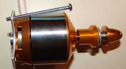
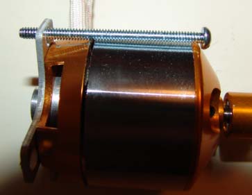
BP Hobbies 3520-6 Outrunner Brushless Motor
By Ken Myers
This TowerPro (www.towerpro.cn) Chinese Brushless Outrunner is available from BP Hobbies (www.bphobbies.com) for $52.95.
Weights:
Measured motor weight w/leads: 9.27 oz./262.8g
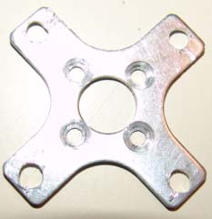
Aluminum motor mount: 0.18 oz./5.1g
4 mount screws: 0.07 oz./2.1g
Prop adapter: 0.78 oz./22.2g
3 Anderson Power Pole connectors: 0.17 oz./4.9g
4 6-32 blind nuts: 0.14 oz./4.1g
4 2" 6-32 screws: 0.42 oz./11.9g
4 1" nylon spacers: 0.08 oz./2.4g
APC 10x7E thin electric prop: 0.67oz./19g
Total weight: 10.98 oz./311.3g
It should be noted that the manufacturer, TowerPro, and most of the distributors, including BP Hobbies, list the weight as 237g. Steve Neu, in his December 2006 Quiet Flyer Power On column gave a weight of 268g. My weights show the weights of the various components and the APC 10x7E prop. It is a tad heavier when using the APC 11x8.5E prop.
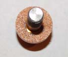
Before running the motor/prop tests, sandpaper was glued onto the prop adapter to help the prop grip the adapter when tightening the prop nut.
The aluminum "X" motor mount, provided with the motor, is too "short" and the holes for mounting the motor are too close to the motor body to allow the screws to pass through them in a straight line.
I fixed this minor annoyance by elongating the holes in the mount.
An interesting thing happened when testing the Jeti Spin 44 and this motor. It was written up in the December 2006 Ampeer with the title "Mathematical Motor Modeling, Again" and involves the differences I accidentally discovered while doing bench tests of this motor.
Motor/Battery/Prop Data:
Data: (Elevation: Walled Lake, MI 938 ft./286m, Ambient Temperature: ~63F/17.2C, Barometric Pressure: 30.36 in./1017.3 steady, Humidity: 78%)
Generator Test: Mfg. Avg. Kv from generator test: 737
RPM: 1560 Volts AC RMS: 1.577 * 1.414 vpk = (2.229878 * (1000/RPM) 0.641025641) = a. 1.429409
Kv= 1/a. 0.699589843 * 1000 = 699.5878 / 0.95 = 736.4
RPM: 1560 Volts AC RMS: 1.581 * 1.414 vpk = 2.235534 * (1000/RPM) 0.6410256 = b. 1.4330346
Kv= 1/b. 0.6978198 * 1000 = 697.81985 / 0.95 = 734.5
RPM: 1560 Volts AC RMS: 1.568 * 1.414 vpk = 2.217152 * (1000/RPM) 0.6410256 = c. 1.4212513
Kv= 1/a. 0.7036053 * 1000 = 703.60535 / 0.95 = 740.6
Speed Control: Jeti Model Spin 44 with 24-degrees timing advance (default)
Average Data using Hyperion Emeter:
Battery: Skyshark 4S1P 4000mAh Li-Po1
APC 11x8.5E, 13.09v, 32.376 amps. RPM 8514, Watts In 424, Pitch Speed 68.5 mph/110Kmph
APC 12x6E, 13.484v, 30.794 amps, RPM 8934, Watts In 415, Pitch Speed 50.8 mph/82Kmph
APC 11x7E, 13.296v, 28.688 amps, RPM 8798, Watts In 381, Pitch Speed 58.3 mph/94Kmph
APC 10x7E, 13.496v, 24.252 amps, RPM 9174, Watts In 327, Pitch Speed 60.8 mph/98Kmph
Battery: True RC 5S1P 4000mAh Li-Po
APC 10x7E, 17.028v, 38.748 amps, RPM 11280, Watts In 660, Pitch Speed 74.8 mph/120Kmph
1. Readings were taken on the same fully charged battery in the order of 12x6E, 11x8.5E, 11x7E, and 10x7E.
Wanting to see how the ESC timing affects the motor, I set the timing to 0-degrees using the Spin Box and took the following readings on a freshly charged batteries:
Average Data using Hyperion Emeter:
Battery: Skyshark 4S1P 4000mAh Li-Po1
APC 11x8.5E, 13.304v, 31.37 amps, RPM 8472, Watts In 417, Pitch Speed 68.2 mph/110Kmph
APC 12x6E, 13.618v, 29.154 amps, RPM 8772, Watts In 397, Pitch Speed 49.8 mph/81Kmph
APC 10x7E, 14.016v, 23.554 amps, RPM 9264, Watts In 330, Pitch Speed 61.4 mph/99Kmph
1. Readings were taken on the same fully charged battery in the order of 11x8.5E, 12x6E, 11x7E, 10x7E
Battery: True RC 5S1P 4000mAh Li-Po
APC 10x7E, 17.358v, 35.49 amps, RPM 11100, Watts In 616, Pitch Speed 73.6 mph/118Kmph
This relatively inexpensive outrunner performs as expected, is reasonably efficient and is a pretty good value. The "X" mount needs a major revision to allow the motor mount screws to fit properly. It is basically the same motor as the TowerPro 3520-7 in my Ryan STA. BP Hobbies does actually sell the -7 version for those wishing to use this motor with a larger prop or more cells.
Return to "What's In This Issue"
How to Subscribe to John Worth's RC Micro World (Webzine)
John Worth, Executive Editor
E-mail to: johnworth@cox.net
Bob Aberle sent along the following information. KM
The latest issue in on display for viewing by 2006 (now 2007 KM) subscribers, who need only go to www.cloud9rc.com and Log In with their e-mail address and password. A look at the Current Issue section of the Welcome pages shows all the subjects for this month. Each article can be looked at individually, or by clicking on Read Full Article at the end of any article listed and then clicking on Download Entire Issue, the whole month of can be reviewed in one continuous scrolling.
Note: 2005 (now 2006 KM) subscribers can also Log In the same way but only the 2005 (now 2006 KM) issues will be available, by clicking on Previous Issues at the top of the Welcome page. Exception: by going to Previous Issues, 2005 (now 2006) subscribers will be able to see the entire August 2006 issue, which may help a decision concerning renewal for 2006 (now 2007 KM), at a discount rate shown by clicking on the Subscribe box.
Payment may be made by Pay Pal, or by check, cash or money order.
Note: 2006 subscriptions are for all 2006 and prior monthly issues - they do not extend into 2007. But 2006 subscriptions provide access to all 2005 issues in addition to those produced in 2006.
Return to "What's In This Issue"
Lil Eaglet-II Update
From Bob Aberlebaberle@optonline.net
I thank you for mentioning my two "little birds". (In the December 2006 issue. KM) The LIL EAGLET-II, with the inverted "V" tail took a little re-doing. But now it flies just great!
The problem was the flat, no airfoil, sheet balsa wing. At Tom's suggestion, I replaced that wing with one using a Jedelsky section. I hadn't used an airfoil like that since my old FAI towline model days. It is simple to construct and as it turned out made all the difference in the world in flight performance.
Attached are a few final photos, one with Tom launching a flight. It still appear in the January 2007 RC MICRO WORLD. (see above info about RC Micro World KM)
On another point, I was trying my "How High" altimeter along with its companion, "SEE HOW" device that reads the peak altitude, without having to count flashing LED's. I resurrected my ten-year-old PLAYBOY, SR (630 sq.in.) that I had won first place in Class-B Old Timer at the 1996 E-NATS. The plane has an old Astro geared FAI Cobalt 05 using an Aeronaut (white) 12.5x6 folding prop. For Class-A (60 second motor run time) I used a 7 cell Sanyo 1250 NiCd pack (11 ounces) and for Class-B (45 second motor run) an 8 cell 1250 pack (13 ounces). The plane weighs something like 44 ounces.
Well, for test flights last Monday, I substituted my three-cell A123 2300 pack (9 ounces). This set up must draw about 40 amps, which would be a 17C load. To my surprise the PLAYBOY never flew as well. I put it almost out of sight in less than 45 seconds. With no thermals, early in the morning, I still got 10-minute flights. The recorded altitude on landing was around 1100 feet. I was able to obtain four essentially identical flights on the one charge! With the old Ni-CD packs I had to recharge after every flight!
The bottom line here is that our NEAC/E-NATS might be totally revitalized using these new A123 batteries. I'm going to mention this experience to Ric Vaughn.
 Return to "What's In This Issue"
Coming Next Month:
Review of the Sportsman Aviation Sonic 500 from Hobby People
Have a Wonderful New Year!
Return to "What's In This Issue"
| 
