|
Flying High With Electric Power!
The Ampeer ON-LINE!
Fly the Future - Fly Electric! |
|---|
Site Table of Contents
| President: | Vice-President: | Secretary-Treasurer: |
| Ken Myers | Richard Utkan | Rick Sawicki |
| 1911 Bradshaw Ct. | 240 Cabinet | 5089 Ledgewood Ct. W. |
| Commerce Twp., MI 48390 | Milford, MI 48381 | Commerce Twp., MI 48382 |
| (248) 669-8124 | (248) 685-1705 | (248) 685-7056 |
 | ||
| Board of Directors: | Board of Directors: | Ampeer Editor |
| David Stacer | Arthur Deane | Ken Myers |
| 16575 Brookland Blvd. | 21690 Bedford Dr. | 1911 Bradshaw Ct. |
| Northville, MI 48167 | Northville, MI 48167 | Commerce Twp., MI 48390 |
| (248) 924-2324 | (248) 348-2058 | (248) 669-8124 |
| Mailed Ampeer printed subscriptions are no longer available.
The Ampeer is FREE on-line in Acrobat .pdf format and HTML with active links! | ||
| The Next Meeting:
Date: Thursday, Jan. 16 Time: 7:30 p.m.
Place: Ken Myers' house | ||
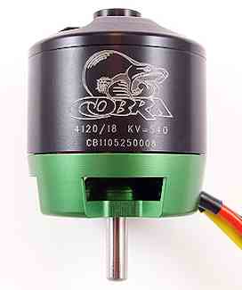
| Cobra C-4120-18 540Kv Outrunner Tested, Ken Myers presents the data he collected while bench testing the Cobra C-4120-18 540Kv outrunner. | The Servo Conundrum Continued Ken Myers continues his research into selecting the appropriate servo(s) for a given RC model airplane. |
| Comments Regarding the December 2013 Article, "Servos, I Don't Know Jack" Ampeer readers share their thoughts on this article and provide some information. | A Better Way to Set Up the Throttle Cut Feature on the Tactic TTX650 to be Used as a Throttle Lock Roger Wilfong provides information on a better way of setting up a throttle lock on this transmitter. |
| Time Flies Joe Hass shares a "growing up" composite photo of Chris Hass. | Mark Freeland Receives the Carl Goldberg Vital People Award Information on Mark and his 2013 Carl Goldberg Vital People Award. |
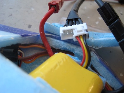
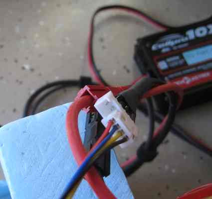
| A Balance Cable for a CellPro 10XP David Stacer, EFO member, explains how he made a very useful cable for charging A123 in the plane without having to 'mess' with an adapter board. | Eneloop Tests Keith Shaw evaluates the self-discharge characteristics of these LSD NiMH cells and finds them very useful as receiver and transmitter packs. |
By Ken Myers
The Back Story Long time flying buddy, Ken Johnson, decided that he would like to try electric power. He has flown internal combustion glow and gasoline powered planes for over 30 years. He had built a Concept Fleet biplane decades ago and decided that he'd like to convert it to electric power from glow. After the conversion it should weigh about 6 lb. ready to fly with a wing area of about 750 sq.in. I'd recently been doing some 'motor research' for an article, and I'd remembered the specifications for the Cobra C-4120-18 540Kv motor. It is supplied by Innov8tive Designs. There is an active thread on RC Groups with more information about Cobra motors. "Lucien Miller has these motors produced for him by Danlions in China. Danlions makes Pulso motors. The differences between Lucien's specifications and the 'standard' Pulso motors are noted in the same thread on RC Groups. I have several of the Scorpion line of motors, which are also supplied by Innov8tive designs. I have been very pleased with my Scorpion motors and have recommended them to many of my flying buddies. Ken and I decided it was time to take a serious look at the Cobra motors. Lucien Miller is known for providing the best motor, voltage and prop data in the business. I value his dedication and hard work in this area. How he collects this data is explained on RC Groups. Since I had previously researched this motor, I had already entered the Innov8tive Designs propeller, amperage and voltage data into Drive Calculator. Ken's Fleet biplane can safely clear up to a 14-inch diameter prop. Based on the preliminary Drive Calculator predictions, I had him purchase APC 13x8E, 13x10E and 14x8.5E props. Ken brought the power system over for testing on the morning of October 21, 2013. We noted that, externally, it is a nicely finished motor. We could see the windings on the stator, and they also looked to be well done. The only disappointment was that the set screw for the shaft collar would not thread into the shaft collar. We replaced it with a different shaft collar. The component weights were gathered in grams using a scientific triple-beam balance scale and the dimensions were measured. All of the weights and measures were within reasonable tolerances compared to the data posted on the Innov8tive Designs Web page for this motor. Innov8tive Designs gave the motor weight as 290g and this one weighed 291.4g or 10.28 oz. With the "+" mount and prop adapter added it weighed 324.9g or 11.461 oz. The motor was 'drill press' tested for Kv. A 6S "A123" 2500mAh pack was charged and then the motor data collected, volts, amps, and RPM, using the Emeter II for two no load runs and then, in this order, APC 12x6E, 13x6.5E, 13x10E, 14x7E and 14x8.5E props. The elevation and atmospheric conditions of the test were; elevation ~287m, temperature ~60-deg F/15.6-deg C, pressure 29.85 inches and steady. Lucien noted the Io as 1.5 amps @ 20V. The Emeter II captured 2.32 amps @ 20.01V. This indicated that our motor was going to produce data somewhat differently from the one Lucien tested. The calculated Kv, using the drill press method, was 528. That is somewhat lower than the stated 540. After inputing the captured data into Drive Calculator, it calculated a Kv of 516. Again this indicated that our numbers were not going to be the same as those posted on the Innov8tive Design Web site. Here is a link to the spreadsheet with the gathered data. The pack was recharged and the APC 13x10E prop affixed to get the number everyone likes to share, the watts in. After running off the top charge of the 6S "A123" 2500mAh pack for about 10 seconds the Emeter II captured; 17.1V, 37.9A, 7346 RPM, 647.4 watts in. That yields a pitch speed of 69.6 mph. The time and effort that Lucien Miller has put into the data on his Web site is well worth it. I was able to select the correct motor for Ken's plane on the first try, and it once again proved the value of having a reliable vendor who provides data above and beyond the others in this market! With a motor weight of 290g and 650 watts in, the watts in to motor weight ratio is 2.24:1, well below the 'mythical' 3 watts in per gram of motor weight maximum. Ken's Castle Creations' Edge 50 will only see about 40 amps at the most, which is 80% of its rated capacity. All in all, this should be a very 'happy' power system. Ken Myers After my article "Servos, I Don't Know Jack" in the December 2013 Ampeer, I continued thinking about servos. Those of us who have been in this hobby for several decades seem to know what servo to use in what application. It appears to be an acquired skill based on anecdotal information and osmosis. For well over a month I searched the Internet to see if there was a rule of thumb that applied to servo selection. In every instance a request for a formula, or rule of thumb, was answered with anecdotal information. A thread on RC Groups is typical. The thread is named, "Determining Servo Torque Required for RC Model Airplane". Please take a quick look at this thread. There really is no answer provided to the original poster's question. There are many, many, many replies similar to this all over the Internet, not just on RC Groups. In many of these threads there is also a great deal of misinformation. A thread on Watt Flyer is typical. The discussion in the Watt Flyer thread pertains to using a 1:1 ratio of torque in units of oz-in to airplane weight in ounces. Before finding that thread, I had logged data for over 100 prop driven model aircraft from the 2006 and one 2007 Fly RC magazine. The logged data included planes powered by electric motors, glow motors and gas motors. I grouped the planes into 3D, glider, scale, sport and (flying) wing. The data is available on the spreadsheet servo-data.xls under the tab 'raw data'. Fly RC magazine was used to gather much of the data because I physically had the magazines. Back then it was a good magazine with data provided in the reviews that could be used to calculate pitch speed. From my earlier research, it appeared that aircraft 'speed' was a somewhat important factor in determining the required servo torque. (see "Servos, I Don't Know Jack!" in the December 2013 Ampeer) I spent weeks trying to find some kind of rule of thumb/formula for selecting servos based on 'pitch speed', relationships of weight in ounces and pitch speed and other possible variations. I used a tab on the same spreadsheet called 'working' to try out various formulas. It was very frustrating and nothing seemed to work. Many of the 'dead ends' were deleted, but I left one 'dead end' at the top of the sheet named 'working'. After so very many 'dead ends', I began to believe that for a simple rule of thumb, that certainly does not apply to all situations, aircraft weight in ounces was the most reasonable way to go, if a rule of thumb could even be derived. When I saw the 1:1 statement perviously noted, I thought that it couldn't be correct. The collected data indicated otherwise. I created a sheet in the spreadsheet workbook named raw data +. The plus was added to indicate that I had now switched to only looking at the type of plane and the weight ratio between the plane and the servo torque at 4.8V expressed as a percentage. More plane and servo data was also added. I looked at the 40 planes defined as 3D. Eight were found where the relationship of the torque in oz-in to the aircraft weight in ounces seemed excessive. The excluded aircraft were, for the most part, small, light planes where it was 'obvious' that servos with less torque could have been used. This is purely anecdotal on my part. That left 32 instances in the data. The servo torque divided by weight ranged from 34% of the planes weight in ounces to 105%. The average of the 32 instances was 64% and the median 59%. Examples of the average and median: Avg.: Carl Goldberg Extra 330, 224 oz., Hitec HS-5645MG, 143 oz-in, 64%
Ten electrically powered 'gliders' were found. The servo torque divided by weight ranged from 24% to 92%. The Average and Median torque was 56% of the RTF weight. An example to demonstrate an average and median glider:
There were 66 scale planes logged. Again I found 12 where the relationship of the torque in oz-in to the aircraft weight in ounces seemed excessive. Once again, the excluded aircraft were all basically small, light planes where it was 'obvious' that servos with less torque could have been used. There was an exception. The 141 oz. Hangar 9 Miss America P-51 ARF used JR NES 791 servos with 260 oz.-in. of torque for the servo torque being 181% of the weight. The 54 remaining aircraft where the servo torque divided by weight ranged from 14% to 103%. The average of the 54 instances was 49% and the median 45%. Examples of the average and median: Avg.: League Models Extra 330 ARF, 252 oz., JR ST125MG, 125 oz-in, 50%
I was not surprised to see the servo average and median percentages in the 3D planes higher than the scale planes. Anecdotal information has usually suggested that. There were 52 sport planes logged. I found 9 where the relationship of the torque in oz-in to the aircraft weight in ounces seemed excessive. The excluded aircraft were small, light planes except for the World Models Commander 50CC. It was again 'obvious' that servos with less torque could have been used. There was one exception. It was the Seagull Models Harmon Rocket which weighed 105 oz. and used servos rated at 125 oz-in. The 43 remaining aircraft where the servo torque divided by weight ranged from 23% to 97%. The average of the 43 instances was 59% and the median 58%. Examples of the average and median:
I WAS surprised to see that the average and median sport plane torque to weight ratio (percentage) was higher than the scale planes. There were only two flying wings logged and both showed about a 1:1 ratio of torque to weight. Jets and Electric Ducted Fans were not included in the original data gathering, as I thought 'speed' would be an important factor. Also, there was only one small EDF reported in the Fly RC issues I had available. For those interested in Jets and Ducted Fans, the spreadsheet can be expanded for that type of aircraft. Later, three Horizon Hobby EDF's were quickly found and added to the spreadsheet. The preliminary finding is that the ratio is about the same as for the scale class, which is lower than I expected, average 48% and median 45%. Remember that this is only 3 planes from a single brand. My Maxford USA Antonov An-2 weighs 98 oz. and the recommended Hitec HS-55 servos are said to provided 15.2 oz-in of torque at 4.8V. 15.2 / 98 = 0.16 16% is very near the bottom of the range for scale models. I logged all of Maxford USA's available models. While logging them I noted whether the recommended servo was used in photos in the plane's manual. Many manuals did not have photos that contained the recommended servo. The build photos contained servos other than those recommended by Maxford USA. The Maxford USA scale planes showed an average ratio/percentage somewhat lower than the other scale planes. The median was about the same for both. Maxford USA: range 13% to 89%, average 42%, median 45%. For comparison;
I then logged all of my planes for which I had easily accessible data. There were 3 scale and 13 sport types. The ElectroFlying Fusion was counted twice as it flew with 3000mAh NiMHs at a different, heavier, ready to fly weight than the "A123" 2300mAh battery I am using now. I also figured in the servos that I noted I wanted to use for the SR Batteries X-250 instead of the ones used because the ones I wanted were not available. My range is from 13% (that's the An-2) to 102%. My average is 64% and median 55%. When the three scale planes are included, then the average is 64% and median is 54%. One plane was dropped from the data, the SR Batteries Bantam, as it could have easily used servos with less torque. My average and median planes are:
I was amazed at how close my average and median planes were to the average and median logged planes; average 61% and median 60%. At a later date, data was gathered from other sources when it became apparent that speed would not be involved in the process, although it MUST be taken into consideration if the plane's speed will exceed the typical pitch speeds of 50 mph to 65 mph range for sport and advanced sport models. The expanded database is in the spreadsheet. The new data, along with the previously logged data, is on the spreadsheet titled raw data +. While gathering the new data, it became apparent that the servo choice was left up to the modeler to determine with the supplier using such phrases as; "3 mini servos", "4 micro servos", etc., quite a few times. My previous article on servos explained why this type of description is ambiguous at best. Also, many authors of reviews didn't state what servos they used in any part of their review. Adding more aircraft to the data only changed the original data slightly.
Based on the data I collected I was amazed that I was using this same data acquired in my head to select servos for my projects. As far as I am concerned, the sub-micro servos in the An-2 are still an experiment. I certainly cannot say, yet, that I would recommend them to anyone based on the data that I've collected. One last note: I found the servo torque quickly by using Google to search for the name of the servo and using a site called www.servodatabase.com to retrieve the servo torque data. From Gary Gullikson, via email I read your write-up in newsletter about choosing and setup of servos. Gotta read it again to make sure I got the part right about using dual rates vs using full throws for least strain on servos. I too was confused by Maxford's recommendations to use HS-55s on their large .40 sized Gee Bee E. I bought HS-82MGs to be safe, especially for the rudder/tailwheel steering. Haven't assembled the Gee Bee yet, just finished my glacial Sig Cub build, started over 30 years ago. Taxi-testing rained out today. Here's a link to Gary's Cub build. Hi Ken, Love the Ampeer, always a great source of information. (Thank you very much! KM) Thanks for the links you provided to the servo torque calculators. I'm working on a new plane now, and will definitely use these to help size the servos required. I recently listened to a back episode of the "All Things That Fly" podcast (#260). The major subject of the podcast is "All About Servos." An interesting metric that was put forth early on is 1 oz-in of torque for each sq.in. of control surface for a typical sport airplane. Also of interest, mentioned in the podcast, and located in the show notes, is a link to a servo database www.servodatabase.com/. (Thanks Jim, I did use that servo database a lot while researching information on both of the servo articles. KM) Some Notes from that Podcast
I listened to parts of the noted Podcast and gathered a few notes and quotes by Lucien Miller. "Go from the (plane's KM) manufacturer's recommendation." "The servo you use is dependent on the size of the aircraft and how fast it flies." "A rule of thumb that I like to use is an oz-in of servo torque per sq.in. of control surface. And this is for most standard size sport planes... Obviously if you are flying super high speed planes 300 mph you are going to need more torque in your servos." Paraphrase: Really slow planes don't need one oz-in servo torque per sq.in of surface area. The example given was a 38" span 3D foamie where 1/2 the wing area is the aileron can use much less than one oz-in servo torque per sq.in. of surface area. "Again it comes down to air speed and aircraft size as well as the control surface size." "Most of the models out there give you a recommendation on servo size. If you stick with that you are going to be good." Ken's Comments: As noted in the "Servos, I Don't Know Jack" article, the recommendations by the plane's supplier can be quite ambiguous at times. This has nothing to do with the topic or what was said by Lucien; I really dislike listening to a Podcast when compared to reading. I guess I'm just too old school and prefer the written word over the spoken word, which evaporates too quickly for my mind to absorb. From Roger Wilfong, EFO Member, via email In the November 2013 Ampeer you gave instructions for setting the Throttle Hold/Cut feature on the Tactic TTX650 transmitter. I've been doing this on my Futaba 8U(s) transmitters for some time through a user programmable mix. I began using it with "full housed" electric glider so I wouldn't accidentally start the motor while I was hunting thermals, and decided it was a good safety feature for regular sport planes. On the 8U I used the programmable mix because the built-in throttle cut feature in the 8U really only offsets the throttle by an increment in order to fully close the carburetor on an IC engine - so it really isn't usable as an "electric" throttle hold feature. It was nice to see that the Tactic has a more functional Hold/Cut preprogrammed. I'd suggest a change to one of your steps and the addition of another in setting up the TTX650 throttle cut function for electric use. I initially set up the Throttle Cut function using the using the same procedure you detail in the Ampeer article and found two problems: 1) If the Throttle Cut was engaged when I turned on the Rx and ESC, the ESC would calibrate the 0% cut value as "low throttle". This resulted in the ESC going to 10% throttle when the switch was turned off. On one ESC I tried, this resulted in the motor staying running when the throttle stick was in the low position - actually the motor began singing when I flipped the switch off, but there wasn't enough power to get the motor moving from a dead stop. 2) Unless the throttle stick is in the full down position, you can't engage the Throttle Cut function. This is the result of the "Trigger" setting in the Throttle Cut setup. I believe this is awkwardly (inadequately) described in the manual so briefly the effect of this value is that the throttle cut function will not activate if the throttle is set above the "T" trigger value - by default 10%. This is probably a safety feature directed more at the IC community than electric's since it could result in an IC engine quitting in flight. But it has some hidden problems if you are expecting the cut function to be activated whenever you flip the switch. The most obvious one is that if you have the throttle any place but full down, the function will not engage. But less obvious is that if you ever bump the throttle trim up even one notch, it becomes impossible to engage the throttle cut. While the display will still show the throttle at 10%, internally it is in fact ever so slightly higher than 10%. Fortunately, it's an easy change to eliminate these problems. The first can be fixed by simply leaving the "Cut." value at the default 10% (unless you going to adjust the lower "Travel Limit" on the throttle to greater than 100%). This should leave the throttle effectively at "0" when the switch is activated. The second can be done by setting the "Trig" to a higher value. You do this by pressing the "Down Arrow" once after selecting the control. I found the manual's instructions on setting this value a little confusing. Unlike changing the "Cut" value, you don't press "Enter" and use the arrows to adjust the value. Instead, with the cursor on the "Trig" value, move the throttle to the value you want and then press "Enter" to take the value (it took several readings and a bunch of hacking for that to sink in). You might not want to set the "Trig" at 100% as you could kill the motor at an inappropriate time - like reaching for the gear switch after takeoff and accidentally going from full throttle to dead. But you could set it for 20-30% This would avoid the lock out problem caused by the trim setting and still activate at low throttle settings. Thanks Roger, great advice! I hope most of you saw Greg Gimlick's column on this topic in the December 2013 Model Aviation. KM A Photo from Joe Hass
Joe sent along this composite photo of Chris Hass. The 2003 photo appeared on the March issue of RCM magazine. What a great young man he has become! KM On Tuesday evening, November 12, Mark Freeland was presented a Carl Goldberg Vital People Award for 2013 at a very special meeting held at the Ultimate Soccer Arenas in Pontiac, MI. The 'Vital Person' award is given to five people each year in the US for their their dedication above and beyond in support of the AMA and model aviation. As owner of Retro RC, Mark has selflessly donated his time and efforts to the advancement of the model aviation hobby. He has donated both his time and talent in bolstering and supporting model aviation education. He supports model aviation events through generous donations of his unique products. He shares his knowledge and expertise with all of modelers who ask. He is truly a "vital person". Several very special guests, besides Mark's family, were in attendance.  In the photo from left to right; Gary Weaks (Vital People Winner), Tim Jesky (AMA VP District VII), Mark Freeland, Joe Hass (submitted Mark for the award and presenter), Keith Shaw (Vital People and AMA Hall of Fame Member) and Ken Myers (Vital People and AMA Hall of Fame Member). Also in attendance was Peter Waters, another AMA Hall of Fame Member. Thanks so very much Mark for everything you do every day for this hobby!!! An interesting side note is that Keith, Ken and Peter are all members of the Midwest RC Society. From David Stacer, EFO Member, via email I field tested my new 10XP balance cable today and it worked exactly as designed. I didn't like how short the wires on standard 10XP balance board are. The balance connector wires on some of my packs are very short and it was hard to get them plugged into the charger balance board. I had some extensions on the board but I was not happy with their length either. Most of my airplanes use the A123 packs and I always charge them in the model, so the short cable was a problem. I could have purchased the 36" long cable, that is available for the CellPro charger, to extend the balance board farther away from the charger but I have come up with what I think is a better idea. The CellPro 10XP charger has two different wiring modes for the balance connector. FMA Wiring mode and XH/EH Wiring Mode. To make my new balance cable work I needed to change the mode to the XH/EH mode. Here's the link to the 10XP charger. 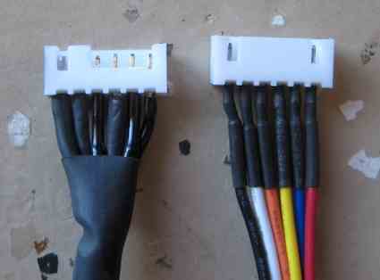 I removed part of the plastic on a 6 pin JST-XH connector. This allowed 2S, 3S, 4S and 5S packs balance adapters to be plugged into the one 6 pin/5S JST-XH connector. It still has one of the indexing slots so you can't plug the balance connector backwards. Modifying the connector was the key to making this idea work. Next I soldered the new "hacked" 6 pin XH connector to one end of a piece of stranded Cat-5 Patch cable. On the other end I soldered the JST-PA connector. This is the connector that plugs into the 10XP balance port. Now I had a balance cable that is 36" long and a single connector on the end to charge/balance all of my packs. I also made up 36" long charge cables and used Velcro straps to keep all three together. 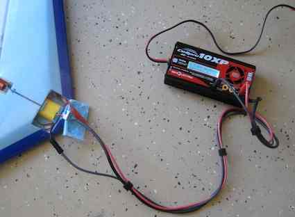
Thanks so much for this handy tip Dave. KM From Keith Shaw, via email I thought you might be interested in the self-discharge tests I have recorded on my six Sanyo Eneloop battery packs. These are all the small AAA-size 700 mAh receiver packs I've been using to replace my aging nicads. Still collecting data on the AA-sized 2000 mAh cells I'm now using in all my transmitters. These cells are NiMH chemistry with a breakthrough separator design that gives them self-discharge rates similar to LiPo cells. This is great for those planes I fly only occasionally, as there is now enough charge left to get a couple of flights on them when the weather or whim arises. This has been a boon to my sport flying, as I would always find the plane's receiver pack too low, or even dead when I wanted to fly it. BTW, I do NOT use or recommend BEC in any plane you really care about. A motor/controller/BEC blow up usually means the loss of the plane in the resulting radio-dead crash. With a separate receiver battery the plane can safely glide back to a landing. I only use BEC in very small planes. I bought a bunch of individual cells and did a lot of performance tests before switching over to them. I have been endlessly disappointed with all the previous NiMH "wonder cells" that the press has touted over the years. I found short cycle life, horrid self-discharge, and quickly dropping capacity that would always send me back to my reliable nicads. It really seems that Sanyo has solved all the problems with their Eneloop series. I purchased most of the packs and individual cells from Dave at Radical RC, but I have found the cells available at some of the Batteries Plus stores, and even a few chain retailers. I keep a log of flights and charge cycles on all my planes, so this data is collected from the logs. Recently I went on a month long driving vacation, so all the packs had at least a one month dormancy. Some packs hadn't been charged for almost four months, so I had a nice data spread over the 1-4 month period. The bottom line is that the results fell on a nice straight line with a slope of 10%/month. This means that if the 700 mAh pack had been dormant for two months, the remaining charge would be 80%, or 560 mAh. In fact, that particular pack discharge tested to 554 mAh. If the pack had been sitting for 4 months, there still would be 60 % charge (~400 mAh), easily enough for a couple of flights. A few other notes on these cells. The good news is that they have a lower impedance than the typical 600-700 mAh Sanyo nicads I have always favored, so there is less voltage sag when a lot of servos are moving. The little AAA 700 mAh pack is tiny and weighs barely 1.5 oz, so it fits in all but the smallest planes. The classic slow charger provided with every radio is a perfect match for them, so the conversion to Eneloops is simple and painless. The bad news is they really don't like fast charging, even a C/3 rate degraded the self-discharge characteristic of one of the test cells. They also don't like to be over-charged at the usual C/10 rate. ĘIf I want to charge one of these packs, I try to estimate its current charge state with an ESV, like 1/2 or 3/4 capacity. Then I recharge it with my standard C/10 charger to fill that and a little more. ĘAs an example, say the pack is about 1/2 charged, so I need to add 1/2 x 700mAh =350mAh. If the slow charger from my radio puts out 60 ma, it would add that much in 350/60, or about 6 hours. To give a bit of a edge, I will charge the pack for 7 or 8 hours. But not the usually 20-24 hours like we're used to doing with nicads. I'm very happy with these cells. The 2000 mAh AA cells seem to be even better at delivering current and holding their charge. I think I have charged each of my transmitters only twice this year. I did make up a 150ma charger for the AA packs to better-match their charging needs. Back to prepping a few planes to enjoy every minute this glorious fall flying weather. Building season will be here soon enough. Keith To Reach Ken Myers, you can land mail to the address at the top of the page. My E-mail address is: KMyersEFO@theampeer.org |