|
Flying High With Electric Power!
The Ampeer ON-LINE!
Fly the Future - Fly Electric! |
|---|
Site Table of Contents
| President: | Vice-President: | Secretary-Treasurer: |
| Ken Myers | Richard Utkan | Rick Sawicki |
| 1911 Bradshaw Ct. | 240 Cabinet | 5089 Ledgewood Ct. W. |
| Commerce Twp., MI 48390 | Milford, MI 48381 | Commerce Twp., MI 48382 |
| (248) 669-8124 | (248) 685-1705 | (2480 685-7056 |
 | ||
| Board of Directors: | Board of Directors: | Ampeer Editor |
| David Stacer | Arthur Deane | Ken Myers |
| 16575 Brooklane Blvd. | 21690 Bedford Dr. | 1911 Bradshaw Ct. |
| Northville, MI 48168 | Northville, MI 48167 | Commerce Twp., MI 48390 |
| (248) 924-2324 | (248) 348-2058 | (248) 669-8124 |
| The Next EFO Meeting: Date: Wednesday, Jan. 11 Time: 7:30 p.m.
Place: Ken Myers' house | ||
| Looking Back in Time Ken discusses the Complete Ampeer Index and how he just added 1993 to the Ampeers available online. | Does This Mean We Won? A pictorial editorial by Ken Myers. |
| My Revolextrix Gt500 Follow-up Ken Myers does a follow-up to his review on the Revolectrix Gt500 Charger. | The November EFO Flying Meeting Photos and information from the flying meeting on November 6, 2016. |
| A Pedestal Tail Solution Keith Shaw shares how he solved the problem of a raised horizontal stabilizer. | Another Sticky Building Issue Solved on the Sparrow Jet Keith Shaw describes how he engineered the wing spar to allow the ducted fans to pass through them and still be strong. |
| Finishing Up the Sparrow Jet Framework Keith Shaw shares some of the airframe finish work. | More Sparrow Jet Finish Work Keith Shaw continues with more finish work on the Sparrow Jet. |
| Wayne Giles ESR Meter Availability Ken discusses the availability of this meter and where to purchase one. | |
By Ken Myers I'm not sure how many Ampeer readers use The Complete Ampeer Index. If you have looked at the index, you may have noticed that some of the early years are 'missing'. The first issues of the Ampeer were produced on an Apple II and then an Apple IIGS. The masters were printed with a dot matrix printer and taken to a copy shop to produce the copies that were mailed all around the world. The early Ampeers contain a lot of information on the growth and direction of electric flight. If you can pull yourself away from Facebook for a while, you might find some interesting, and even still useful, information in the index. I bring this up because, in the middle of November, I spent a full 3.5 days scanning and indexing the 13 1993 issues. I was even surprised at what I found there. The first surprise was that there were 13 issues. There was so much to share in January 1993 that there were actually two issues sent out, the regular and the Extra. Some of the highlights of 1993 include the Keith Shaw Talk to the EMFSO (Electric Model Flyers of Southern Ontario), discussions of battery types, including LiPo batteries, construction articles for a peak charger and high rate speed control, a construction article for Martin Irvine's Krumpette with full-size plans for geared Speed 400 power and 6 or 7 cells, the Sport Fliers Association vs the AMA, problems with the FCC over our frequency use, many reviews and articles regarding the Sanyo 1700SCRC cells, crosswind landing techniques, Aveox brushless motors, controllers and how they work, large AstroFlight cobalt motors and large electric planes, computer power system selection programs (including mine), high rate ESCs from JOMAR, Hardy Benson, Lofty Pursuits (Doug Ingraham), flying at high altitudes, info on twins, bonding skins to foam wing cores, ducted fan info, early electric fly-in reports (including the Mid-Am), several articles by Leon H. Rasley written from a novice point of view, electric kit reviews, silking and doping techniques, everything you wanted to know about Ni-Cads, how hard it is to get converts to electric, humorus articles written tongue-in-check, how to make decals, early electric fly-in notices (lots of them!), what happened at the EFO meetings through the year, and much, much more. If you are fairly new to electric flight, you should find the older Ampeers full of interesting insights and the history of where 'we' came from. If you are an 'old hand' at electric flight you will run across names, places, planes, products and ideas you may have forgotten about. They really provide a wonderful walk down memory lane. Enjoy 'em Does This Mean We Won?
Return to "What's In This Issue" My Revolextrix Gt500 Follow-up
I reviewed the Revolectrix Gt500 in the May 2016 issue of the Ampeer. I did a short follow-up in the July 2016 Ampeer, after using it for awhile. Since I've had my Revolectrix Gt500 charger for about a year now, and used it all through the 2016 flying season, it is still the charger for me. It is simple, extremely simple, to use. The LCD screen shows all the values that I am interested in with a twist of the scroll wheel. The set up for the different chemestries is extremely simple. For me, simple is best. It is powerful enough to do all the cells I own very quickly from a 12V marine/RV battery source. I have had a few 'issues' with it though. The reported resultant ohmic resistance (ROR) values get very 'odd' when charging comparatively low ROR cell values of some 3S 1000mAh packs. At charge termination, one cell will be displayed with a ROR value of about 1/2 the value of the other two cells. I've been in contact with Fong, at Revolectrix, about this issue, and David Gray of Progressive RC. This doesn't happen with average or poor packs, with medium to high ROR values, only the two packs with the lowest cell ROR values. All of my packs are 3S 1000mAh of various brands and manufacturer's C-rate. This phenomena has been the same since I got the charger. Neither Fong nor Mr. Gray can reproduce it and said they've never seen it before. The reporting error, for MY unit, makes me not want to trust the ROR values. The good news is that only the highest individual cell ROR value is necessary to check a pack's health over time. Another 'problem' turned out to be the FMA Alligator Clip to EC5 Cable. From the very beginning, the cable had a problem. The EC5 connectors didn't want to join together firmly. I thought that this was what was making the charger not connect to my 12V marine/RV battery. I'd reconnect the EC5 connectors, and then it would work. I fiddled with this all year. It was a pain, but I could always get it to work. On Sunday, Nov. 6, I wanted to charge a 4S A123 2300mAh pack at the flying field. I fiddled, fiddled and fiddled and then fiddled some more with the EC5 connectors to get the charger connected. I put it on my 'gotta fix it' sometime soon list. I needed to use the charger on Nov. 10. The connections gave me a problem again. I used tongue and groove pliers to seat the EC5 connectors. The charger would still not boot. I accidentally bumped a wire and bingo, the charger came on. As I continued to wiggle the wire on the Alligator Clip near the EC5 connector cable, the charger would turn on and off. Ah, bad connection. I exchanged the EC5 connectors for Anderson Power Pole (APP) connectors and have not had a problem since then. 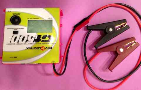 When I ran into the ROR 'oddity', I started to research the iCharger line, specifically the 206B and 306B, because they can report cell ROR values without having to have the charger in charging mode. The iChargers have received very positive reviews. After reading about them, and watching some review videos, I decided that it was not the charger for me. I'm lazy, and there is just too much button pushing for me. I believed that reporting the individual cell ROR values, while charging, would not yield consistent results during the heating process of the charge. I believed that the changing cell ROE values, shown on the display screen, were do to the heating of the cells during the charge. Cell ROR values are extremely temperature dependent. I found out that, under certain conditions, the pack and its cells do not heat up during the charging of a 3S 1000mAh pack. The pack actually cools down during charging. Please note the qualifier, "certain conditions". During some recent testing in my house, the ambient temperature was 200C. I did a series of four tests using a Dinogy Graphene 3S 1000mAh 70C LiPo pack. The pack temperature actually dropped during a charge at 1 amp, which is a 1C rate. Before each charge, the pack was heat soaked for two hours to about 220C. I have a way to do that. The results surprised me. Test 1: start temp. 22.20C end of charge temp. 19.60C
This pack's highest ROR cell, the middle cell, had a ROR of about 13.5mOhm, fully charged, at 22.00C, according the Giles meter I decided to see if this observed cooling, at a 1C charge rate, also held true for cells with a higher ROR. I believed that it would NOT. I believed that the pack would actually heat up under charge. I chose a known bad 3S 1000mAh pack. It had a cell with an ROR of 24mOhms according to the Giles meter when fully charged and at 220C. I couldn't use my worst cell ROR value pack because I had recently killed it! See the December 2016 Ampeer. As in the previous testing for the Dinogy pack, the procedure was a two hour heat soak to 220C. Charge at 1 amp. Take meter readings immediately after the charge. Take meter readings two hours after the charge, when the pack had again been heat soaked to 220C for two hours. Again, the temperature results surprised me.
While the temperature difference was not as great, it definitely went down during the charge in the 200C ambient temperature of my house. While this observed, and recorded, phenomenon seems to hold true for these realatively low capacity 1000mAh cells, I am not sure if it also happens with larger capacity cells. Using the highest individual cell ROR value during the charge is not a problem for me with this charger. Do I still recommend this charger? The simple answer is, "yes". The November EFO Flying Meeting
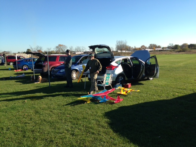
The afternoon of Sunday, November 6, was a perfect day for flying. The air temperature had reached almost 700F by 1:30. The winds were almost calm and the sun was shining brightly. The turn out was good, considering that it was the first ever afternoon EFO flying meeting, and that it followed the Midwest RC Society Swap Shop. 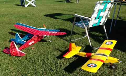 As usual, Al Straub had some really interesting planes flying. I loved his Falcon Jr. (I've got to get my kit together this winter.) 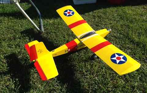
 Pete and Carolynne Foss are always a delight at the field. They can be seen at the flightline in the photo. Randy observes from the table. 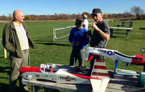 EFO VP Richard Utkan points out something to Pete Foss, while Randy looks on. Dave Stacer can be seen flying in the background. We were all grateful for this wonderful, bonus, flying day here in southeastern Michigan. A Pedestal Tail Solution
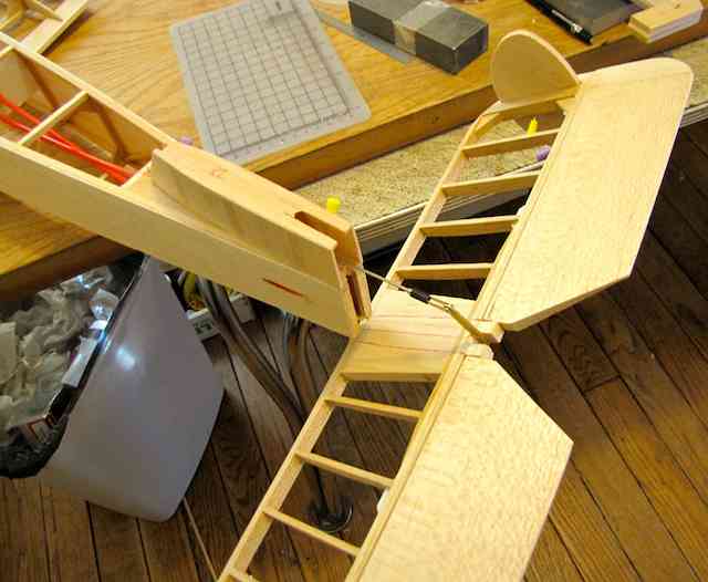
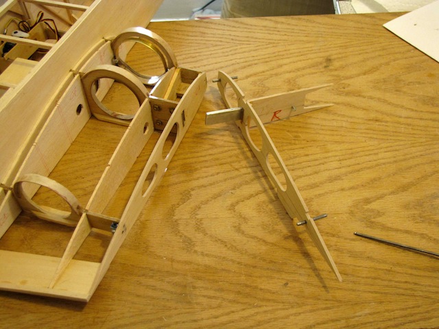
In February of 2015, Keith Shaw was working on his conventional landing gear Sparrow Jet. The full size design has a pedestal tail. A pedestal design is when the horizontal stabilizer is above the fuselage and located in the vertical fin. Obviously, he worked it out since the plane has flown for two seasons now. 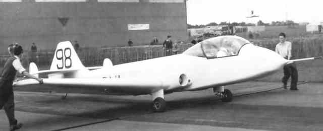 The photo of the full scale shows the pedestal tail design. And now from Keith: "I solved the pedestal tail by making the fin in two pieces that sleeve together to capture the stab. The base piece has three structural 1/4 balsa "spars". 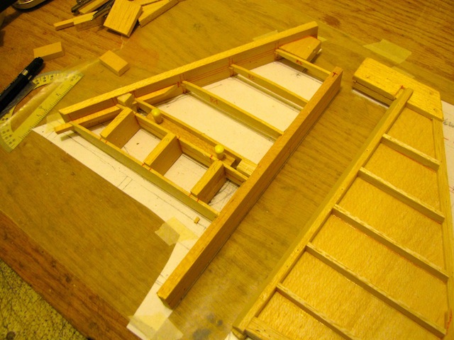
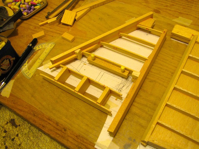
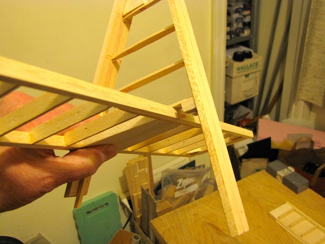 BTW, I build my tails using a constant height 1/4" leading edge and trailing edge pieces that all the ribs key into. These stay in place all the way through the sheeting so that everything stays straight. Since they are symmetrical, either side can be pinned down during sheeting. At the end, the extra material is carved away. 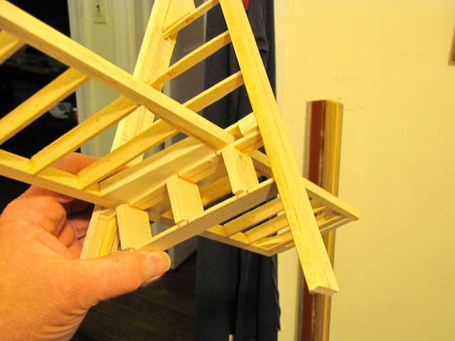
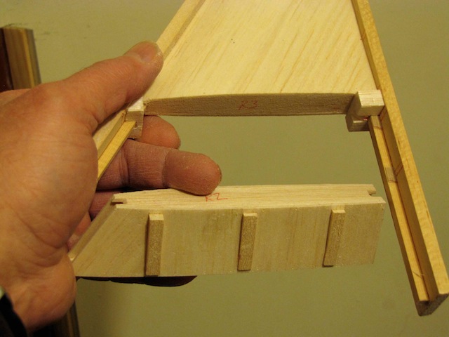
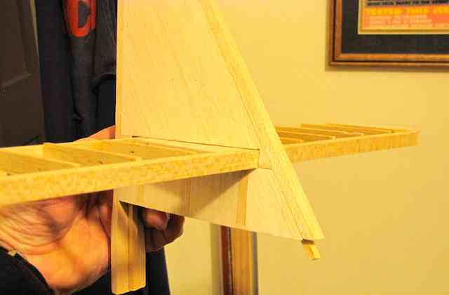 The tail assembly sequence is shown in the next five photos. The pushrods are 1/16" wire running in nylon tubes." 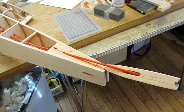
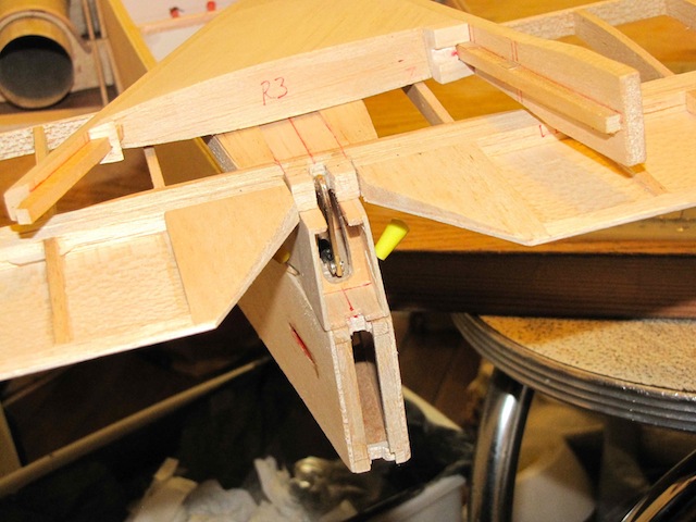
 I thought you might enjoy these insights into a master-builder's thought processes. KM Another Sticky Building Issue Solved on the Sparrow Jet
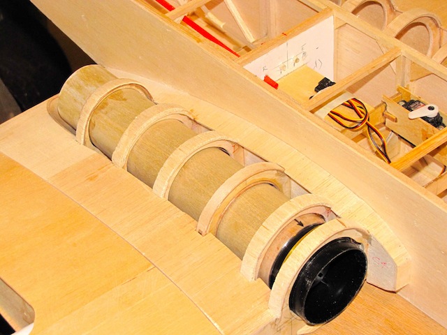
After solving the pedestal tail issue, Keith Shaw moved onto the wing spar issue. Onto the really hard engineering, the center wing spar nightmare. The two jets are mounted inside the wing, so you end up with gaping holes in the wing spars. To solve this I laminated two sheets of 1/16" ply around a piece of 3 oz carbon cloth, then cut out the parts. The spars get three layers of 1/64 ply (3/8" wide and keyed on the ends) laminated to the top, two layers of 1/64" on the inside of the hole, and two pieces of 3/16 square spruce to strengthen the lower beam. Compounding the stresses, the landing gear is also out there beyond the fan mounts. 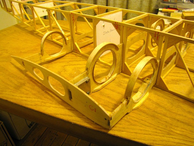
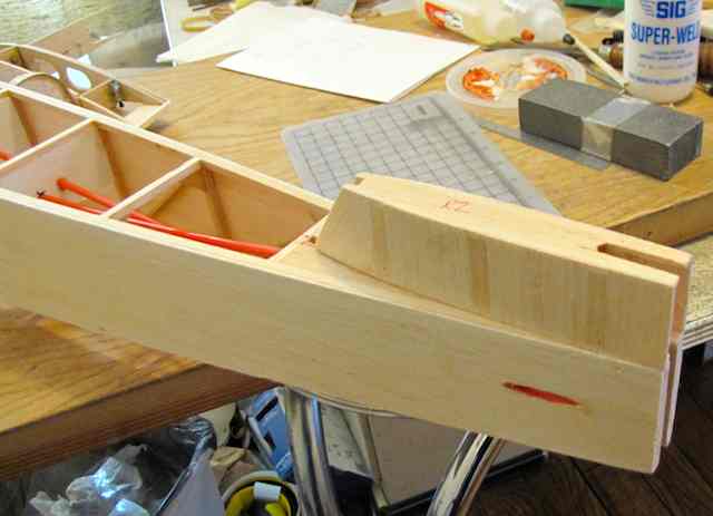
 The wing joiner actually uses the metal parts from my long departed 1992 (!) Horten IX. The root rib, metal tongue, two wire alignment pins, and spar joiner are glued together while clamped to the end rib of the center section. This assembly is then built into the wing panels to assure alignment. The front pin is passive, but the rear pin also has an locking bolt to keep the wing on in addition to the bolt on the main wing spar mount. 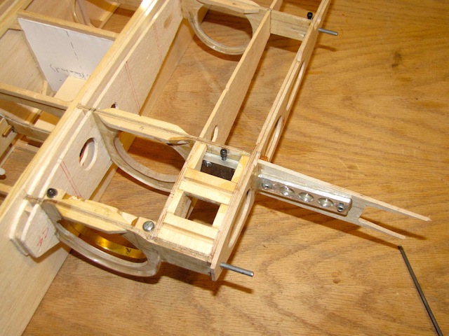
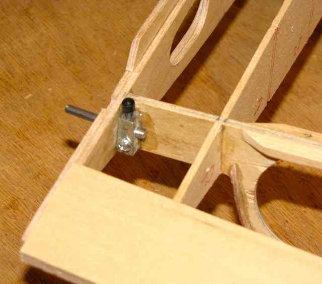 The fan units are attached to the exhaust tube (1/64 ply) with tape, and can be removed by loosening a bolt on a strap clamp and pulling them forward. The base of the front joiner has an index ridge built into it to capture and position a narrow ring molded into the EDF unit. BTW, these are the 56mm HyperFlow units like the ones in Jim Young's MiG17.
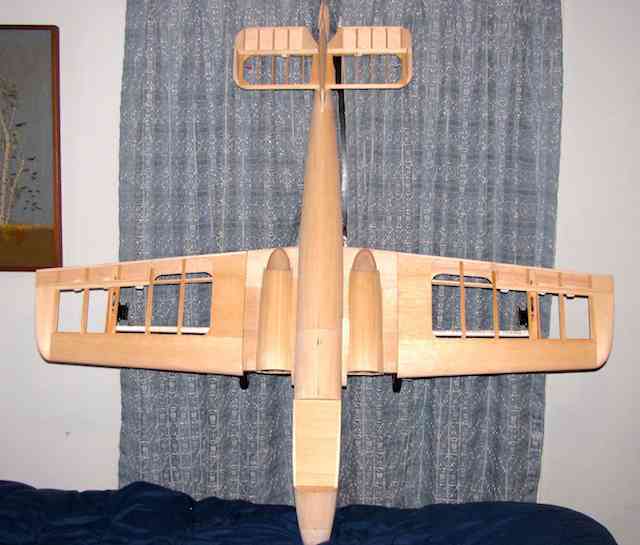
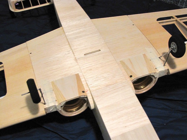
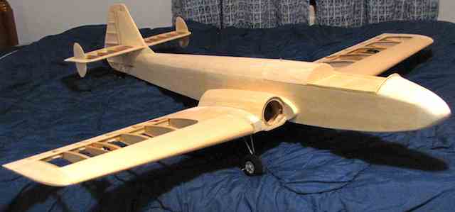
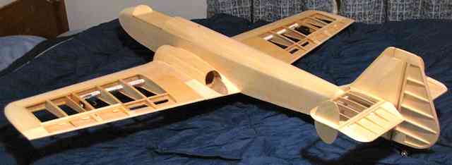
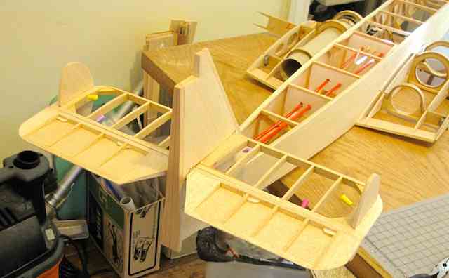
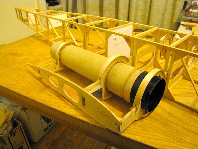 All the wood shown in the photos (fuse with center section, joiners, all tail parts and exhaust tubes) at this point weighs 19 oz. Reasonably pleased, considering a 47" long fuselage and a very complex center section and tail. The wing panels are partly done and the metal tongue and joiner piece need to be added before the top wing spar goes on. Finishing Up the Sparrow Jet Framework
The plane, as you see it, weighs 39 oz. with four servos and all linkages in place. My goal is to make it at or under 5 lb. The strip planking went better than expected. It is so important to get just the right piece of wood for the task. Wheel pants are blocked out but uncarved. I have an idea for making the front fan lip easily removable but need to do some careful drawings before cutting and carving. 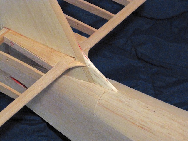
Tail Fillets
More Sparrow Jet Finish Work
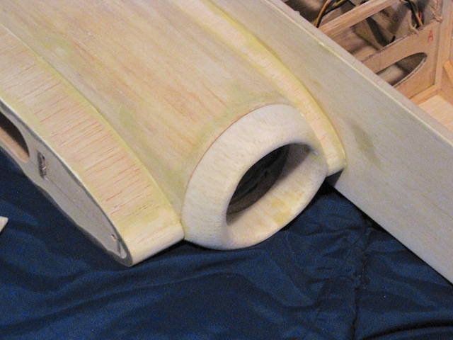
I did have to carve a canopy plug as the Sig canopy was not tall nor wide enough. The plug took a full day to carve, but the results, with the help of Jim Young's (Ken Myers') vacuum former are very good. The wheel pants were tedious to carve, but look acceptable. 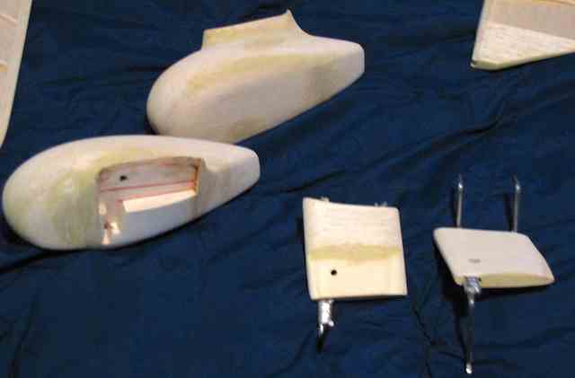 The front fan lip blocks are the most bizarre, convoluted things I have ever had to carve. I'm being driven crazy by differing grain patterns in the wood that make it nearly impossible to get the right shape. I'm on my fourth attempt, trying different wood weights and grain orientations to try to come up with a successful part. But no luck yet. And then I have to do a mirror image one. 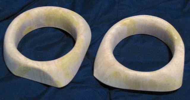
I'm seriously considering cutting off all the wood back to the front spar element and trying a completely different approach. Like using the tooling foam (used to form the canopy plug) tacked glued on theĘairframe and try to shape the whole thing rather than just the front lip.Ę Then cut it off and vacuum form the part or glass the actual foam, paint it and then mount it with some sort of flanges and screws. This would not be ideal and would make it difficult to service the fan units. 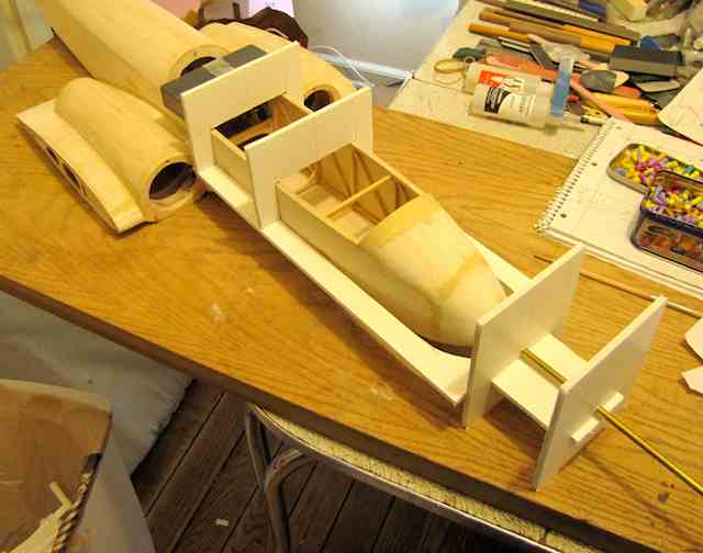 I came up with an alignment jig to drill the front hole for the pitot tube. 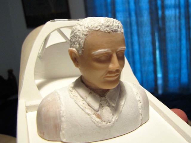 The pilot in the photos is from the King's Cup win. He is wearing a white shirt and tie and a sleeveless cardigan, no glasses, goggles, or helmet, very British. Had to do major work on the Williams Bros. head, as he parts his hair on the right, and has it brushed up in the front. The detailing is done with a combination of spot putty, modeling past and gesso. 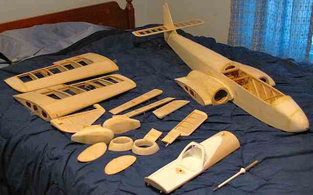 Keith Shaw's Sparrow Jet ready for finishing. To see how great this plane tuned out, check out the August 2015 Ampeer, the Mid-Am edition. Keith and his Sparrow Jet are featured about 1/2 way through the article. Wayne Giles ESR Meter Availability You may have noticed that I've been referencing the Wayne Giles ESR meter over the past year. You may have heard that Wayne is no longer producing the meter. The unit will now be produced in the USA. ESR METER - BACK IN PRODUCTION! (November 2016)
They are still available from Progressive RC. To Reach Ken Myers, you can land mail to the address at the top of the page. My E-mail address is: KMyersEFO@theampeer.org |