 |
Flying High With Electric Power!
The Ampeer ON-LINE!
Fly the Future - Fly Electric! |
|---|
Site Table of Contents
| President: | Vice-President: | Secretary/Treasurer: |
| Ken Myers | Richard Utkan | Rick Sawicki |
| 1911 Bradshaw Ct. | 240 Cabinet | 5089 Ledgewood Ct. W. |
| Commerce Twp., MI 48390 | Milford, MI 48381 | Commerce Twp., MI 48382 |
| (248) 669-8124 | (248) 685-1705 | 248.685.7056 |
 | ||
| Board of Directors: | Board of Directors: | Ampeer Editor |
| David Stacer | Arthur Deane | Ken Myers |
| 16575 Brookland Blvd. | 21690 Bedford Dr. | 1911 Bradshaw Ct. |
| Northville, MI 48167 | Northville, MI 48167 | Commerce Twp., MI 48390 |
| 248.924.2324 | 248.348.2058 | 248.669.8124 |
| Mailed Ampeer printed subscriptions are no longer available.
The Ampeer is FREE on-line in Acrobat .pdf format and HTML with active links! | ||
| The Next the Mid-Am:
Date: Sat. & Sun., July 12 & 13 Time: 10 a.m. Place: Midwest RC Society 7 Mi. Rd. Flying Field | ||
| Hitec (Multiplex) Weekender Extra 300S ARF Review Complete Review of this P2GO Extra stand off scale ARF by Ken Myers. | 12 Volt Power Supply, How To from Nick Bisonni via emal. |
| Upcoming 30th Annual Mid-America Electric Flies 2014, links to the Flyer and map and hotel info for the 2014 Mid-Am. | |
By Ken Myers After practicing 4-point rolls, slow rolls and rolling circles on the aerofly RC 7 RC flight simulator for several months, I decided that I wanted a plane that could most likely do those maneuvers better than any of my sport' planes. Researching several possible choices, and after seeing the videos of the Weekender Extra on YouTube, by 2BrothersHobby, I decided that I would give it a try. The YouTube videos are linked from the Hitec Extra 300S page. With the extremely high praise from 2BrotherHobby, I was sure this was a winner. "Before I pulled the trigger on it, I had also read several threads on RC Groups.
I downloaded the manual from the Hitec site and read through it. I also downloaded the Multiplex manual from the their site in Germany. (Update: 07/11/2017 The manual is no longer available at the Multiplex Web site. It is archived here.) The first thing I found 'interesting' in the Hitec manual was a statement on page 3. "The Weekender Extra 300S is a radio control model plane designed for novice pilots over the age of 14." The box also states, "User Lever: 3 (Novice)". Really? When the Features section is chosen on the Hitec Extra 300S product page it notes; Target User: Intermediate. That's better, but too late for someone who may have purchased the plane before researching it. Specifications from the Hitec site:
Included Equipment from Hitec manual
Battery: 3~4S 11.1~14.4V, 2200~2500mAh LiPo (The Multiplex manual only notes a 4S 2600mAh LiPo KM) Multiplex page in Germany.
Unfortunately, the specifications leave a lot of questions. What is the real motor Kv? That is important to me because I use LiFePo4 "A123" cells. What is the ready-to-fly weight? It cannot be ONLY 3.1 lb. or 49.6 ounces as the 3S and 4S LiPo packs would have different weights. In the 2BrothersHobby video they noted that they used a 179g Thunder Power 3S 2250mAh pack and a Thunder Power 284g 4S 2700mAh pack for their flight testing. That is a weight difference of 3.7 oz. or 0.23 lb. How many amps does the stock 3-blade 12x8 prop pull on a 3S LiPo and on a 4S LiPo? The only information I could find on the amp draw was "About 41 amps for 615 watts with 4s battery and 2-blade 14X7 prop." Is the wing area correct? Very frequently, I have found that the provided information is incorrect when compared to the measured area. My preliminary planning, using the photos and the line drawing from the manual, showed a significantly greater wing area. Is the recommended CG range correct? Again, very frequently, I have found that the provided information is incorrect and does not provide an initial safe center of gravity (ISCG). Based on the Hitec stated wing area and weight, the wing cube loading (WCL) is 10. A WCL of 10 is typically found on advanced sport and sport scale models. 05/04/2014
I was surprised to see that the Multiplex ESC power plug has been replaced in the Hitec version by a generic "T" connector, which is similar to the popular Deans connector. There are no markings on the motor. The motor looks like the EMGC-3720 ESC Brushless Motor 650KV 1000W. The specifications for this motor seem to match the supplied motor, except for the shaft size. The photo on the Web site also shows a much longer shaft. The supplied motor also appears similar to the Brushless motor 650kv on NitroPlanes site. Unfortunately, and very typically, there are no specifications shown. The actual power system weights and measures are shown below. 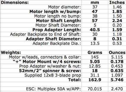 The "T" connector was replaced with Anderson Power Poles (APP) connectors on the MULTIPLEX MULTIcont BL-50 SD 50A ESC for 3-4S LiPo. The Kv was determined as 645 using the drill press method. Later, once the motor prop test data was entered into Drive Calculator, it calculated a Kv of 642. A freshly charged 4S1P 2300mAh "A123" pack was used as the power source for the motor/ESC/prop data gathering. The motor was placed on the test stand with an Emeter II inline. The supplied ESC did not work correctly with the Emeter II's 'servo controller'. A Castle Creations Phoenix Ice 50 was used for the data collection. The Ice 50 data was not used. No load data was collected and then data for an APC 14x10E, APC 14x7E, Hitec 12x8 3-blade, APC 13x6.5E and a second no load data point. All of the data was collected on the same battery charge. The volts, amps and RPM data, saved to the Emeter II Snapshot area, were entered into a new motor in Drive Calculator. The supplied ESC was tried again. This time I used my Tactic TTX650 transmitter and a TR624 receiver. The ESC would still 'go past' full throttle and then the RPM and amps would drop. I tried to calibrated the ESC to my Tactic TTX650, while the motor was still secured on the test stand. I moved the throttle stick to full on and then plugged in the battery. In a few seconds I heard some tones and lowered the throttle to off. There were more tones in the 'off' position. Unfortunately, that did not help, and the throttle still reached maximum RPM at about 80% throttle stick movement and then the RPM and amp draw dropped down as the throttle was moved to the 100% movement position. There is nothing in the Hitec or Multiplex manuals for this plane that indicates how to adjust the throttle range on the ESC. I contacted HitecRCD by phone on 06/05/2014 and Tony O. said that they would replace the ESC. 06/05/2014
Using the Ice 50, and Tactic radio, a freshly charged battery, and APC 14x10E prop yielded; 11.7v, 30.2 amps, 5880 RPM and 360 watts in. The calculated pitch speed is 55.7 mph. I weighed all of the components that were actually going to be used. Ready to fly it should weigh 3.26 lb. for 110.4 watts in per pound. 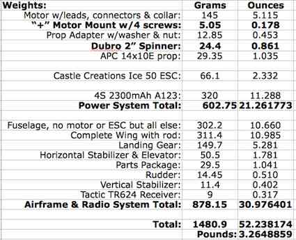 At 52.24 oz. the wing area loading (WAL) is 16.18 oz./sq.ft. and the wing cube loading (WCL) is 9. (Actual measured wing area follows.) While waiting for the plane to arrive, I used the overhead view and 3-view in the Hitec manual to check what the wing area might be as well as where an initial safe center of gravity (ISCG) might be. I was surprised that I got a significantly larger wing area than the Hitec's stated 418 sq.in. After the kit arrived, to check the actual wing area, I set up the wing panels using the rod joiner. After weighing 10 sheets of 8.5" x 11" printer paper (really 8-5/32" x 10-63/64") I laid them down in two columns by five rows. I laid the wing over the paper with a block to hold up the trailing edge and a brick on top to hold it down. The wing outline was drawn with a pencil. The drawing showed a root chord of 12.75", tip chord of 7.0625", sweep of 1" and half-span of 23.53125". The full span is 47-1/16". The math yields a wing area 465 sq.in. To use the paper weighing method, the wing area was cut from the paper sheets. The pieces that comprised the wing area were weighed. On this day, with the humidity here in my basement, the paper weighed 0.0487508989g/sq.in. The wing area paper weighed 22.8g. 22.8/0.0487508989 = 468 sq.in. Either way, the wing area is over 10% greater than that stated by the supplier. That's not a bad thing. I'm calling it 465 sq.in. To help calculate the ISCG, the horizontal stabilizer and elevator areas were drawn onto 4 sheets of paper. The area was measured and the stab/elevator area weighed and calculated. The Initial Safe CG was calculated at 2" behind the leading edge of the tip rib. That is about 76.2mm behind where the leading edge of the wing meets the fuselage, or about the recommended forward CG found in the Hitec manual. The Wing Area Conundrum I wanted to figure out why there was such a difference in wing area. After exploring the full-scale Extra sites it became apparent that the designer of this stand way off and squint scale model took a lot of liberties with the proportions, including the wing's aspect ratio and therefore its wing area.
The Assembly There area only 11 assembly steps. No glue is used in the assembly of the airframe. The first problem arose in Step 3: Vertical Stabilizer Assembly. The rear tab of the vertical stabilizer would not slide all the way down into its slot in the fuselage. It hit on something. After using a pin vice with a 1/16" bit in it to explore the slot in the fuselage, I found a "glue" of some type blocking the slot. A 7/64" bit was placed in an electric drill and the "glue" very, very carefully removed to allow the tab to seat. The screw hole for that tab was also filled with glue, but the pin vice, with the 1/16" drill bit, opened it up. Step 7: Connecting the Tail Wheel was difficult using the provided springs. One of the nylon control horns on the rudder did not have an open hole in it. The point a #11 blade in an X-Acto knife was used to open the hole. The screws in the swivel barrels are so close to the rudder that aligning the tail wheel and tightening them requires extreme patience and many, many tries to get the tailwheel and rudder aligned. Step 10: Receiver and Battery Installation could have been easier. The servo leads are numbered and represent the way the leads are supposed to be plugged into a receiver. Unfortunately, this does not apply to the way various transmitters assign channels or even Hitec. (See section dated 06/15/2014) Letters on the leads would have been better. A1 and A2 for the ailerons, T for the throttle, E for the elevator and R for the rudder, would have been helpful for setting up other transmitter and receiver combinations. There was no note on the outside of the box indicating that a "Y" harness was necessary to use with a 4-channel radio. The canopy is not glued down in certain places to the fuselage and the 'gaps' are noticeable. I wanted to change all of the pushrods to Z-bends and clevises to make manual adjustments at the field easier. I changed the elevator pushrod, but I was not able to change the aileron rods, at this time, as they could not be loosened using a 1.5mm allen wrench, and I was running out of time. The 1.5mm allen screws were stripped out and the wrench would not loosen them. My mission for this plane is precision aerobatics. I was able to reduce the elevator physical throw some, but not the ailerons. With the CG verified and control throws checked, it was ready for the field. 06/06/2014 The Maiden Flight
The plane, with its very small wheels and wheel spats, easily lifted from our field's close cropped grass. The flight was pretty uneventful. It only took a couple of clicks of up elevator and right rudder to get it flying reasonably well, really. The ailerons were 'overly sensitive', as expected, for my type of flying. Several rolls and loops were flown and a CG dive test completed. Everything was fine. The landing was a non-event and perfect. For the second flight, the aileron throw was reduced to 60% using the Tactic TTX650. The second flight was as good as the first with inverted flight, outside loops, knife-edge and point rolls added. I did notice a pronounced lean to the left in the vertical lines, which I corrected with right rudder. The power system seemed to be a perfect match for the type of flying I'm using it for; good high verticals and good sized loops. Flight 3 was just more 'getting used to it' with a bit more trimming. Keith Shaw flew flight four and really got it trimmed out nicely. I took several notes at the field about what I wanted to check and change on the plane to make it easier for me to fly. After returning home, I checked the lateral balance, which was perfect. I put small washers behind the left side of the motor mount to give it right thrust. In the Part 1 Video, found on the Hitec Extra 300S page, it was apparent that the plane would also benefit from right thrust when using the stock 3-blade prop and either the 3S or 4S LiPo batteries. Note the video at the 3:19 minute mark, 4:28 minute mark, 4:40 minute mark, 5:07 minute mark, 5:18 minute mark, and 5:50 minute mark. I removed the aileron pushrod system and replaced the rods with Z-bend and clevis rods. It was then that I noticed that the left and right ailerons did not have the same amount of throw. The left aileron went up 3/4" measured from the inboard end of the aileron and the right only 1/2". I noticed that the servo arms on the two servos were not at the same angle. That caused a differential difference between the two ailerons. I wanted to move the left aileron arm to a different spline, but the screws in the servo plate would not budge. Since the Tactic TTX650 is a 'computer' radio, I adjusted an arm's angle using the sub-trims. Using the sub-trims and servo travel adjustment, I was able to get the same throw on both ailerons. The throw was reduced on the ailerons by moving the servo arm end to the middle hole and and control horn end to the outer hole. Keith recommended increasing the elevator throw and adding 20% Expo to both the ailerons and elevator. That was completed. The Castle Creations Phoenix Ice 50 was adjusted following Castle's recommendation. 06/07/2014 Five flights were flown. The flying conditions were perfect with just a light wind from the east, which was right down the runway. It was much easier to set the trims using the clevises to make minor adjustments. The elevator felt too sensitive, but the ailerons were 'just right'. When I got home I changed the elevator back to the lowest throw and removed the Expo. I made up a Z-bend/clevis push rod for the rudder and installed it. The rudder is slightly 'bent' near the top and still requires some right rudder to correct it. The added right thrust worked out perfectly for the APC 14x10E prop. Vertical lines are truly vertical. 06/09/2014 There are some significant differences between my measured data and Hitec's and Multiplex's specifications from their manuals. 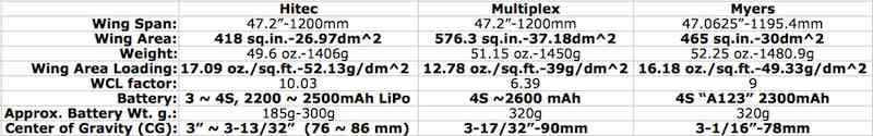 Notes:
The Hitec manual does not note any recommended throws. The Multiplex manual notes:
Rudder: 25 mm right / left 50% EXPO (~1" KM)
Unfortunately, the manual does not indicate where to measure from. I assumed the root tip of the aileron, as there is a bit of wing trailing edge there extending from the fuselage to use as reference and it is the widest part of the aileron. There were four flights today to determine the 'flying' CG and final trim. There was about a 45 degree crosswind with gusts at times. The landing gear popped off on a two bounce landing. It was the first less than perfect landing and it turned out that it was on flight 13, if you can believe that. It also happened when the CG was a tad too rearward. For the most part, the glue just 'let go' cleanly on both parts of the plywood landing gear mount. Some of the plywood delaminated on the inner most mount part. It didn't take long at home to have the mount back in place, glued in with medium CA, and the gear mounted again. The elevator clevis was moved into the center hole and 20% Expo added back into the elevator control in the transmitter. The rudder clevis was moved into the center hole for a bit more rudder throw and no Expo added. After taping various weights to the rear of the fuselage, just in front of the tailwheel mount, I decided to set the 'flying' CG 2.5" or 63.5mm behind the leading edge of the tip rib. When I measured the aileron movement up, I found that both ailerons had 9/16" up movement and 9/16" of down. I used the differential function of the Tactic TTX650 so that the up ailerons moved up 9/16" or 14.3mm and down was 3/8" or 9.5mm. I was surprised that I had independently arrived at approximately the same throws as suggested by Multiplex for the up movement on the ailerons. 06/11/2014
06/12/2014
The rudder was adjusted and it was then that I noticed that the vertical stabilizer "wags" with the rudder movement. The rudder does not return to the same position after it is moved to the right as it does when it is moved to the left. The Expo on the elevator was moved to -30 from +20 after I reread the manual and observed the movement. That's the way it works with a Tactic TTX650 transmitter. Since I was unfamiliar with Expo, I'd adjusted it in the wrong direction. It should be better now. 06/14/2014
The replacement ESC arrived today from Hitec while I was at the flying field. 06/15/2014
I set it up with the Tactic TTX650 and TR624 receiver instead of the Emeter II servo tester function and it did exactly the same thing. I decided to try and recalibrate the ESC. That didn't help. I next reduced the throttle throw to 87% on the transmitter. I recalibrated the ESC by having the throttle stick set about 1/2 way and then plugged the ESC into the battery. I moved the throttle stick on the transmitter to full and the ESC beeps began. There are a lot of them and they are continuous. After three sets of four tones each I moved the throttle stick to off. The ESC beeped. When the throttle was moved to full stick, the RPM and amp draw went up and did not go down. Unfortunately, after a lot of different throttle throw percents between 85% and 90% and a recalibration each time, I was not able to reach the power level achieved by the Castle ESC; 11.7v, 30.2 amps, 5880 RPM and 360 watts in. The best I could achieve with the Multiplex ESC was 11.72v, 27.9 amps, 5634 RPM and 327 watts in. Keep in mind that the same battery, motor, prop and radio system were used for both tests. Obviously, the Castle ESC has a bit lower resistance, is a bit more efficient and allows for a wider throttle range setting. Next I did a test using my Hitec Optic 6 with 2.4GHz module and a Hitec Optima 7 receiver. The first thing I found 'interesting' was that the throttle receiver slot is number 3 when using the Optic 6 (not Optic 6 Sport 2.4GHz), not number 4 as indicated on the ESC plug. The freshly charged battery and Optima 7 were set up on the test stand with the Emeter II inline with the replacement ESC. The ESC did NOT have the problem of going up to a certain point and then going down in RPM and amps. Unfortunately, the best data I could gather with this setup was; 12.5V, 21.2 amps, 5245 RPM and 265 watts in. The APC 14x10E was mounted for all of the previous tests. I decided to leave the Castle Creations Phoenix Ice 50 in the plane. A Few Thoughts: The quality control could have been much, much better on the one I received. The information-less ESC didn't play nicely with the Emeter II or Tactic TTX650 transmitter, nor did it reach full power when used with my Hitec radio system. The glue in the rear slot for the vertical stabilizer tab, grub screws in the aileron EZ connectors that could not be unscrewed, a wobbling vertical stabilizer when the rudder is moved, the non-centering rudder, gaps in the canopy where it is glued to the fuselage and the warped or 'bent' elevator and rudder are really not acceptable. Since one person can easily hold the plane inverted for a CG check, using measurements at the wing tips instead of the junction of the fuselage and wing could have been more helpful. Overall, the Hitec version of the manual is slightly better, with its assembly photos, compared to the Multiplex manual. Unfortunately, Hitec chose not to include the recommended throws for the rudder, elevator and ailerons. The movable surface throws for the 'classic aerobatic schedule' cannot be achieved using a physical setup on the servo horns and control horns. A computer radio is required to get the throws reduced. The outside of the box under 'Required for Operation' does not note a "Y" connector is needed if a 4-channel receiver is to be used. User Level 3 (Novice) on the box is misleading and absolutely incorrect. I don't use LiPo batteries, but there is no really good system provided to retain LiPo batteries safely in the fuselage during high 'G' aerobatics. That is left up to the user to figure out. I was not pleased that Tony O., at HitecRCD, asked me to send a copy of my Tower Hobbies invoice via email for my replacement ESC, which I did at 11:51:57 AM EDT on June 5, and then didn't follow up on it because it went to his spam folder. My follow up email at 4:40:04 PM EDT on June 10 also went to his spam folder. I was extremely surprised to learn that a business like HitecRCD uses a spam folder! The emails were both sent to the correct address; tonyo@hitecrcd.com. Lesson learned. 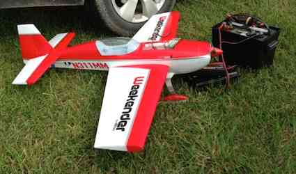
My Weekender Extra 300s Taking on Electrons The Final Verdict, and I'll bet you are not ready for this! I love this plane. If anything happened to it, I would replace it immediately. The packaging of the components is the best I've ever seen. The screw together engineering is awesome. Even though it is a stand way off and squint scale model, I enjoy that it looks like a real airplane. With the proper throws, it is an absolute joy to fly. UPDATE! 06/17/2014
UPDATE! 07/11/2017 (This update is not found in the .pdf version)
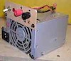
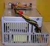
12 Volt Power Supply, How To
Hi Ken, Continued thanks for the Ampeer newsletter. I recently replaced two old desktop computers. Before sending them off to the recycle center I cannibalized them for some parts, including the power supplies. These make good 12 volt power supplies for RC battery chargers. With just a few bucks in parts (Radio Shack) and some soldering you're in business. The conversion is detailed on "YouTube" videos - here's a link: www.youtube.com/watch?v=7k1-xwwURJc Mine were not high power (223W/300W) but they each provide 15 amps @ 12 volts - not bad. A 400W will typically provide around 22 amps. Here's a summary of the procedure: Have the ATX motherboard connector with the clip "facing you" and cut the 3rd and 4th wires from the right end (green and black). Solder these wires together as they "turn on" the power supply when the AC source is connected. Optionally (as I did) you can put an on/off switch here (I also added a "power on" 12 volt LED). Then any yellow wires will be positive 12 volts, and any black wires will be negative 12 volts (DC). Be careful when cutting all the remaining wires - insulate them with electrical tape, "liquid tape" or heat-shrink tubing, making sure they can not contact each other or short against the metal case. The "Bestec" power supply had enough room internally for me to install everything in the existing case. If you do this make sure the banana terminals are properly installed with the insulating washers so they don't short against the metal case. The "Delta" did not have space, so I added a light-ply "panel" to mount the banana terminals, switch and LED, and mounted this externally to the power supply. Also, a good source for inexpensive computer power supplies is "Micro Center". Stay well,
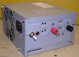
Bestec
Announcing the 30th Annual Mid-America Electric Flies Saturday, July 12 & Sunday, July 13
Here are the links to the 2014 Flyer as well as the field map and local area hotels list. 2014 Map to the flying field and local hotels listing |
To Reach Ken Myers, you can land mail to the address at the top of the page. My E-mail address is: KMyersEFO@theampeer.org