Flying High With Electric Power!

The Ampeer ON-LINE!
June 2001
The Club Newsletter of the Electric Flyers Only, Inc
AMA Charter 2354
Walled Lake, MI, USA

Editor: Ken Myers

Fly the Future - Fly Electric!

What's On This Site:
Site Table of Contents

President:Vice-President:Secretary/Treasurer:
Ken MyersRichard Utkan 
1911 Bradshaw Ct.240 Cabinet 
Walled Lake, MI 48390Milford, MI 48381 
(248) 669-8124(248) 685-1705 
Board of Directors:Board of Directors:Ampeer Editor
Jim McNeelyJeff HauserKen Myers
4733 Crows Nest Ct.18200 Rosetta1911 Bradshaw Ct.
Brighton, MI 48116Eastpointe, MI 48021Walled Lake, MI 48390
(810) 220-2297(810) 772-2499(248) 669-8124
Mailed Ampeer subscriptions are $10 a year US & Canada and $17 a year world wide. FREE on-line!
The Next Meeting: Date: Saturday, June 2 Place: Midwest R/C Society 5 Mi. Rd. Field Time: 10:00 a.m.

What's In This Issue?
Recommendations for Electric Powered Flight Systems (continued) Team B-52 Canceled 2 oz. Indoor R/C for Under $50 P-51 & P-47 Sanyo CP-1300SCR's are here!!
The May EFO Meeting: or our M.I.S.S. Adventure The Upcoming June Meeting North Shore MAC -Auckland NZ-Electric promotion and annual rally Meet Date Change Electric Control Line (ECL) Sport & Stunt
Grumman BearCat in Spain Your LT-25 Mid-Am 2001 Info Upcoming Events Send Ken email

Recommendations for Electric Powered Flight Systems (continued)
By Ken Myers
Part 1: March 2001 Ampeer

Part 3
Into the Unknown

     The rules of thumb (see noted issues) supply a lot of information about a proposed project, but they still do not answer the question about which power system to use. The rules of thumb only narrow the range of power system choices. While this is basically enough information for a veteran electric flier to have some idea of where to start, it is not enough information to help the beginner to electrically powered flight.

Selecting the Power System

     Before brushless motors and relatively high discharge rate NiMH (nickel-metal hydride) cells, it was a fairly straightforward process to get an idea of the motor and battery to be used based on the weight of the power system. Unfortunately, the process has become even more complex. Each month in the Ampeer, I will be spotlighting a popular, easily obtainable motor and it’s appropriate uses. Whenever possible, real world results will be included with the simulations. The data will also be posted on the EFO site: http://members.aol.com/KMyersEFO. This should make selecting the appropriate power system much easier, once the knowledge base has increased.

Back Figuring

     If part of the aircraft system is already known, such as the weight of a power system, or the weight of the finished airframe or even the weight of the onboard radio system, the proposed plane can be "back figured" for the type of plane and performance desired.
     Once the finished weight is estimated, the wing area can be estimated using:

(weight / flight factor * 144) ¾
(/ means divided by, * means multiplied by - always divide first)

Back Figuring Using Finished Airframe Weight

     If the finished airframe weight is known because it is already completed, the rest of the components can be back figured using the type of aircraft and expected performance. The Carl Goldberg Mirage 550 is used for example, because I am familiar with it. It is a trainer type aircraft and should have moderate performance, therefore it’s Flight Factors for predicting target weight is 2 and maximum weight is 2.5.

finished airframe weight back figured for the Goldberg Mirage 550
typical finished airframe weight = about 16 oz.
total aircraft weight = finished airframe weight * the inverse of 30% (the inverse of 30% is 1 / 0.30 or 3.333333)
16*3.3333333 = 53 ounces (note: this is 7 oz. above the highest Goldberg recommendation)
The next two steps, finding the wing area range are not necessary and can be omitted from the procedure if you wish. They supply information that you may want to keep for future reference.
wing area back figured using target weight flight factor = (finished weight of the aircraft / flight factor * 144) 3/4
wing area back figured using target weight flight factor = (53 / 2 * 144)3/4 = 485.52 sq.in. (53 is the "back figured" target weight, 2 is the target weight flight factor for this type of aircraft, 144 is the number of sq.in. in a sq.ft.)
wing area back figured using maximum weight flight factor = (53 / 2.5 * 144) 3/4 = 410.7 sq.in.

     While the above two steps weren’t necessary, they do supply some interesting information. As can be seen above, a 53 ounce flying weight moderate performance type may have a wing area from 410 sq.in. to 485 sq.in.
airborne radio weight = up to 15% of the total weight
airborne radio weight = 53 * 0.15 = up to 7.95 oz.
power system weight = about 55% of the total weight
power system weight = 53 * 0.55 = up to 29.15 oz.

     This is an interesting result, since the recommended power system of 6 cells and the Turbo 550 motor is only about 19 ounces and their recommended radio system is 9.6 oz. for the 3-channel version. It seems to me that the recommended airborne radio system is too heavy and the recommended power system is too light.

Back Figuring Using Airborne Radio System Weight

     In general, this would be an unusual use, but it can be done.

     A typical "standard" 3-channel airborne radio weight using 3 standard servos (1.6 oz. each)(Goldberg doesn’t use an ESC, just an on/off switch controlled by a servo), a standard receiver (1.4 oz.), and standard 600 mAh Rx pack (3.6 oz.) = 9.8 oz.
Total finished airframe weight = airborne radio weight times the inverse of 15%
9.8 * 6.6666666 = 65.3 oz. (note this is 18 - 26 ounces above the Goldberg recommendation!)
wing area using target weight flight factor = (65.3 / 2 * 144) 3/4 = 568 sq.in.
wing area using maximum weight flight factor = (65.3 / 2.5 * 144) 3/4 = 480.29 sq.in.
finished airframe weight = 65.3 * 0.3 = 19.6 oz.
power system weight = 65.3 * 0.55 = 35.9 oz.

     It seems that a "standard" 3-channel airborne radio system is too heavy for this proposed project.

Back Figuring Using Power System Weight

     Many people have a motor and cells and want to know what it can power.
power system back figured = 19 oz. (Turbo 550 and 6 RC2000 cells, recommended 6 cell operation)
19*1.8181818 (inverse of 55%) = 34.55 oz. (5 - 10 ounces under the weight noted in the Mirage 550 directions)
wing area using target weight flight factor = (34.55 / 2 * 144) 3/4 = 352 sq.in.
wing area using maximum weight flight factor = (34.55 / 2.5 * 144) 3/4 = 298 sq.in.
finished airframe weight = 34.55 * 0.3 = 10.37 oz.
airborne radio weight = 34.55 * 0.15 = 5.18 oz.

     At 464 sq.in. and with a finished airframe weight of 16 ounces, it appears that the Goldberg Mirage 550 is too big and heavy for this power system to fly it as a moderate performance aircraft.

What Is Needed to Fly the Goldberg Mirage 550 As a Successful Trainer Type Moderate Performance Aircraft?

target weight (464 / 144) * (4641/3 * 2) = 49.89 oz.
maximum weight (464 / 144) * (4641/3 * 2.5) = 62.36 oz.
finished airframe 49.89 * 0.3 = 14.97 oz. to 62.36 * 0.3 = 18.71 oz.
airborne radio system 49.89 * 0.15 = 7.48 oz. to 62.36 * 0.15 = 9.35 oz.
power system weight 49.89 * 0.55 = 27.44 oz. to 62.36 * 0.55 = 34.3 oz.
starting prop diameter (uses the target weight not maximum weight)
SQRT ((49.89 * 1.25) / Pi) * 2 = 8.91 rounded to 9
pitch to try would be 6, derived from 9 * .65 = 5.85 rounded to 6
watts out 49.89 / 16 * 45 = 140.32 watts out
required RPM (140.32 / ((9/12)4*(6/12)*1.31))1/3 = 8.781 KRPM or 8,781 RPM using a "typical" wooden prop

     My current rules of thumb differ from Keith’s earlier ones as presented in his "Electric Sport Scale" article. He suggested 40 - 60 watts per pound of input power for mild aerobatics, which a trainer should be able to do. Using Astro Flight cobalt motors, the range would be approximately 30 watts to 45 watts of output per pound assuming 75% efficiency. My current recommendation, as shown above, is at the top end of Keith’s range at 45 watts out per pound, so what is the difference? While Keith’s recommendation is the top of his range, it is the bottom end of my recommendation.
     The biggest difference comes when applying watts out to ferrite and brushless motors. While Keith’s recommend input watts works well for Astro Flight cobalt motors, the watts out per pound is significant when looked at for ferrite and brushless motors. To get approximately 140 watts out with an Astro Flight cobalt motor, you need approximately 187 input watts. To get approximately 140 watts out on a ferrite motor, you need approximately 215 or more watts of input power. To get approximately 140 watts out on a brushless motor, you need approximately 165 watts of input power or less. Watts out sets the target that is to be reached or exceeded by any type of motor to provide a "good" flying type.
     Another way to look at it would be to compare the cell count at 25 amps. At an amp draw of about 25 amps, the brushless motor would need about 7 cells, the Astro Flight cobalt about 8 cells and the ferrite about 9 cells or possibly 10 because most, not all, ferrite type motors are overall much less efficient at 25 amps when compared to a brushless or Astro Flight cobalt motor.

     This is all nice to know information, but will the motor supplied in the Goldberg 550 kit fly this plane as a trainer type?

The Goldberg Turbo 550 Motor

     This month’s motor is the Goldberg Turbo 550. I have two of them; therefore I can test them and give real world results.

     First, I checked my motor data to see if I had the specs for the motor. I didn’t. Next, I went to the MotoCalc database, which is part of the MotoCalc computer program by Capable Computing (www.capable.on.ca) and got the following motor data; Kv = 2528 Io = 2 Ra = .085 Weight = 7.8 ounces. I played around with these numbers on my spreadsheet and said, "Huh! This motor looks too good on paper, compared to how I’ve seen it perform." I weighed the motor. It weighed 6.8 ounces. Humm. I remembered that Bob Kopski had tested this motor and looked up his data in his Model Aviation, July 1989 column, p. 48. He also had two samples of this motor and found; Motor #1 Kv = 2049, Ra = 0.093 and Motor #2 Kv = 2039, Ra = 0.100. The Io was not given. Big difference. There was only one thing left to do, test my motors.

     I measured the Kv of each of my motors using a reversible drill switched into reverse. I measured the RPM using a digital tack to read the paint lines located 180 degrees opposite each other on the drill collet and measured the voltage with a digital multi-meter for each motor. The average Kv for both motors was 2233. Many tests were conducted over a five-day period, with the meter readings recorded on videotape and played back and paused to get both numbers at the same time. Next the motor resistance was determined by running both motors and measuring the RPM with a digital tachometer, the amps with a digital ammeter and volts with a digital voltmeter, all being recorded on tape, with several tests of each motor taking place. The motor resistance was calculated by dividing the measured RPM by the RPM per volt. The result is the back EMF. The back EMF is divided by the amp draw and yields the resistance. The average resistance for both motors yielded 0.126 ohms. The Io was measured using 4 cells and found to be 1.1 amps on both motors. Both motors had been broken in.

     My results didn’t match either MotoCalc or Bob Kopski’s measurements. I proceeded with real world results. This is what I measured with an 8x4 Grish prop:
Motor #1: 6-cell RC2000 pack: 8960 RPM, 6.48 volts, 16.6 amps
Motor #2: 6-cell RC2000 pack: 9000 RPM, 6.38 volts, 17.0 amps
Motor #1: 7-cell 900SCR pack: 9,950 RPM, 7.31 volts, 20.8 amps
Motor #2: 7-cell 900SCR pack: 9,900 RPM, 7.28 volts, 20.4 amps
This is what I predicted for a typical 8x4 prop.
6-cell 2000RC pack: 9,300 RPM, 6.42 volts, 17.9 amps, 70 watts out, 60% eff.
7-cell 900SCR pack: 10,300 RPM, 7.35 volts, 21.6 amps, 95 watts out, 59% eff.

     The predictions were within 4% for RPM and 5% for the amp draw; therefore I was convinced that I had close to the correct values for the two particular motors that I have. How I made these predictions can be found later in this section.

     I decided that I wanted to do a test with a belt-drive and attached the MFA belt-drive with a ratio of 2.222222:1 to Motor #1. I attached the belt drive and retested for the resistance and Io, since both the resistance and Io go up when a belt drive is added. The tests yielded the following: Kv = 2233 Ra = .155 Io = 2
Actual test with Top Flight Super M 10x6 prop
Motor #1: 9-cell 1250SCR: 6,800 RPM, 9.57 volts, 17.6 amps
Predicted with a typical 10x6 prop:
9-cell 1250SCR: 6,950 RPM (2% difference), 9.56, 18.1 (2.7% difference) amps, 107 watts outs, 64% eff.
     With the actual test results closely matching the real world, I prepared the following information for the Goldberg Turbo 550 motor using the following formulas:
Motor Formulas
volts to motor = (1.25 * number of cells) - (number of cells * cell resistance * amps) - (0.03 * amps) 1.25 is cell voltage, 0.03 is system resistance to the motor and includes wire and ESC
watts out = (volts to the motor - (motor resistance Ra * amps)) * (amps - Io)
RPM = (volts to the motor - (motor resistance Ra * amps)) * RPM per volt (Kv)
motor efficiency = watts out / (volts to the motor * amps)
system efficiency = watts out / (1.25 * number of cells * amps)

Cell Amp Draws, Weights and Resistance for Estimation Purposes:

10 amps, 0.7 oz., cell resistance = 0.012
15 amps, 1.2 oz., cell resistance = 0.012
20 amps, 1.5 oz., cell resistance = 0.0077
25 amps, 2.0 oz., cell resistance = 0.0077

Estimating and Refining Motor Performance

     Motor approximations are just that, but they do help in predicting what a specific motor might be capable of. The more accurate the input data of Kv, Ra and Io, the more accurate the predictions will be. With my two motors, the predictions would have been way off, had I not realized that the published data didn’t match my motors. Later I’ll cover again, step by step, how to measure motor constants on the brushed motors that you have. You can find published motor constants at the EFO site, various sites online and in the "Calc" programs.
     When I look at uses for a motor, I do it by process of elimination.

(The process will be discussed next month.)

Return to "What's In This Issue?"

Team B-52 Canceled
From: James Frolik jdfrolik@freenet.de

     Regretfully I have canceled the purchase of Chris Golds' beautiful B-52 model and Team B-52 will return all monetary donations.
     Each donor has received a detailed notification, but for the general public's information it's enough to say the decision to cancel was based on a number of compounding difficulties, the foremost being a transport delay and the ensuing logistics it created.
     Noel Martin will return all money and you may contact him at noel@viclink.com should you have any questions; or contact me, James Frolik, at either of the E-mail addresses below.
     It would have been very impressive and exciting had the plane completed the itinerary I envisioned, and I sincerely apologize for any letdown in any heightened expectations.
Yours sincerely,
James Frolik, Cologne, Germany
jdfrolik@hotmail.com or jdfrolik@freenet.de

Return to "What's In This Issue?"

2 oz. Indoor R/C for Under $50
From: Allan Wright aew@mediaone.net

The Less than 50

Ken,

     I'm not sure this is something you want for the Ampeer or not, but I've recently completed an indoor R/C project 'on the cheap' using parts from Wal-Mart and Radio shack. The completed airplane with transmitter, receiver, motor and airframe cost just around $50. For anyone interested I put up a nice little website documenting my adventure at: pease1.sr.unh.edu/aew/rc/cannedheat
     Thanks for all your good work for the hobby,
Allan Wright

Return to "What's In This Issue?"

P-51 & P-47
From: Mark Rittinger mrittinger70@hotmail.com

Mark's P-51

     Thought you might want to see my latest project....
This is a 42" foam and balsa '51.
Specs: Span 42", Area 270
Power: MM reverse 3.5:1 MAS box, 12-10 APC prop
Cells 10 -1250 SCR's
Construction: Pink foam wing w/ 1/32 sheet. Pink foam fuselage, covered with women’s nylons, and Zpoxy resin, finished with Presto. Wood parts will be Ultracote Chrome.
     Landing gear is for display only (all they do is act as carrier hooks on ships that small!)

Mark's P-47

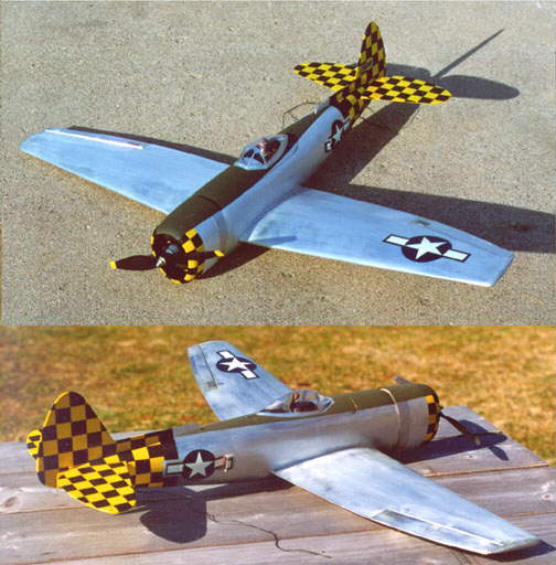
     The Jug has same specs and came out at 45 oz FLIES GREAT!!!!! Looking forward to Mid Am again :)
     Working on Black Widow S400 plans ......

Return to "What's In This Issue?"

Sanyo CP-1300SCR's are here!!
From: Ralph Weaver rmw00@yahoo.com

     These cells are 34g or 1.19 oz. with heat shrink (an N-1250SCR is about 40-45g) and weigh the same as 800AR cells. They are sub-C diameter, but only 1" tall. They are the same technology as the new RC2400 and perform well at higher currents. I'm going to post some graphs tonight.
     The cells were difficult to get and will be $5 for now. The price may come down a bit as they become easier to get.

(INFO from Ralph’s Site)

Cell Specifications Nominal Voltage 1.2V
Typical Capacity at C/5 1300 mAh
Impedance at 1000Hz 7.8 mOhm
Diameter 23mm
Height 25mm
Weight 33g
Test Data Capacity
Cell Capacity at 20A
CP-1300SCR1100 mAh
Sanyo N-1250SCR1272 mAh

For comparison: N-800AR specs:
Weight: 32g
Diameter: 17mm
Height: 50mm
Capacity at 20A: 810 mAh
Measured Internal Resistance: 7.8 mOhm
     My site www.ralphweaver.com
     MTI products www.magtechinc.net

     (The new Sanyo CP-1700 cell should be available from various sources in the US by the time you read this. It is a Sanyo cell with about 1700 mAh in a 1250SCR size and weight. KM)

Return to "What's In This Issue?"

The May EFO Meeting: or our M.I.S.S. Adventure

     Sunday, May 6, dawned cool and windy. Not the kind of day that we had hoped for! Although the day was bleak, changing to sunny, the wind changed also, becoming even windier.
     This did not deter a great time, or even the electric flying by the EFO, M.I.S.S members and guests.
     Shortly after arriving, Ken mowed a small strip in the long grass of the flying field, and tested the 15+ MPH wind with his X-250, of course this was after Pete Foss had put up a good flight with his ElectroStreak. ;-) Soon the air had a constant flow of electrics, as the M.I.S.S. folks elected not to set up their winches, but with the good turnout of EFO members and M.I.S.S. members with electrics, the flying continued all day. Surprisingly, there were no mishaps due to the high winds.
     The M.I.S.S. provided a great "field lunch" with the EFO pitching in a little bit. What a wonderful group. The EFO thanks M.I.S.S. a ton.
     After lunch, the flying continued well into the windy, but sunny afternoon.
     While not a day for Park Flyers or sailplanes, it was a wonderful day. The friendships between the M.I.S.S. members and EFO is amazing. Camp Dearborn, in Milford, MI is a good place to fly and it is always a fun day. We are looking forward to more joint ventures like this one!

Return to "What's In This Issue?"

The Upcoming June Meeting

     The June EFO meeting will be a flying one. It will be held at the Midwest R/C Society Flying field located on 5 Mi. Road in Northville Township. The date is set for Saturday, June 2. Any electric fliers in the area are invited to join the EFO members in a day of flying and talking electric flight. An AMA card is REQUIRED to fly. We will be meeting at 10:00 a.m. Should the weather prove to be too foul, the meeting will be on Saturday, June 16, at Midwest. If the weather is "iffy" on June 2, please give Ken a call at 248.669.8124 to see if it is a go or no.

Return to "What's In This Issue?"

North Shore MAC -Auckland NZ-Electric promotion and annual rally
By Lex Davidson lex.davidson@paradise.net.nz

     Our club is typical of most here in New Zealand. About 40-45 members and about 25% to 30% of the members are regulars at the field. Unlike most clubs quite a few of the very active members rarely fly anything but electric powered models. There are another ½ dozen who are dabbling and having good success. In other words most of the active members are flying electric models regularly.
     Members have seen that electric flight isn’t about staggering under-powered gliders and that virtually anything can be converted to electric if a few "rules" are followed they can be as sure of success with an electric model as with any other model type.
     I think the reason why we have so many of the members "having a go" is because the "dedicated" electric fliers have not "over-sold" electric flight. As with all aspects of aeromodelling there are many solutions, many directions and alternatives and starting can be very, very confusing. By making information available, pointing interested persons [not just members] at good information sources, reliable suppliers and down proven paths----without "preaching", or, pretending that electric’s are cheap, we have become the club with the strongest E activity in the country.
     Because of member interest we have been able to adopted a one design sport s400 pylon racer and have made available to members a "kit" digital ESC suitable for the pylon model (it is expandable to handle s600 type motors) and we have run our second Electric rally.
     The rally was a huge success. Twice as many registered as in 2000. At mid-day there were 50 cars on the field and over 100 people. A great day supported by the local clubs (18 in the Auckland region) and with visitors driving up to 7 hours, each way, to be there. All but two persons who registered in 2000 was back for this years event!!! Both sent their apologises this year.
     For next year the guys are asking for 2 days, with camping and night flying. We will just have to see about that.
     On the day-absolutely perfect weather. Most of the time there was just enough wind to indicate which way to take off and circuit. Because it was so light slow flies and park flies could fly nearly all day.
     This was a true rally---defined by us as "yak and fly and yak fly". People were encouraged to bring stuff they wanted to pass on i.e. a boot sale. We had two of our local retailers on site. Our Mega, Kontronics, Aeronaut man and our Hitec supplier. I think their day at the field was worthwhile.
     Lots of cold drink needed to help cope with the heat.
     Models - everything from small park fliers to brushless powered F5F models [international class 10 cell gliders], a Goldberg Chipmunk with 24 cell and most impressive-a big foam Hercules powered with geared MFA Rocket motors. No serious crashes. Unfortunately I can claim the most impressive. My A10 rocketed off the S&EM bungees release and shed its wing about 3 meters off the ground. Fuselage with motors/ fans going full bore continued for a very worthwhile distance before being overcome by gravity!!!-AND no one got a photo!

It's a Herc!

     The Herc was built from the plans on the Arieane web site. It had only been finished in the motel the night before!!! The Herc and the team from Hastings got top prize for the effort. These things look so good in the air. It is hard to imagine anything similar being done with IC motors-without a lot more stress and expense. Some really beautiful models. The majority of models were built from plans or own designs.
     The only competition held was speed 400 pylon racing. Seven entrants. A lot of fun for those competing and the spectators. This was the 1st time the event had been run in New Zealand. As there aren’t any National rules we made up a set and circulated them before the rally. We adopted a 100-meter racetrack and flew or tried to fly 10 laps. The winner of race 1 (only one finished) flew against the two who finished in race 2.
     Paul Lalande, our local Knotronics and Mega supplier put up excellent prizes for the event.
     Last to go left the field at about 7:00 P.M., a very long hot day.
     We will do it again next year and would love to host any off shore fliers. Overseas visitors only have to be signed into the visitors book for the day and demonstrate they know what they are doing before they can fly with us!!!! No special license or insurance requirements.

Return to "What's In This Issue?"

Meet Date Change

     August 18 - tentative Columbus, OH E-meet at the WMAA field just north of Columbus, Ohio. It will be a fun fly type event, similar to the one that Azarr has put on in the past.
     Here is our web site: wmaa-wags.org/Default.htm. It has some map and field info. Kevin Petrilla petrilla.3@osu.edu
     NOTE: This event will likely be moved to august 18th so as not to coincide with Pat's event in Fort Wayne. I am waiting on approval from the club officers. I will keep you posted.
Thanks, Kevin

Return to "What's In This Issue?"

Electric Control Line (ECL) Sport & Stunt
From: Hillsdale Flyers hiflyers@csnet.net

     Our AMA Chartered Club #4210 is primarily interested in Electric Control Line (ECL) sport flying (stunt style) for kids 6 through 18 and youth of ALL ages. We ask you to develop and promote the growth of ECL!
     Consensus of the "experts" in both control line and electric have advised us that our ECL (only) Club needs:

  1. RTF’s and ARF’s that fly on 20 foot lines minimum
  2. Planes that are simple and economical (durable too)
  3. Three planes (at least):
    • "Primary Trainer" a ROG that goes "round and round"
    • "Basic Trainer" that also loops and flies inverted
    • "Advanced Type" that does it ALL (The "Holy Grail" of ECL that conquers AMA and FAI patterns)

     We believe we are a start in a growing revolution and that ECL’s will be flown indoors, in school yards, ball fields, soccer fields, parking lots, and backyards worldwide. What a very rewarding, commercially viable niche market. And….. Oh, the rewards to our youth!
     We need a Basic Trainer (now) and Advanced Type RTF/ARF’s by next spring. Please advise availability and cost. Will you HELP?
Respectfully submitted,
George Yatsko - Director
Phone: 201 666 4565 fax: 201 722 3876 hiflyers@csnet.net

     Okay folks, how about some help for George? You can reach him directly as noted above.

Return to "What's In This Issue?"

Grumman BearCat in Spain
From: Diego Lopez Muñoz/Vias y Construcciones Diego_Lopez_Mu0xL1A4zozVias_y_Construcciones@vycsa.es

Spanish BearCat!

Dear Ken,

     I write from Spain, my name is Diego López.
     You can see my Grumman BearCat under construction at: www.terra.es/personal/diego_lopez/modelos.htm Last Saturday it flies, and I am very happy with the results. Soon I can offer you videos of the flight.

Return to "What's In This Issue?"

Your LT-25
From: John Lewis hjohnlewis@compuserve.com

Hi Ken,

     I do not expect you to remember me, but thanks to you I am slowly getting into this fine hobby.
     I normally live in Kansas City, but also have a house here in Europe, on the island of Jersey, from which we named our state of New Jersey. It is 15 miles from France and approximately 150 miles south of England, relatively close to Mont St. Michel.
     During this winter, I have tried to fly "your LT-25". I call it this, as it was built exactly as you advised on your web site. The weather has not been very kind and I have only managed about fifteen flights, with your plane.
     There have been two major rebuilds from two crashes but I am very close to going solo. If I may make a suggestion, to add to your advice on getting started in this hobby, I would strongly advise a beginner to buy a computer program, as I flew mine almost every day. My instructor was surprised at my coordination and control. It is a little frustrating that I do not fly while we are here in Europe.

The LT-25

     The point of this e-mail is to show you "your LT-25" which as you can see, from the last rebuild has a slightly different nose, ( I had to remake everything including the firewall forward).

The Rascal

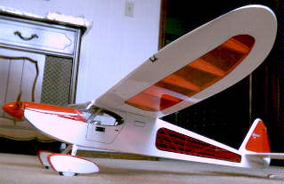
     I am proud of the Sig Rascal as it gave me the chance to learn some new building and covering methods.
     It has an Astro 802G 3.3:1, an APC 8x6 electric prop and 7 Sanyo 600AE cells. NOT FLOWN. But it did win the Shawnee Mission RCC "model of the month" award for March.

The Amptique

     The last is an Amptique with a Kontronic BL480-33 brushless motor 4.4:1 gearbox, a 9x5 Graupner slim prop and 7 cells 1250 mAh. I did take your advice and strengthen the rear under and forward of the horizontal stabilizer. Also NOT FLOWN yet!
     I hope that this has not been too boring, and trust that we will have the chance to meet soon.

Return to "What's In This Issue?"

Mid-America Electric Flies
AMA Sanctioned
Saturday, July 7 & Sunday, July 8, 2001
Hosted by the:
Ann Arbor Falcons and Electric Flyers Only
Site Provided by the:
Midwest R/C Society
your Contest Directors are:
Ken Myers phone (248) 669-8124 or KMyersEFO@aol.com
Keith Shaw (734) 973-6309
Flying both days is at the Midwest R/C Society Flying Field - 5 Mile Rd., Northville Twp., MI
Registration: 9 A.M. both days
Flying from 10 A.M. to 5 P.M.
Narrowband Transmitters are required - Channels 00 through 60, six 27Mhz frequencies, & eight 53MHz frequencies, will be in use. Flying on five 49 MHz frequencies may be accommodated on request - Narrowband receivers are recommended for flying on Channels 00 - 60 - Very Wideband 27, 49, & 53 MHz, receivers may be accommodated on request
Pilot Entry Fee $10 each day - - - - Parking Donation from Spectators Requested
Saturday’s Events

All Up - Last Down, Longest Timed Flight, Best Scale, Most Beautiful, Best Ducted Fan, Best Sport Plane, CD’s Choice
Sunday’s Events
All Up - Last Down S400 only, Longest Timed Flight S400 only, Best Scale, Most Beautiful, Best Mini-Electric, Best Multi-motor, CD’s Choice
All Planes Must Fly To Be Considered for Any Award
Night Flying Possible, Weather Permitting, Friday & Saturday Nights

Refreshments will be available at the field both days.
There will be a pot-luck picnic at the field on Saturday evening.
Come and join us for two days of fun and relaxed electric flying.
Even though this is called a contest, the purpose is fun and the enjoyment of sharing the electric experience.
Come, Look, Listen, Learn - Fly Electric - Fly the Future!
Saturday’s & Sunday’s Awards:
Plaques for 1st in each category
Merchandise drawing for ALL entrants

Return to "What's In This Issue?"

To Reach Ken Myers, you can land mail to the address at the top of the page. My E-mail address is: KMyersEFO@aol.com
EFO WEBsite: http://members.aol.com/KMyersEFO/