I then imported an image of the front of the plans into my CAD program and drew just the essential lines and scaled them to determine the prop diameter.
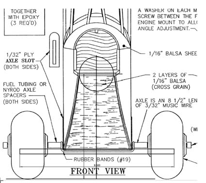
Front with scaling completed
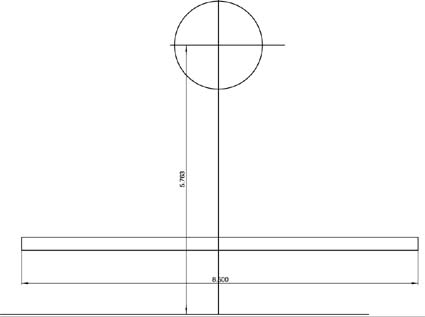
Scaling showing a ground to center of motor shaft clearance of 5.763 inches
Without repositioning the motor, it looks like you can get by with a 10" diameter prop if you have pavement, exceptionally short grass, bare ground to take off from or if you use a hand launch. A 9.5" diameter prop should give enough ground clearance for normal grass flying field takeoffs.
The plane's mission is to fly around gently as a floater. With 638 sq.in. of wing area and a wing cube loading (WCL) of between 3 oz./cu.ft. to 5 oz./cu.ft. the ready-to-fly (RTF) weight would be between 28 oz. and 46.5 oz. My guess is that it will come out right in the middle of that range or pretty close to 37.25 oz. It certainly doesnŐt need more than 70 to 80 watts in per pound. That means that about 175 watts in would be a good target.
If you use a 3S Li-Poly, then 175 watts in / 11.1v = about 15.75 amps.
The speed control should be 15.75 amps * 1.25 (the inverse of 80%) which is about 20 amps.
The Li-Poly can be a 3S 1500mAh type.
The motor should weigh between 175 watts in / 3 watts per gram or 58g to 175 watts in / 1.75 watts per gram or 100 g.
You really want to go with a motor that is at the heavier end of the weight range for balance reasons. The original had a pretty hefty hunk of 'iron' there.
The motor Kv using an Aeronaut 9.5x6 Electric Flight Prop (9.5x6_electric_flight_prop_fiberglass_white_768_prd1.htm) should be about 1050. If you go with an APC 10x5E prop, then the motor Kv should be about 950.
I would do it just a bit differently from those numbers, even though the watts in would be more than necessary. This design needs weight in the nose. I would go with a heavy end motor and use the ubiquitous 3S 2100mAh/2200mAh Li-Poly pack.
An outrunner motor will be mounted further forward than the old ferrite motor and I'd get the pack as far forward as possible.
A setup that I would personally use:
Scorpion SII-3008-1090 95g (3834-1090, 95g)
Castle Creations Thunderbird-36 Brushless ESC
Hyperion G3 CX 2100mAh 3S 25C/45C
Drive Calculator indicates the following:
Aeronaut E-prop 9.5x6 10.69v, 19.1 amps, 204.5 watts in, 9269 RPM
APC 10x5E 10.66v, 20.7 amps, 220.3 watts in, 9032 RPM
Next, I went to RC Groups to see what I could find on the Lazy Bee. I actually wrote my reply before reading the following, which appears in the Scorpion motor thread on RC Groups. You'll find the original post about halfway down the page.
This is from the Scorpion motor thread on RC Groups:
Quote:
Originally Posted by phillipduran
I recently purchased a Scorpion SII-3008-1090KV motor and I'm wondering what ESC and battery I should go with. I'm in about week two of learning electric power systems and I'm still wandering through the woods. The plane it's going on should end up around 40oz and has a 48" wingspan. I'm going to stick with Scorpion for the ESC and after a bit of research I'm thinking a 35 amp ESC is what I need. Could I get away with a 25 amp? The plane is a Clancy Lazy Bee, so gentle easy flying is what the plane is made for. As for batteries, I don't have a clue so any suggestions would be appreciated. Flight times of at least 10 minutes would be fine with me. If that means I could go with a lighter battery and save weight, which would be great.
Answer from Lucien Miller of Innov8tive Designs:
I think this motor might be a lot of power for this plane, buts its built to handle up to a .20 size gasser so it's still going to end up lighter than it would with a glow power system.
Whenever you select an ESC for a motor, you should choose one that is at least equal to the highest current that the motor is rated for, even if you do not intend on running that much current. The Scorpion SII-3008-1090 motor has a max current draw of 26 amps, so I would go with the next standard size ESC available, which is the 35-amp model.
One thing that people forget to take into account is the surge current that you get every time you advance the throttle. Even though a motor may only pull 26 amps at full throttle, you will see currents of 30 or 35 amps for brief periods of time every time you goose the throttle. This is because the motor needs extra current to speed up, but once it gets to the new higher RPM, the current drops back down to the steady state value. That is why it is a very good idea to have an ESC that is one size larger than you really need, to be able to handle the current surges that you end up seeing.
That particular motor works very well with an APC 10x5 on 3 cells. You will get around 40 ounces of thrust with a current draw of 20 amps at full throttle. This is more than enough power for a Lazy Bee aircraft. Most of the time you will find yourself flying at half throttle, where you will only be pulling 9-10 amps of current. If you run a 3-cell 2200mah battery, this is only a 4 to 5C discharge rate, and will give 12-15 minutes of flying time per charge at reduced throttle, and 5-6 minutes of flying time at full throttle all the time. If you want to save a little weight, a 1500 or 1800mah battery can also be used with slightly shorter run times.
Lazy Bees are a popular topic on RC Groups. Here is a link to one of the 'Bee' threads.
I hope this information gets your 'Bee' in the air this spring,
Ken
Return to "What's In This Issue"
E-Power for a 1/4-scale Spacewalker
Rich Sievert, Midwest RC Society, via email
Hi Ken,
Would you please give me advice on converting my 1/4-scale Spacewalker from glow to electric? The current model specifications are:
1. 1/4 scale, 14 lbs. RTF less fuel [24 oz. tank] built in 1994.
2. S.T. 3000 engine [54 oz. with muffler, pump, mount, and tank]. Flies best with 18x8-14 prop @6300 RPM. The kit recommends engines .90-1.20 2 stroke or 1.20-1.60 4 stroke.
3. Wing span is 84", wing area is 1110 sq. ", wing loading is 29.06 oz/sq.' and the cubic wing loading is 10.5.
4. Prop could be 20" max diameter
I would like [!] a Scorpion motor [maybe 55xx-xxx?] using 12s1p A123 batteries if possible. I could charge with my Xtrema as 6s2p at 6500mAh [3.6v max and 3.3 nominal] and reconnect to 12s1p when flying. I would use a CC ICE HV-60 amp ESC with a separate Rx/servo battery. A target draw of 35 amps would be ideal.
Weight wise, it looks like a draw when swapping out glow to electric [fuel not included]. Thanks for your help!
Cheers,
Rich
Hi Rich,
The two significant numbers are 14 pounds and a maximum prop diameter of 20 inches.
This is a sport plane, which defines its mission. As you noted, it already has a wing cube loading of 10.5 oz./cu.ft. That puts it into the Advanced Sport Plane category with wing cube loadings between 10 oz./cu.ft. and 13 oz./cu.ft. To figure the power loading, and since you think the weight will be a wash, then 1400 watts in would be appropriate for a power loading of 100 watts in per pound. Using my "sweet spot" of 35 amps for "A123" 2300mAh cells, that would be 14 cells or about 100 watts in per cell.
1400 watts in suggests an outrunner motor weight of between 1400 watts in / 3g of motor weight per watt in or 467g to 1400 watts in / 1.75g of motor weight per watt in or 800g.
Using 14 "A123" 2300mAh cells provides two possible ways to achieve 1400 watts in. It can either be a 14S (series) pack at 35ish amps or a 7S2P pack (series & parallel) pack at 70ish amps. Figuring 75g per cell, a 14-cell pack would weigh about 1050g or 37 oz.
For a 14S pack, my Kv spreadsheet suggested a Kv of 146 at 40 amps when using an APC 20x13E prop. The suggested Kv is plus or minus 10%, so that would mean from about 130Kv to 160Kv) A check of Scorpion motors shows its largest motor with a Kv that low. It is the Scorpion S-5545-150 (6589-150, 1022g). That is a bit heavy for our purposes.
The Scorpion S-5535-160 (6539-160, 811g) might work. Drive Calculator does not have an APC 20x13E prop in its database but Scorpion Calc does.
Scorpion Calc predicts that an APC 19x12E would yield the 35ish amps. Also, Drive Calculator predicts that an APC 20x10 would yield the approximately 35 amps. These are the numbers we are looking for.
For a 7S2P at 70ish amps, my Kv spreadsheet suggests a Kv of 307 using an APC 20x13E. It looks like a Kv of about 300 would work for 20-inch props with this battery. The Scorpion S-4035-330 (4963-330, 442g) is close to the suggested 300Kv. Scorpion Calc suggests that with this pack and the APC 20x13E the amp draw would be 70ish. Drive Calculator also suggests that an APC 20x10E is about 70ish amps.
Both of these systems should give the desired watts in of approximately 1400 while swinging 20-inch diameter props.
The 7S2P system with the S-4035-330 might work okay, but it has a few drawbacks. While the motor is rated for 2400 watts in, a 65-amp maximum continuous amp draw is recommended, so it would be pressing the motor a bit hard. This was also noted by its lighter than minimum 467g weight. Also it would require an ESC rated at 70 amps * 1.25 (inverse of 80%) or an ESC rated for 87.5 amps or more. A Castle Creations Phoenix ICE 100, NOT the Lite, or the Phoenix 80 might be good choices. The weight of the motor and battery pack would be about 1500g or 53 oz. That is close to the weight of your S.T. 3000 engine system. This setup would change the weight the least.
The 14S1P system with the Scorpion S-5535-160 will probably be a better solution. It is slightly more efficient because it is a higher voltage and lower amps type system. The motor is rated for 3600 watts in with an 85-amp maximum continuous amp draw recommended. You would be 'under utilizing' this system a lot! It would require a high voltage ESC rated at 35 amps * 1.25 (inverse of 80%) or about 43.75 amps or better. A Castle Creations Phoenix HV ICE 60 or the Phoenix HV 45 would be good candidates. The weight of the motor and battery pack would be about 1850g or 65 oz. That is heavier than the weight of your S.T. 3000 engine system by 11 ounces. I don't believe that would make a huge difference. The wing cube loading would go from 10.5 oz./cu.ft. to 11 oz./cu.ft. The power loading, using the APC 19x12E at approximately 1425 watts in would still be about 97 watts in per pound.
Right now there is a shortage of Scorpion airplane motors here in the US. I ordered my Scorpion S-4035-250 for my An-2 from Air Craft World in Japan. It arrived 6 days from when I ordered it and the shipping cost was a remarkably low $6.88!
Hope this helps, and I can't wait to see it fly,
Ken
Return to "What's In This Issue"
The February EFO Meeting
The weather was okay for the March EFO meeting and it was held at Ken Myers' house on February 9, as planned.
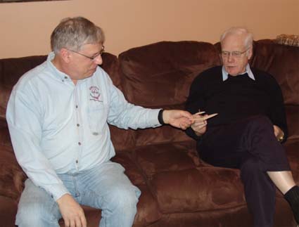
Roger Wilfong brought along several items to share. He showed a mini-catapult glider from Retro RC. Roger is also into model rocketry and plans to power another version with a tiny rocket motor.
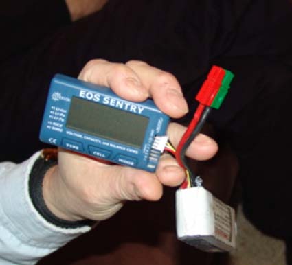
He demonstrated the use of his Hyperion EOS Sentry Battery Checker. He even showed how to measure the voltage of the popular single Li-Poly cell used for indoor flight. This is a very useful tool.
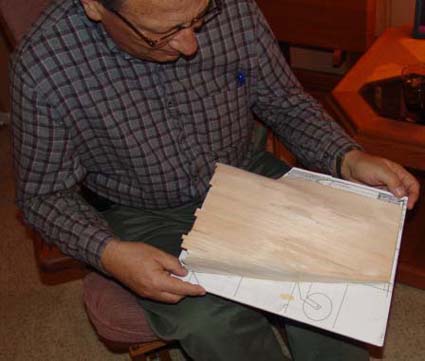
Rick Sawicki looks over Ken's An-2 tail model
Ken Myers shared the progress on his An-2. He'd never used planking for compound curves on fuselages and thought it was a good idea to once again practice the technique that he learned from Jim Young on RC Groups. "The Scale Builder's Workshop Video Tips -- July 2005 -- Planking Compound Curves" Ken also showed the video.
Jim is also an EFO member. Jim has a lot of great tips and videos on RC Groups, but you have to search carefully to find them. A good search term to start with is Scale Builders Workshop.
Ken noted that he's not very good at the technique and has planned on changing the planking from 1/16" to 3/32" balsa since the sheeting got too thin on his model.
Ken also shared a very funny video about when the beginner shows up at the flying field to learn how to fly using his 100 mph ducted fan. It is well worth the watch, especially if you've ever been an instructor!
Ken also showed his new Scorpion S-4035-250 (4963-250, 465g) that he purchased for the An-2 from AirCraft World in Japan, since there were none available here in the US. It came from Japan in six days with a shipping cost of only $6.88.
The meeting continued with refreshments and electric plane talk. It was a very nice evening!
Return to "What's In This Issue"
An-2 Progress from the Middle of January to the Middle of February
By Ken Myers
I continued to rework the plans based on the top wing area model I created. I reread Keith's article about building on the half-shell and crutch. The technique appears in "Building and Flying Electric Sport Scale" article. This is a great builder's resource. It is available in four linked Acrobat .pdf files on the EFO Web site. The downloads are found here: www.theampeer.org/sitetoc.html
The Scorpion S-4035-250 arrived on January 22 and I used it to input the motor dimensions into my 2-D CAD program.
I started working on the drawings for the built-up vertical stabilizer and rudder. I once again reread Keith's article and decided that a crutch build was not going to work, so I switched to the half-shell method.
I spent quite a bit of time on the Internet trying to find a solution to the tail wheel rudder linking. I decided that a control line elevator control horn should be used for the elevator. I continued working on the horizontal stabilizer design.
I thought that I might have a problem with the angled h-stab and rudder line and the rudder area that is in the vertical stabilizer. I made a Foamboard model to check that it would be okay.
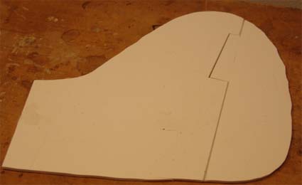
It worked fine.
On January 29 I had a major problem. CADintosh crashed and would not let me do anymore drawing! I spent a frustrating amount of time installing a newer version of the program. It also changed all my CADintosh files to the newer version, so I am stuck with it, even though the problems continue, including not being able to print 'tiles' of the plan to tape together for the full size plans!
I continued to work on the whole tail area design, with many, many revisions!
I thought that I could use the double-sided control arm from a DuBro tail wheel assembly for tail wheel and rudder hook up. I found that the scale position for the rudder control was going to work okay, as the servos would be located above the windows.
Rick Sawicki visited and brought a good selection of control line elevator control horns for me choose from and a Klett tail wheel assembly.
I decided to print the tail plans and build a model of the fuselage tail using Jim Young's planking video to learn the technique. That is when I found out that the program was NOT printing tiles correctly!
It took four days of working on and off to learn the tail planking technique. I changed the plans as necessary when I found errors.
On February 6, Keith called and we talked about the progress on the "Ant" and he gave me some invaluable guidance on the control system rudder/tail wheel hookup.
I found an article that showed how to hook up a "T" tail on a glider and I'll be using the method for the "Ant" tail.
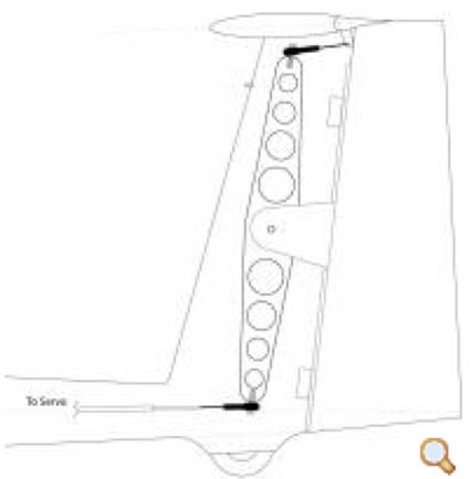
I ran into a pretty big oops on the plans. I realized that I had not reconciled the top and side views, which came from different 3-views. This took a lot of time to correct.
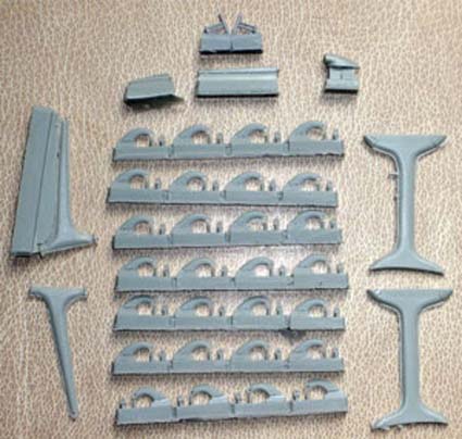
Shows tail strut, wing struts and hinges
During my Internet research I had found some photos of plastic models of the An-2. They showed the parts. I used the tail strut detail to get the correct shape for it. I made a .tif of the tail strut that could be under laid in the CAD program, drew it and size if for this model.
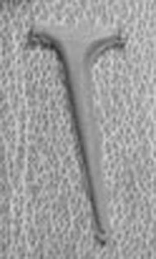
Image used in CAD program
I will be pressing on, even though my CADintosh program is still not printing 'tiles' correctly and I'm in constant contact with the developers, which is eating up a lot of time.
Right now it is time to get an order into Tower Hobbies for the ICE HV-60 ESC and other items while they have free shipping. (Made my $369 order on Feb. 16, arrived Feb. 18 - Free shipping!)
Return to "What's In This Issue"
Don Belfort's Nesmith Cougar Progress Update
From Don Belfort via email
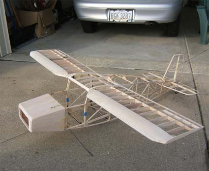
Hi Ken,
The Nesmith Cougar is coming along. We were out flying in -4F on Saturday morning (1/22/11). It made Sunday's 15F temperature seem warm.
Toledo is getting closer!
Don
Return to "What's In This Issue"
Spektrum Starts Hopping
By Ken Myers
Every morning I go through my email inboxes, RC Groups and RC Model Reviews. On the morning of Feb. 3 I noticed that RC Model Reviews posted "Good News: DSM starts hopping! HORIZON CATCHES UP".
You can learn more about this at Horizon Hobby's Web site.
I'm wondering if the X in DSMX stands for 10? Anyone know? I had predicted this would happen for a long time.
Thanks to Bob Aberle and Warren Plohr for keeping me in the loop on this one.
Return to "What's In This Issue"
Thanks for the February Ampeer
From John Jackson via email
Hi Ken,
Thanks for the newsletter - great as always! I enjoyed this issue more than usual for two reasons.
My first plane was a Leisure Playboy. I can still remember how the other club members treated it as a Novelty, and were offering condolences to my instructor for being "stuck with the electric guy" and having to make it fly. Well, it did fly but not that fast compared to the other gas planes of the day. I recall one day where the head wind pretty much matched my maximum speed, which made the plane stationary with respect to the runway.
Someone scrawled "No Parking" on the lid of a pizza box and stuck it on my pilot station. Interestingly, some of those hecklers now fancy themselves as 3D electric pilots. Their selective memory prevents them from recalling the "No Parking" incident from twenty years ago.
The second item of interest is the AN-2 article. A member of a nearby club passed away a while back and his widow held an estate sale. I bought a framed up AN-2 built from Don Luck's set of plans. I also got the plans and the original magazine. I plan to convert it to electric but have not started it yet - it is one of several items waiting for my attention in the workshop.
I am looking forward to future articles to see how you make out with your version!
Take care,
John Jackson
Russell, Ontario
Return to "What's In This Issue"
Some Good Advice on Trimming
From Frank Gue via email
Hi Ken,
I appreciate your sending me this material. Always something good.
I find that some - perhaps many - of our electric flyers have little or no free-flight background. Mine goes back to 1942, when I was Junior Champ in Edmonton, Alberta, with rubber power in the likes of the Korda Wakefield.
I have been designing and building models ever since and hold patents, as I may have told you. When designing, you must know the fundamentals of stability; when flying, you must know the fundamentals of trim, and the difference between stability and trim.
Most chaps fly ARFs these days. More than once I have watched a frustrated ARF-flyer trying desperately to correct a stalling or diving aircraft without knowing what he was doing, or perhaps relying on one of the several incorrect myths about trim.
With a new design, I always test-glide in high grass before applying power. If it is a really radical design, let's say a canard, I may build a model of the model, maybe one quarter size, from 1/16 sheet, as a glider, to get the CG position right.
With a proven design (an ARF) one should go through the procedure in the user manual or else the free-flighter's procedure to get CG right and trim right.
If you want a few hundred words article on this (much of which would start right out with the above), give me a shout. Word count and deadline.
Cheers,
Frank Gue
Burlington, ON
Look for Frank's helpful information on this topic in an upcoming Ampeer. KM
Return to "What's In This Issue"
Put This One On Your Event Schedule!
Keith Shaw Birthday Party Electric Fly-In
From Dave Grife grifesd@yahoo.com
The Balsa Butchers will once host the "Keith Shaw Birthday Party Electric Fly-In" at their field near Coldwater, MI. This is the 10th Anniversary of this event. The event will take place on June 4 and 5, 2011.
Contest Director: Dave Grife - E-mail:
grifesd@yahoo.com or Phone: 517.279.8445
Please e-mail or call with any questions
The Flying Field will be open Friday, June 3 for early arrivals
Saturday, June 4, hours are from 9 a.m. 'til 5 p.m.
Sunday, June 5, hours are form 9 a.m. 'til 3 p.m.
Landing Fee is $10 for the weekend.
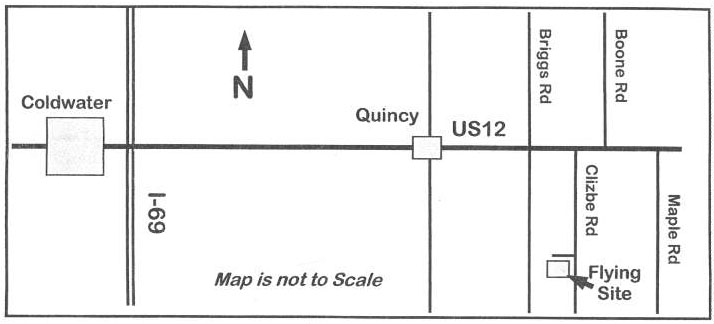
Directions: Quincy is approximately 4.5 miles east of I-69. Clizbe Road is approximately 1.6 miles east of Quincy. The Flying site is approximately 1.5 miles south of US-12 on the west side of Clizbe Road.


