 |
Flying High With Electric Power!
The Ampeer ON-LINE!
Fly the Future - Fly Electric! |
Site Table of Contents
| President: | Vice-President: | Secretary/Treasurer: |
| Ken Myers | Richard Utkan | Rick Sawicki |
| 1911 Bradshaw Ct. | 240 Cabinet | 5089 Ledgewood Ct. W. |
| Commerce Twp., MI 48390 | Milford, MI 48381 | Commerce Twp., MI 48382 |
| (248) 669-8124 | (248) 685-1705 | 248.685.7056 |
 | ||
| Board of Directors: | Board of Directors: | Ampeer Editor |
| David Stacer | Arthur Deane | Ken Myers |
| 16575 Brookland Blvd. | 21690 Bedford Dr. | 1911 Bradshaw Ct. |
| Northville, MI 48167 | Northville, MI 48167 | Commerce Twp., MI 48390 |
| 248.924.2324 | 248.348.2058 | 248.669.8124 |
| Mailed Ampeer printed subscriptions are no longer available.
The Ampeer is FREE on-line in Acrobat .pdf format and HTML with active links! | ||
| The Next Meeting:
Date: Saturday, May 24 Time: 10 a.m. Place: Midwest RC Society 7 Mi. Rd. Flying Field | ||
| What's In This Issue? | ||||
| Part 1: An Initial Safe Center of Gravity (ISCG);
Using the Mean Aerodynamic Chord (MAC) and Aerodynamic Center (AC) Ken Myers presents Part 1 of a two part article on finding the initial safe center of gravity. |
Upcoming Keith Shaw Birthday Party Electric Fly-in 2014 - Info and map for this upcoming event. | |||
| 30th Annual Mid-America Electric Flies 2014, links to the Flyer and map and hotel info for the 2014 Mid-Am. | ||||
|
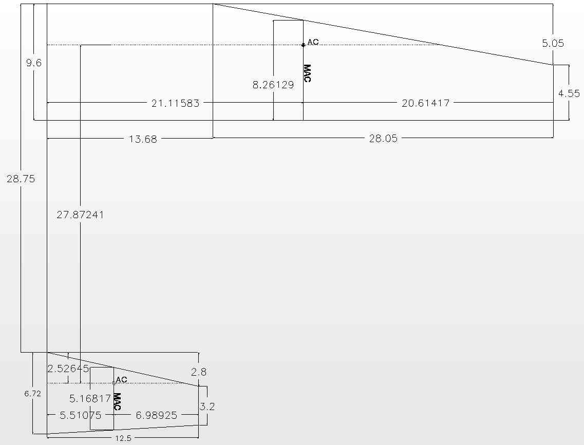
Using the Mean Aerodynamic Chord (MAC) and Aerodynamic Center (AC) By Ken Myers For decades, articles have been written in the aeromodeling press regarding the placement of the fore and aft, longitudinal, balance point. In aeromodeling, that position is almost universally called the center of gravity (CG), even though it is not the true center of gravity. The articles have generally coincided with calculating the location of the Aerodynamic Center (AC) of a wing's semispan as used in full-scale aircraft design. An initial safe center of gravity (ISCG) is required for a model to prevent the destruction of the model due to an undesirable pitching moment. This undesirable pitching moment can result in the model becoming unstable and uncontrollable in flight. The Aerodynamic Center (AC) is, "A point on a cross section of a wing through which the forces of drag and lift are acting and about which the pitching moment coefficient is practically constant." It appears that those statements, at least in part, are based on a research report by Walter Diehl for the Department of the Navy in 1942. He noted, "No mean chord has been found that is better than a simple average mean chord so located at the centroid of the semispan as to have its quarter-chord point coinciding with the geometrical average quarter-chord point for the semispan. This mean chord is converted to a mean aerodynamic chord by a simple fore-and-aft shift depending on the factors that affect the location of the aerodynamic center." Bold type was used by this author to emphasize Mr. Diehl's last sentence. It appears that that statement has been overlooked in all of the modeling press articles. Bold type is used by the author in other quotes to emphasize key words. The mean aerodynamic chord of any wing is defined by the Nomenclature of Aeronautics, Rep. No. 474, NACA, 1933 as, "The chord of an imaginary airfoil which would have force vectors throughout the flight range identical with those of the actual wing or wings." "In aeronautics, chord refers to the imaginary straight line joining the trailing edge and the center of curvature of the leading edge of the cross-section of an airfoil. The chord length is the distance between the trailing edge and the point on the leading edge where the chord intersects the leading edge." Flight testing is required to optimize the flight characteristics of the model airplane to the piloting skills and flight expectations of the pilot. Successful flight testing starts with an initial safe center of gravity (ISCG). "The pilot of an aircraft with positive longitudinal stability, whether it is a human pilot or an autopilot, has an easy task to fly the aircraft and maintain the desired pitch attitude which, in turn, makes it easy to control the speed, angle of attack and fuselage angle relative to the horizon. The pilot of an aircraft with negative longitudinal stability has a more difficult task to fly the aircraft. It will be necessary for the pilot to devote more effort, make more frequent inputs to the elevator control, and make larger inputs, in an attempt to maintain the desired pitch attitude. Most successful aircraft have positive longitudinal stability, providing the aircraft's center of gravity lies within the approved range. Some acrobatic and combat aircraft have low-positive or neutral stability to provide high maneuverability. Some advanced aircraft have a form of low-negative stability called relaxed stability to provide extra-high maneuverability." I received an email from David Plummer of Bellevue, WA, in October of 2013, regarding the initial safe center of gravity (ISCG) placement for his new Boeing Sea Ranger model. I'm having some difficulty determining the starting CG location for my 1/20 scale model of the Boeing Sea Ranger. I've used the 'calculator' available at adamone.rchomepage.com/cg2_calc.htm, but the diagram for the wing/stabilizer planforms in the calculator are not exactly that of the Ranger (see attached scan, which shows the location and length of the MAC based on data for the full scale aircraft; the other dimensions are for the as-built model). I've plugged in the values shown in the attached diagram; the 'calculator' comes up with a MAC very close to the correct (scaled) dimension, but it is located too near the aircraft/model centerline; this calculation also gives a CG that is too far aft (based on the data for the full-scale aircraft). Could you put me in touch with anyone (or another 'calculator') that can help resolve this confusion? (I'm tempted to located the starting CG close to the 26% MAC value for the full scale aircraft, but would like to get some sort of confirmation from a 'calculation'.) Any suggestions would be appreciated. 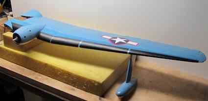 He also included a photo of the wing panel. His sketch was turned into a CAD drawing. |
|
There was a difference between David's drawing and the CAD drawing created from his sketch. He noted the distance from the root chord to the Mean Chord of the semispan, which he called the MAC, was 20.9" and the CAD drawing indicates 21.12". The numbers supplied by David were input into the online CG calculator that he referenced. |
|
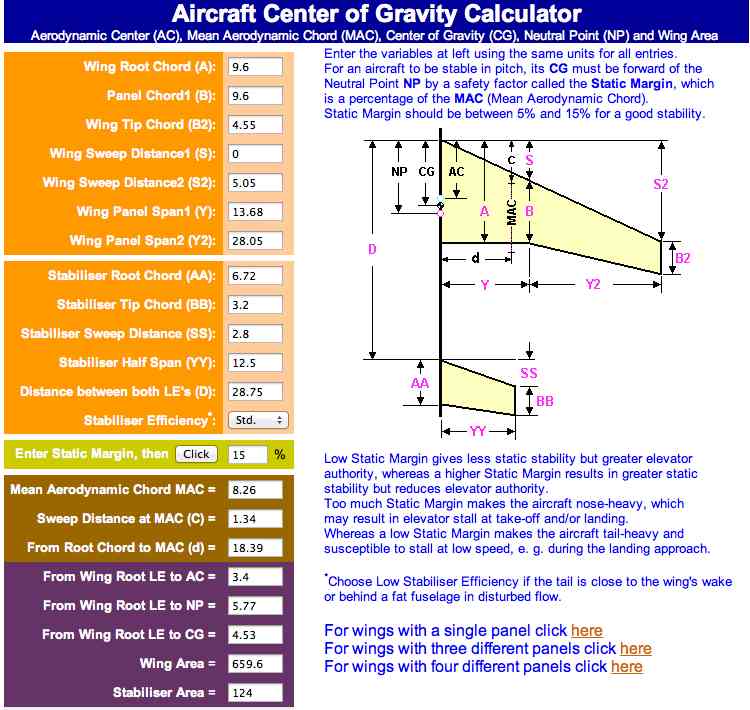
The online calculator showed the MAC as 8.26". That number coincided with the information provided by David. It calculated the distance from the root chord to the MAC as 18.39". The online calculator calculated the CG, using a static margin of 15% of the mean chord ahead of the neutral point (NP), as 4.53 inches from the wing Root Chord Leading Edge. "The static center of gravity margin (c.g. margin) or static margin is the distance between the center of gravity (or mass) and the neutral point. It is usually quoted as a percentage of the Mean Aerodynamic Chord." "Neutral Point (NP) is the point where the AERODYNAMIC FORCES generated by the wing and tail are balanced." "In order to achieve a good longitudinal stability, the CG should be ahead of the Neutral Point (NP), which is the Aerodynamic Centre of the whole aircraft. NP is the position through which all the net lift increments act for a change in angle of attack." The online calculator calculations placed the exemplary CG at about 38.7% of the MAC. Regarding a previous email between us, David also noted; I used the equations given by Van Putte and got a little different results than (I think) are given in your previous email, but I need to check all the arithmetic to see where/if my results actually differ. �As another cross-check on all this hay, I used the Excel-based spreadsheets developed by Curtis Suter (suterc@msn.com - not sure if this email is current); (www.tailwindgliders.com/Files.html - Sailplane Calc Cruciform Tail KM) It doesn't have the values for the Sea Ranger in it. When I plugged in all the values, it came up with a 'wing' MAC of 8.26, located 18.39 inches from the root; the CG (10% static margin, and 50% stab efficiency) came out at 3.66 inches aft of the root LE. So I guess I'll try a balance point at about 3.6 inches; this is probably close enough for this monster to start with. The distance from the root chord, 18.39", to the MAC provided by Mr. Suter's spreadsheet was the same as provided by the online calculator. |
|
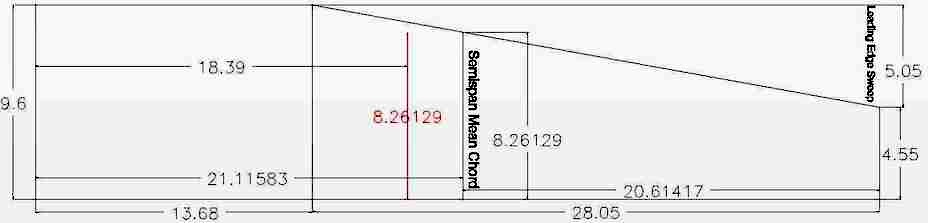
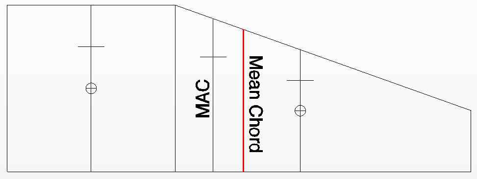
To transfer the semispan mean chord, or what was referenced as the MAC and its 1/4-chord position, the AC, to the wing of the physical model, it is necessary to have the correct distance from the root chord to the semispan mean chord, which was cited as the MAC in the previous examples. 18.39 inches does not appear to be correct distance from the semispan's root chord to the semispan's mean chord. Note were 18.39" from the root chord places the mean chord in the CAD drawing. Knowing the wings mean chord position in the semispan is not necessary for a rectangular shape.
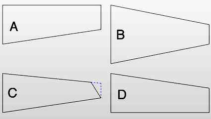
Figures A, B and D are trapezoids with the root chord and tip chord parallel. Figure C is not a trapezoid. Dashed lines were added to the top right of the 'tip side' of figure C to create a true trapezoid. No rounded wing tips are shown. According to Mr. Diehl, p. 414, "It is unnecessary to apply corrections for minor details in the wing planform such as fairings, fillets, or moderate radii at the wing tip." According to Mr. Diehl, figure C, with the small area added to create a trapezoid, is acceptable when the overall area is taken into consideration. Figures A, B and D could also include moderate radii wing tips that are not shown. The mean chord of a trapezoidal semispan can be mathematically calculated or determined graphically using a CAD program or on paper. |
|
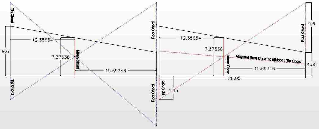
Ron Van Putte, in his "Radio Control Sport and Aerobatics" column in the December 1989 Model Aviation and Martin Irving in his column "Quiet Scale - CG Tips" in the April 2001 Electric Flight International showed a graphical method to locate the mean chord shown above. Jerry Nelson, in his article in the July 1995 Model Airplane News "How to: Center of Gravity Considerations", provided the solution on the right side of the graphic. Both methods yield the same result. Graphically, the mean chord of ONLY the tip panel of the Sea Ranger is 7.3753". Mr. Van Putte provided a formula for the mean chord of a trapezoidal area in his article.
From Stanford University:
For a trapezoid, the distance from the Root Chord to the Mean Chord equals:
A common way to express trapezoidal area using wing terms is:
When preforming these calculations using linear measures, it does't matter whether Imperial Units or Metric Units are used as long as they are not mixed. When chord, a linear measure, is multiplied by span, a linear measure, the result is square units. Besides its trapezoidal tip area, the Sea Ranger semispan also has a rectangular root panel. Only the mean chord for the tip panel has been illustrated thus far. Unfortunately, this author could find no good way to graphically illustrate the mean chord for the two combined panels of the semispan. It was calculated mathematically. Mr. Diehl provided a formula for the mean chord of several panels. Only two panels are illustrated here, but it can be any number of panels.
The mean chord of the root panel, since it is rectangular, is 9.6. The area for the rectangle is 9.6*13.68 or 131.328 square units. The area for the tip panel was previously determined to be 198.4538 square units. and its mean chord 7.3754. The Sea Ranger's semispan mean chord:
1/4 of the Mean Chord is 8.2613/4 = 2.065. Both the online calculator and Mr. Sutter's spreadsheet yielded an incorrect distance between the root chord and the semispan's mean chord compared to what is shown in drawing at the top of the page. It appears that they used the distance from the root chord to the mean chord formula that only works with a trapezoid. The full semispan of the Sea Ranger is 41.73".
The result of 18.38 appears very close to the incorrect number presented by the online calculator and Mr. Suter's spreadsheet. As previously noted, it is necessary to have the correct distance from the semispan's root chord to the semispan's mean chord to transfer the mean chord and it's 1/4-chord position to the physical model's wing, therefore it is necessary to have the correct distance as a result of the calculation. If a semispan consists of only one panel, the mean chord and MAC are located in that panel. For the vast majority of sport and scale models, with two or three panels in the semispan, the semispan's mean chord and MAC position is located in the second panel of a semispan. The Sea Ranger's mean chord of 8.2613 inches illustrates that. The 8.2613 mean chord is less than the 9.6 tip chord of the root panel and greater than the 4.55 chord of the tip chord. Therefore, the semispan's mean chord must lie in the second panel. The formula for the distance from the 2nd panel tip chord to the mean chord is:
Slope describes how 'steep' a straight line is from horizontal. It is often used to describe the pitch of a roof or the rise of a stairway. 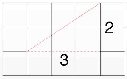 The illustrated slope is 2/3 (read as 2 over 3) or the decimal 0.66667. That means that for every 3 units the line moves horizontally away from its point of origin, it rises 2 units. To simplify the the math, a spreadsheet is available to do the slope calculations, as well as all of the calculations in this article. To use the spreadsheet to calculate the model's semispan mean chord for the wing and horizontal stabilizer, the modeler must input the leading edge sweep of a single panel semispan or the leading edge sweep of the second panel for a two or three panel span. The leading edge sweep is the linear measure from a horizontal line originating at the leading edge of the root chord and measured between that line and the leading edge of the tip panel. Previous diagrams show the leading edge sweep of the Sea Ranger's 2nd panel as 5.05 inches. The half slope for the 2nd panel of the Sea Ranger, calculated using the spreadsheet, is 0.090018.
The distance from the semispan's root chord to the mean chord equals the span of the root panel plus the span of the 2nd panel, the total semispan span, minus the 2nd panel tip chord distance to the mean chord. For the Sea Ranger that is 41.73-20.6142=21.1158 inches from the root chord. That is the correct distance from the root chord to the mean chord. There are several modeler inputs required for use of the spreadsheet to calculate an ISCG. The inputs can be measured on the actual model, plan or a 3-view. The spreadsheet is set up to take inputs for up to three panels for both the semispan of the wing and semispan of the horizontal stabilizer. In the majority of instances, the horizontal stabilizer will have only one panel in its semispan. One of the required inputs is the distance from the leading edge of the wing root chord to the leading edge of the horizontal stabilizer root chord leading edge. Each panel in the wing and horizontal stabilizer semispans require; root chord, tip chord, leading edge sweep and span measurements. 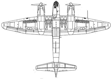 It should be noted that for some wing planforms the root panel's tip chord is NOT always the same length as the root chord for the 2nd panel. The Ju-88's root panel tip chord is longer than the root chord of the 2nd panel. Also note that the wing of the Ju-88 contains three panels. 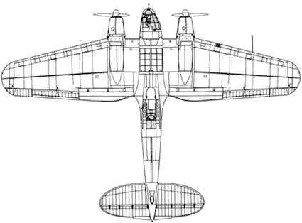 Another instance of the root panel tip chord and 2nd panel root chord not being equal is the Heinkel H.111. It has a 2nd panel root chord that is longer than the root panel's tip chord. The Sea Ranger's measurements illustrate the measurements to obtain from the model. Distance Leading Edge Wing Root Chord to Leading Edge Horizontal Stabilizer Root Chord: 28.75" Wing:
Horizontal Stabilizer
Jerry Nelson stated in his article, "Where should a model's CG be? There's no exact point, but as a rule of thumb, placing it at 25 to 30 percent of the wing's mean aerodynamic chord (MAC) will generally allow stable flight." Mr. Nelson's percentages are typical for most articles regarding CG placement. Some authors note 33% of the MAC as the rearward position of the range. Roy Day, in his article "Get the CG Right" in the September 1998 Model Airplane News, suggested using the Aerodynamic Center (AC) as the location of the CG. The AC location being one fourth, or 25%, of the MAC. Several aeromodeling authors have shared formulas for locating the CG mathematically using the MAC as a reference 'line'. Martin Irving, in his previously noted article, shared a CG formula from Gordon Whitehead's Radio Control Scale Aircraft - Models for Everyday Flying. Whitehead's formula:
The spreadsheet was used to calculate the Sea Ranger's tail moment using the distance between the 1/4-chord location on the mean chord of the wing and 1/4-chord location on the mean chord of the horizontal stabilizer. The distance was calculated as 27.87 inches. The wing area of the Sea Ranger is 659.5635 sq.in. and horizontal stabilizer area is 124 sq.in.
Mr. Irving noted that he had a problem with the CG as calculated by this formula. He said, in regards to a Japanese 'Judy' bomber he was discussing, "I must confess that I would start a little ahead of this ('this' referring to 4.7" for the Judy under discussion KM), perhaps 4" from the leading edge but plan to move it back with the motor pack." Mr. Irving didn't make it clear as to whether he meant 4" from the leading edge of the mean chord or the root chord. If he meant the mean chord, that would have placed the CG at 11.875 (Mr. Irving's calculated mean chord KM)/4. That is 33.68% of the mean chord. Ron Van Putte provided another CG formula in his article.
The three formulas used to locate the CG, including the online calculator, for the Sea Ranger all placed the CG rearward of 33% of the wing's semispan mean chord. Since the CG formulas presented in the aeromodeling press and online appear to be from 'reliable' sources, what is the problem? Is there really even a problem? Maybe the mean chord is not the Aerodynamic Mean Chord, MAC. While using the semispan's mean chord makes sense, it doesn't follow what Mr. Diehl's research noted. If the semispan's mean chord is used as the MAC, an essential part of Mr. Diehl's statement is ignored. |
|
Above is a CAD drawing of the illustration found on p. 417 of Mr. Diehl's report. Again, "This mean chord is converted to a mean aerodynamic chord by a simple fore-and-aft shift depending on the factors that affect the location of the aerodynamic center." The calculated semispan mean chord of the two panels was added by the author to Mr. Diehl's illustration and is shown in red. Note that the average mean chord of the semispan is NOT the MAC, according to Mr. Diehl. What happened? What happened? That will be explained in Part 2 in the June 2014 Ampeer. Upcoming Keith Shaw Birthday Party Electric Fly-in 2014 The Balsa Butchers will once again be hosting the "Keith Shaw Birthday Party Electric Fly-In" at their field near Coldwater, MI. The event will take place on May 31 and June 1, 2014. Contest Director: Dave Grife - E-mail: grifesd@yahoo.com or Phone: 517.279.8445
The Flying Field will be open Friday, May 30 for early arrivals Saturday, May 31, hours are from 9 a.m. 'til 5 p.m.
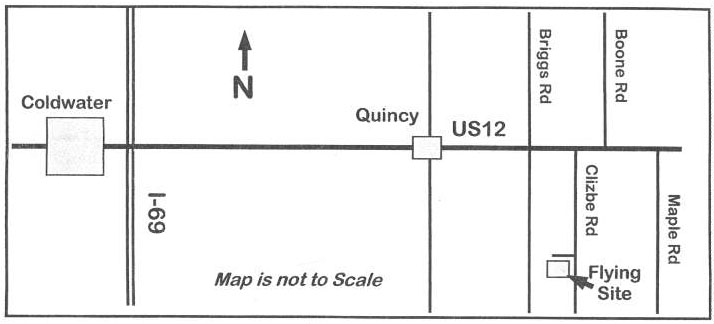
Landing Fee is $15 for the weekend. Directions: Quincy is approximately 4.5 miles east of I-69. Clizbe Road is approximately 1.6 miles east of Quincy. The Flying site is approximately 1.5 miles south of US-12 on the west side of Clizbe Road. |
|
30th Annual Mid-America Electric Flies 2014 Saturday, July 12 & Sunday, July 13
Announcing the 30th Annual Mid-America Electric Flies Saturday, July 12 & Sunday, July 13
Here are the links to the 2014 Flyer as well as the field map and local area hotels list. 2014 Map to the flying field and local hotels listing |
To Reach Ken Myers, you can land mail to the address at the top of the page. My E-mail address is: KMyersEFO@theampeer.org