 |
Flying High With Electric Power!
The Ampeer ON-LINE!
Fly the Future - Fly Electric! |
Site Table of Contents
| President: | Vice-President: | Secretary/Treasurer: |
| Ken Myers | Richard Utkan | Rick Sawicki |
| 1911 Bradshaw Ct. | 240 Cabinet | 5089 Ledgewood Ct. W. |
| Commerce Twp., MI 48390 | Milford, MI 48381 | Commerce Twp., MI 48382 |
| (248) 669-8124 | (248) 685-1705 | 248.685.7056 |
 | ||
| Board of Directors: | Board of Directors: | Ampeer Editor |
| David Stacer | Arthur Deane | Ken Myers |
| 16575 Brooklane Blvd. | 21690 Bedford Dr. | 1911 Bradshaw Ct. |
| Northville, MI 48167 | Northville, MI 48167 | Commerce Twp., MI 48390 |
| 248.924.2324 | 248.348.2058 | 248.669.8124 |
| Mailed Ampeer printed subscriptions are no longer available.
The Ampeer is FREE on-line in Acrobat .pdf format and HTML with active links! | ||
| The Next Meeting:
Date: Saturday, May 2 Time: 10 a.m. Place: Midwest RC Society 7 Mile Rd. Flying Field | ||
| What's In This Issue? | ||||
| New North American Supplier for A123 Systems 2500mAh Cells Ken Myers shares information on the new North American supplier for 2500mAh A123 System cells. | Reminder About EFO Flying Season Meetings Ken shares that EFO Flying meeting dates are tentative. | |||
| Upcoming Keith Shaw Birthday Party Electric Fly-in 2015 - Info and map for this upcoming event. | The March EFO Meeting Highlights from the March EFO meeting | |||
| Turnigy 2 in 1 Power Meter/Servo Meter 1.5 TFT Review Ken reviews this inexpensive meter from Hobby King. | Installing a 3S "A123" 2300mAh LiFePO4 battery into a Flyzone Sensei Ken explains the modifications to use a 3S A123 pack in the Sensei trainer from Hobbico. | |||
| All About Tactic Radio Systems An announcement of a local seminar on the Tactic Radio Systems. | 31st Annual Mid-America Electric Flies 2015, info and links to the flyer and hotels and field map. | |||
|
By Ken Myers I received the following email from A123 Systems. Good Day, Please see the attached letter for information regarding A123 Systems' newest North American distributor, StorTronics Thank you for your continued support,
Here is the letter that was the attachment to the above email. March 6, 2015
A123 Systems is pleased to announce StorTronics® as our newest authorized North American Distributor to help our customers design and develop battery systems and get them to your door. In an effort to provide our customers with the best possible solution to getting your product delivered quickly and efficiently, we have established a strategic partnership with StorTronics® and consider this trusted relationship a key channel for supplying our quality product, with exceptional service. A123's Value Add Channel Partner Program (VACP) connects customers to approved strategic partners who have the knowledge and technical capabilities that are required to design and integrate advanced solutions using A123 technology. StorTronics® understands the technical aspects of the products and their applications and helps provide customers with solutions to their energy needs. StorTronics® was founded in 1981 and is located in Livonia, Michigan. For more information and orders, please visit www.stortronics.com or www.a123batteries.com or via the following contact information:
A123 Systems and StorTronics� look forward to servicing all of your battery and energy storage needs. Sincerely,
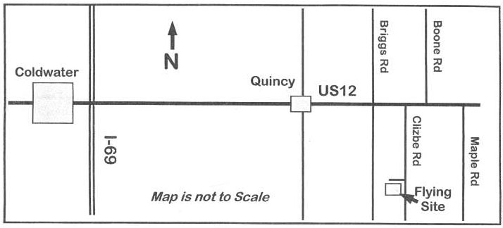
Reminder About EFO Flying Season Meetings Dates given for the flying season EFO flying meetings are tentative. The date depends on the weather and may change from the one noted in the monthly Ampeer. The EFO Web site has the most current information posted. Also, emails are sent to EFO members if a date change is required. Upcoming Keith Shaw Birthday Party Electric Fly-in 2015 The Balsa Butchers will once again be hosting the "Keith Shaw Birthday Party Electric Fly-In" at their field near Coldwater, MI. The event will take place on June 6 and June 7, 2015. Contest Director: Dave Grife - E-mail: grifesd@yahoo.com or Phone: 517.279.8445
The Flying Field will be open Friday, June 5 for early arrivals. Saturday, June 6, hours are from 9 a.m. 'til 4 p.m.
Landing Fee is $15 for the weekend. Directions: Quincy is approximately 4.5 miles east of I-69. Clizbe Road is approximately 1.6 miles east of Quincy. The Flying site is approximately 1.5 miles south of US-12 on the west side of Clizbe Road. |
|
The monthly EFO meeting was held at Ken Myers' house. There were a lot of new projects shared. Mark Rittinger joined us and shared two of his latest creations. The first was his new Omen III, which is featured in Model Airplane News. It is a slightly reduced version of the Omen II classic pattern plane. 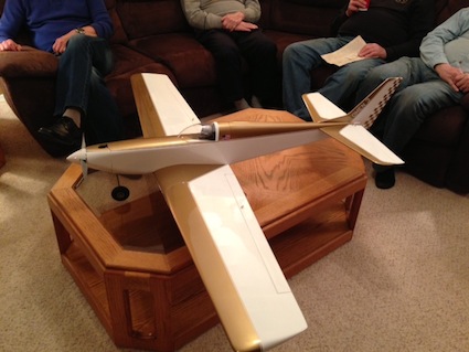 It is a real beauty. Mark put it on display at this year's Toledo RC Expo The RC Groups thread on this plane is here.
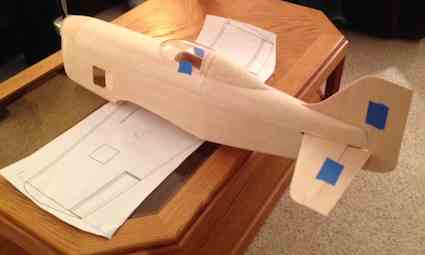 His second plane, which was still under construction, is the Lowers-Minges LM-1. Full scale homebuilt racer had about a 16.5 foot span. It was to be powered by a Ranger V770 V12 500 horsepower engine. Unfortunately (Maybe KM) it was never built. The only reference that Mark could find on this plane was a drawing from a 1974 Flying magazine. When Mark showed it at the meeting, he sat the fuselage on the full-size wing plans. The wing had not been built yet.
His RC Groups build thread is here. 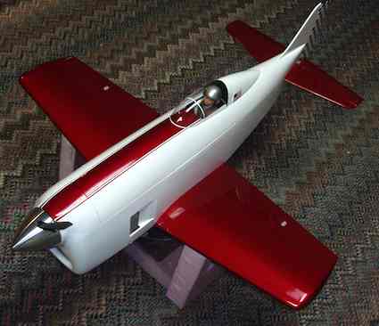 The updated photo is from his RC Groups thread. It has a very small wing for its size. The span is only 33" and it has 297 sq.in. of wing area. 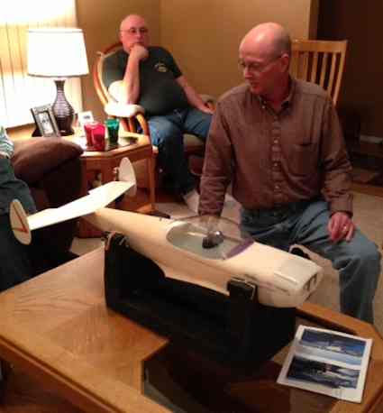 Denny Sumner shared his still under construction 63" Jack Stafford Alon Aircoupe. It has been a very challenging build, to say the least. Denny's build thread on RC Groups is here. Denny is in the final stages of painting the fuselage, as the weather permits. Hopefully it will be done soon, weather permitting.  Charlie Dochenetz shared his newly completed "Midwest Sweet Stik". It was built from the Lazer Works short kit. It uses the Midwest Models Kit Plans and has a 54" span. It uses a Rimfire outrunner motor and a 4S A123 pack. Jim Young brought along his prototype Monocoupe 90A. This will soon be a T&J Models' kit. The model has a wing span of 55" and for power he's targeting a 30mm outrunner using a 3S 3300mAh pack. His build thread is on RC Groups is here. Robert Throne is also building one of Jim's prototypes. He brought along his partially constructed fuselage to discuss some possible changes to the construction and compare their two models. 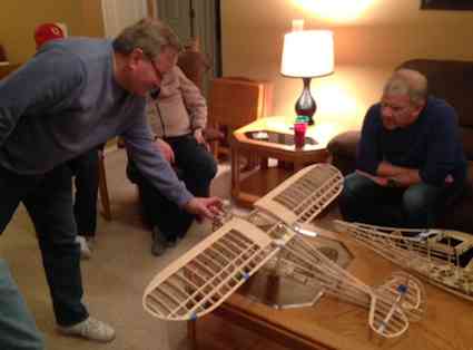 Jim points out some of the features of his design. Robert Throne, on the couch, listens to some of Jim's pointers. Robert's fuselage is also shown in the photo. Ken Myers demonstrated his new, unimpressive, Turnigy 2 in 1 meter from Hobby King. It was a great evening of sharing and the final photo shows what we do best, share great tips and tricks. 
Turnigy 2 in 1 Power Meter/Servo Meter 1.5 TFT Review
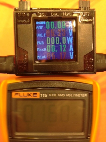
While looking for a power meter with a phase tachometer option, similar to the discontinued Hyperion Emeter II and the Eagle Tree eLogger, I saw the Turnigy 2 in 1 Power Meter/Servo Meter for the first time. It DOES NOT have a phase tachometer available, but it looked interesting. It is a power system power meter and it can also be used to check the amp draw of the servos of an onboard radio system. I downloaded the instructions from the Internet. I watched all of the available videos about it online. None of the videos, not even Hobby King's, showed how to use the servo radio system amp draw check correctly. The unit arrived in the mail on Monday, March 9. It does not come with any connectors on the power leads. The tinned lead ends were clipped off and then Anderson Power Poles were crimped onto the leads. The meter was hooked up to a 6S A123 2300mAh pack. When the meter came on, it was on CH1 (Channel 1), which is the low power reading and no reading was shown. To change to CH2, the watt meter readings for power systems, the Nxt. (Next) button was pushed. It took several tries to get the push the button to work with my finger. The button is flush with the top of the unit. I decided to use a wooden toothpick to press the buttons. It works okay, but it is still �iffy� when the toothpick is used. There are two other buttons on the top of the unit besides the Nxt., they are Inc. (Increment) and Dec. (Decrement). The unit always initializes on CH1. The menu is linear. Each time the Nxt. button is pressed it goes to the next menu, followed by each item in all of the menus starting with CH1 and then CH2. A press of either the Inc. or Dec. buttons brings up a pretty useless graph of the amps with the running time. After two days of comparing the CH2 watt meter to a Fluke Model #117 multimeter and my Emeter II calibrated using the multimeter, I found the voltage reading difference of the 2 in 1 meter to be inconsequential, about 0.5%. The amp readings for the 2 in 1 ended up being greater than 3% higher than the other meters, on average. The 2 in 1 DOES NOT SHOW watts in, therefore the highest amp reading on the 2 in 1 meter need to be multiplied by the lowest voltage recorded. Example:
The CH2 watt meter is close enough to check a power system for 'safe' operation, but not good enough for accurate testing of motor and prop combinations to enter into a program such as Drive Calculator. Always having to press the button to get to CH2 for taking watt meter readings is a bit of pain when doing a lot of testing. Having to run through all of the menus to get to the one you want gets a bit tedious as well. The lowest the CH2 watt meter can be set to, without showing a warning, which covers the bottom 1/2 of the display, is only be 8 volts. This makes taking watt meter readings with a 2S LiPo pack difficult as the warning won't go away until the pack has recovered to at least 8 volts. The main purpose of CH1, the onboard radio system load meter, is to measure and record the maximum amps and minimum volts drawn by the onboard radio system. CH1 could also be used to measure 'low' power systems. My unit came with a lead that, at first glance, looked like a Futaba type connector with the guide on the side to plug into the top, right of the meter. On the other end of the lead is a JR type connector, which is also known as a Hitec "S" type or universal type servo connector to plug into any open channel in the receiver of the onboard system to be tested. Thanks to Jacob Hendrickson's input, I found the supplied lead not wired in the usual manner. The signal and negative leads are reversed from 'normal' on both connectors with the negative and signal wires switched. 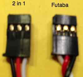
 For the bench test, a 4.8V receiver pack was plugged into the top, left connector of the 2 in 1 meter. Another servo lead, with the negative wire cut, was also inserted in the lead going to the receiver. A Fluke multimeter, set to amps, was used to complete the circuit and measure the amp draw. The leads were plugged into a Tactic TR624 receiver with a Hitec HS-225 plugged into the aileron socket and a Hitec HS-85MG plugged into the elevator socket of the receiver. The voltage shown on the 2 in 1 meter matched the voltage shown on the Fluke multimeter. On average, under test, with the Fluke multimeter inline, the 2 in 1 measured a maximum amp draw of 0.16 amps when an aileron servo and elevator servo were moved at the same time by pulling slowly back diagonally on the transmitter stick. The Fluke showed 0.18 amps. The test was repeated many times and the results were similar. That is about a 10% difference. One thing I was not expecting to see was when the transmitter stick was just released and allowed to return to center by the spring tension, the Fluke maximum amps almost doubled what was seen when the stick was allowed to center very slowly. This 'big' amp jump was not recorded as maximum amps on the 2 in 1 meter. I believe the 2 in 1 doesn't 'sample' fast enough to notice this almost instantaneous increase in the amp draw. The Fluke also showed an 'idle current' of 0.052 amps, but the 2 in 1 didn't show the 'idle current' at all. The real value of the 2 in 1 meter is to send it up in a plane and let it register the maximum amps drawn by the radio system during an actual flight. The 2 in 1 meter weighs 46.1 grams or 1.63 oz. Any decent size plane should be able to carry the additional weight. It will also record the lowest voltage. These are useful numbers to know when using a battery eliminator circuit (BEC) to power the onboard radio system. The photos show just some of the many varying amp results from CH1 when checking the onboard system draw. 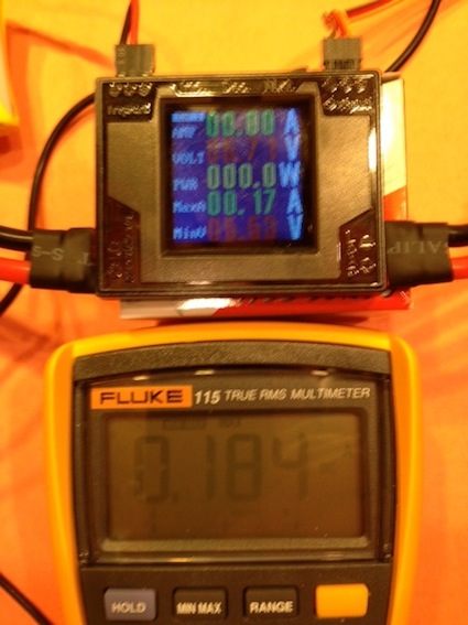
 Installing a 3S "A123" 2300mAh LiFePO4 battery into a Flyzone Sensei
The April 2015 Ampeer contains the review of the stock version of the plane. The following describes how I changed to an A123 3S "A123" battery. The supplied ESC was tried with a 3S "A123" battery and did not work well with the battery. The ESC was replaced with a Castle Creations Thunderbird 54, which was on hand. 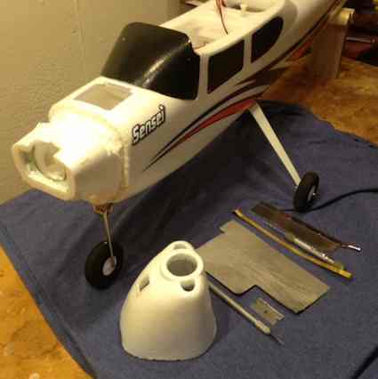 I did not want to purchase a new cowl, so I did not follow the method in the tech bulletin for the cowl removal. Using the tools pictured in the photo and with a lot of patients and prying, the cowl was removed from the fuselage. 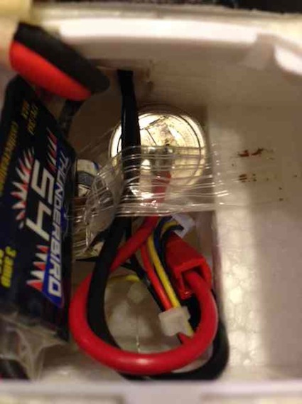 Two cells were positioned in the battery compartment and a third cell was hook-and-loop fastened and secured with strapping tape to the former just to the rear of the battery compartment after the battery was constructed. 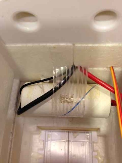 The battery was built outside the airframe with the appropriate wiring and balance connector and then slid into place and secured with strapping tape. The Thunderbird 54 was placed in the same position as the original ESC. The lead on the Thunderbird 54 was just long enough to reach the Tactic TR624 receiver. Before I reattached the cowl, I weighed it. With the five large weights in it, it weighed 69g/2.43 oz. 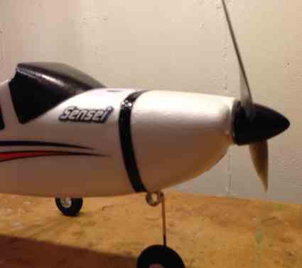 The cowl was attached using a 1/2" strip of TopFlite Econokote. Econokote is a relatively low temperature covering film and there was no problem ironing it onto the foam with a setting between low and medium on my covering iron. Because of the "A123" cell's lower voltage, to get the watts in back up to the equivalent 3S LiPo input, a larger prop was used.
Please keep in mind that the stock motor. with a 3S LiPo battery, provides plenty of power. The following changes were made as the result of my choosing to use a 3S "A123" 2300mAh battery. I used the plane as a trainer with an APC 11x7E and an APC 12x6E. When I first used it, I found the takeoff run long, but acceptable with just over 200 watts in. On August 2, 2014 we had a very hot and humid day. That weather condition changed the density altitude significantly and the takeoff run was very long! In the air, the plane was fine for training, but it would have been hard for a student pilot to do the very long takeoff run and know when to lift off. I considered adding a fourth "A123" 2300mAh cell. That modification would have required another change in ESC and reconfiguring the custom pack with a fourth cell. I decided to 'remotor' the plane using an O.S. Motor OMA-3820-1200. The motor change required some major surgery to the front end of the plane to install a new firewall. Luckily, I already had created a removable cowl. Before the reconstruction of the front end began, I replaced the double sided sticky tape on the Tactic TR624 receiver with VelcroTM. I kept finding the receiver loose and just 'floating' in the plane. I also straightened the right main landing gear leg. I was very surprised to find it 'bent' a little. It had looked quite stout, but it seems that my student pilot managed to 'bang' and bend and twist it a little. All of the angles and distances were measured for the new motor mount using the stock motor as reference. Part of the foam sticking out for the motor mount was removed and a 3/16" birch plywood firewall was created. After checking and double checking the fit of the new firewall and motor, the new firewall was 30-minute epoxied to the remainder of the original foam motor extension. 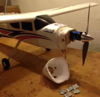 Once the epoxy cured, an E-flite 1.75" Aluminum Spinner and an APC 10x7E prop were affixed to the 158g 1250Kv OS motor. The balance was checked using the original reference position and found to be good. I replaced the stock spinner with the E-flite because the stock spinner screws had 'stripped' their holes in the spinner backplate and no longer held the spinner securely to the backplate. With the new motor, the 61 grams of nose weight were removed from the cowl, as they were no longer needed. The new power system, consisting of the custom 3S "A123" 2300mAh battery, Castle Creations Thunderbird 54 and the new O.S. motor, was checked for power. The Emeter II showed; 8.49V, 34.2A, 290 watts in and 9085 RPM. That RPM yields a pitch speed of about 60 mph. While waiting for the epoxy to cure, I weighed and determined the Kv of the stock motor. It weighed 72.3g. The measured Kv, using the drill press method, was 1268. A similar motor, that I found in Drive Calculator, the HiModel A2217K-8 (70g 1259Kv), predicted similar results to the data previously recorded using a 3S LiPo battery with the stock motor and stock 10x5 prop. Drive Calculator showed an efficiency of approximately 62% for the HiModel motor. That is about 186 watts OUT with about 300 watts in. That is pretty typical for these small brushless motors. Make no mistake, the stock power system, using a 3S LiPo, works well in this application! The problem with trying to use a 3S A123 pack with the stock motor was that it was only putting in a bit over 220 watts, even with the higher amp draw. Using the higher amp draw put the motor in about the 55% efficiency range. That yielded only about 120 watts OUT, hence the very long takeoff runs. That was about 60 watts OUT below the stock power system. Replacing the motor allowed me to get approximately 300 watts in when using the 3S "A123" 2300mAh pack. With approximately the same power in as the stock power system Drive Calculator predicted about 79% efficiency for the O.S. motor using an APC 10x7E prop. Drive Calculator Prediction: 8.55V (that is my standard constant voltage for a 3S "A123" pack at a predicted 35 amps), 33.8A, 289 watts in, and 8905 RPM. Drive calculator showed approximately 230 watts OUT. I got almost 44 watts OUT for free, just by changing to a more efficient motor compared to the stock setup. The estimated RPM yielded a pitch speed of about 59 mph. The performance increase looked good on paper. After doing the power system data capture, it also looked good on the Emeter II. My students have no problem getting it off the ground now. It really is a great trainer, either in the stock form or with the motor and battery change! All About Tactic Radio Systems, A Local Seminar
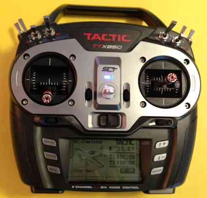
On April 25 at 11 a.m., Flightline Hobby, 1192 S. Lapeer Rd., Lake Orion, MI, is sponsoring a seminar called, "All About Tactic Radio Systems". Joe has is the presenter and he will be assisted by Ken Myers. Tactic transmitters, receivers, servos and Tx-R ready planes will be discussed. 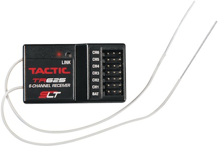 31st Annual Mid-America Electric Flies 2015 Saturday, July 11 & Sunday, July 12
|
To Reach Ken Myers, you can land mail to the address at the top of the page. My E-mail address is: KMyersEFO@theampeer.org