|
Important Notice!
You can contact Bob Kopski regarding the BDM information in the October Ampeer at kopskib@gmail.com. I would appreciate a CC when you do - Ken
Ke variation
From Tom Cimato MaxCim Motors
Hi Ken,
I read your article about the Scorpion motor Ke. (August 2010 Ampeer KM)
It is considered normal for the published Ke to have a tolerance of +/-10%. In your case that would mean that the published 710rpm/v would have an upper limit of 710 +71 = 781rpm/v. So, your measured 779 value is within acceptable limits.
It is unreasonable to expect no variation. We spec +/-10% in industry/aerospace and see about +/-5% average lot to lot variance.
The variation comes from the variance in charge of the magnets, which is usually within +/-10%.
A winding error may also cause a variance in Ke, but I wouldn't expect that from a commercially produced motor. Ke is directly proportional to the number of turns/coil.
Of course as usual there are many more things that we could discuss about motor variation.
Hope this helps.
Cheers,
Tom
Thanks very much for your valuable and extremely knowledgeable input Tom. It is very much appreciated. KM
Return to "What's In This Issue"
Learning from the Ampeer
From Scott McKie scotsman7@comcast.net
Ken,
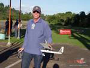
The Super Stearman is a beauty. www.rcgroups.com/forums/showthread.php?t=1222582
I didn't get out today but I had a couple of great early morning flights with my Great Planes ElectriCub (the 58" wing span version) yesterday morning. I've been working on the sideslip and am slowly starting to get it.
I've also been flying a 1/2A Herr Pitts Special that I built and converted to electric power last year. What a fun little "hot-rod"!
www.rcgroups.com/forums/member.php?u=198047
I've learned a lot from the Ampeer over the past couple of years since I got back into the hobby. My whole fleet is electric now whereas when I used to fly in the mid-80's it was all K&B 40 powered!
Keep up the great work and thanks for doing what you do!
Scott
Return to "What's In This Issue"
Using an Inline Fuse for Free Flight Electrics with Brushed Motors
From John Riese jriese@hotmail.com
Hi Ken,
I enjoy reading your on line newsletter each month. You have lots of technical stuff that takes the mystery out of electric flight. Here is something you might be able to use.
I have a Ztron timer for free flight. The timer is not like the "discharge a capacitor to control the gate of a MOSFET" simple ones that are used in small indoor and E36 planes. It actually sends a varying pulse width to an R/C speed control to vary the motor speed. The timer is programmable by dipswitches to control the motor run time but also the power output by simulating a receiver pulse output. It also has an output for a DT servo.
I was using a 2 cell LiPo of 950mAh to drive an old ferrite Astro 020 motor, which originally ran off 4 Nicads. Since I could control the power output, the 7.4 volts from the battery could be reduced to a nominal 4 or 5 volts effective and keep the motor current down. The average current was only about 5 amps or so. Since the battery capacity was much higher than the original 250mAh of the Nicads I was able to obtain many 20 second motor runs on one charge.
This worked well until the voltage started to drop. The plane lost altitude and landed with the motor still running at a slow rate well before the expected end of the motor run time. Of course the plane nosed over and stalled the motor. The current and voltage into the motor as seen by the Astro Whattmeter is of course an average of the on/off pulses sent to the motor. During the on portion of the duty cycle I�m sure the current exceeded the speed control 20 amp rating.
Let�s cut to the chase. I thought an in line fuse would be useful. Harbor Freight has a kit for $4.99 that contains twelve in line fuses holders for the automotive plastic ATC fuses. One just cuts the wire from the battery and crimps on the holder with a pair of pliers. They have red ones for 18-22 ga. wire and the blue ones are for 14-16 ga.
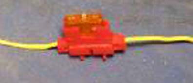
I was concerned about the possible extra resistance and power loss so ran some tests using a current limited power supply and digital meter. First I took a piece of 18-gauge wire and measured the voltage drop at various currents to determine the initial resistance. Then I cut the wire and spliced in the fuse holder, in this case the red one for smaller wires. I measured the voltage drop across the wire and fuse combination and calculated the new resistance. Then I subtracted the initial resistance of the wire to get the new value for the fuse. I also checked to see how much current the fuse would take before it blew.
The results were encouraging. I measured a 3, a 5 and a 20-amp fuse. The 3 amp and 5 amp fuses would handle a 20 percent over current indefinitely. As I increased the current limit on the power supply to over the 120 percent value the fuses blew immediately. I would call them fast blow and think they could protect a speed control if sized to just over the maximum current expected by a running motor with a fully charged battery.
The fuses are available in a number of useful values like 5, 7.5, 10, 15, 20 and 30 amps everywhere. One doesn�t have to order from an electronics parts supplier.
The resistance of the 3-amp fuse was 39 milliohms, the 5 was 26 milliohms and the 20-amp fuse had 6 milliohms resistance. This calculates out to a power loss of .35, .26 and 2.6 watts at the maximum rated current of the fuses. I think this can be tolerated in most planes. The weight was only 3.7 grams for the fuse and holder.
The fuses were hard to insert and remove from the holder. I think the higher contact pressure made for a low resistance between the fuse and holder, which would explain the tiny value of power loss. The fit was too tight to enable the fuses to be used as an arming switch. I think the Anderson Powerpole/ Sermos looped back wire type is much more practical. However the fuse would be a great safety feature and could be buried in the planes innards, as it would not normally be accessed.
What do you think of the idea?
John in Kalifornia
Sound like a good idea to me and great reminder that electric flight is NOT just RC and outrunners! KM
Return to "What's In This Issue"
A Micro Flyer from Brazil
From Paulo Scheidegger pauloscheidegger@terra.com.br
Hi Ken,
Thanks for your continued great job with the Ampeer! I loved the stuff about glow to electric comparison. This kind of basic information is all I wanted to know some years ago when my first experiences with electrics took place. Right now it will be very useful in converting the glow kits we find in Brazil.
These days I am getting lots of fun from a micro flyer, with an amazing 1.8 watts input power. Obviously it can only fly in no wind conditions, but the folks at the club always stop to watch it cruise at a walking pace... I found it would be equivalent to a .001 cu.in or about 1/10th of a Cox .010!
Best regards,
Paulo
Return to "What's In This Issue"
BEWARE OF THE YELLOW AND BLACK SUNBURST "LEGACY"
From Rick Sawicki rrrjjjsss@aol.com
I received the following information on this beautiful control line stunter from Rick Sawicki way back in July. It has since flown many very successful flights! KM
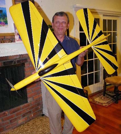
The Legacy, electric control line stunter it is finally finished. I started it back on back in February. A few things like vacation trips to San Diego, Peru and the Amazon unfortunately interrupted the progress!!!
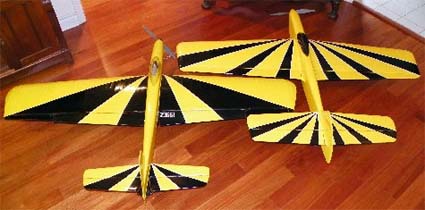
1964 trike version on the left, new one on the right
Some specifications on the plane:
Wingspan: 60 inches
Area: 690 sq.in.
Finished weight ready for battery: 48 oz.
Flying weight: 60-62 oz area.
The plane is covered in Ultracote.
Power: AXI 2826/12 with a Castle Creations Phoenix 45 and Rhino 4S1P 3700mAh battery
Prop: APC 12x6E pusher.
Timer: The new Will Hubin FM-9.
The first flights went very well.
The photo shows my new Legacy along side my "1964" Trike version. My goodness, there is quite a difference in the stabs although the wing area is about the same.
Rick
Return to "What's In This Issue"
Another Comment on Bob Kopski's BDM
From Jim Halbert
Hi Ken,
I read the article by Bob Kopski on a BDM i.e. Coulomb Counter. (August 2010 issue of the Ampeer KM) The only way to fly! Can you give me his email address? I would like to build one.
Bob's email address is: kopskib@gmail.com KM
To bad they are not available. Castle would be the guy to do it, but I think they have lost their way. I spent a huge amount for the ICE ESC. What for?
In big planes I simply use two of the small A123 batteries in series. 900mAh @6.6V. Works well. KISS. As a side benefit, the main battery pack is disconnected from the motor making set up and tweaking a little less of a worry. Ever bump the throttle by accident? I hate that.
Thanks,
Jim
And a follow-up email from Bob Kopski
I'll do my best to help anyone who inquires.
Now that I have several more planes outfitted with BDMs, I'm logging more battery data.
Here are two recent examples:
AMPEATER (a small sport bipe)
1.742, 1.717, 1.721, 1.752, 1.744 recharge AH
FROLIC (a sorta 3-D configuration)
1.585, 1.585, 1.593, 1.576, 1.571, 1.574, 1.555, 1.568, 1.539, 1.572, 1.571, 1.564, 1.584 recharge AH
These values are using the same assortment of batteries - all 3 cell, 2.1 or 2.2 label AH, randomly installed - TP, Hyperion, Zippy, or Turnigy brands. The BDMs are "calling the shots" no matter the pack. As you can see, the two BDMs are set slightly differently but that within the data there is very little spread in the recharge values - especially when one considers the variables associated with go-round, approach, landing, taxi back following the in-air "alert". The highest-to-lowest value ratio for FROLIC is only a 3 1/2% spread. I have no easy way to check if there is any contribution to the data spread from the 3 randomly deployed FMA 4S chargers I'm using - but it's hard to imagine all 3 reading exactly the same recharge value - hey - everything in electronic life has "tolerance"!!
BTW - these data are from flights spread over about one month - I've not had any sessions as the one you describe! Actually, I've only been out 3 times in July - it's been too damn HOT. My typical time-on-field is <2 hours.
Bob
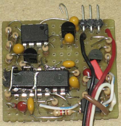
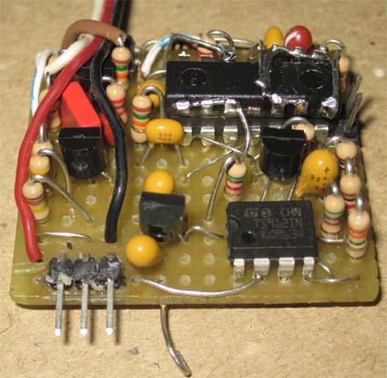
Bob sent along the schematic and pc hole board layout. I have posted them to the EFO site at:
BDM_9_Sch1.pdf
BDM_9_Brd1.pdf
He also noted that he still does not have any "how to" writing in place.
Here are the photos that Bob sent along as well. KM
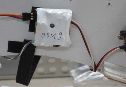
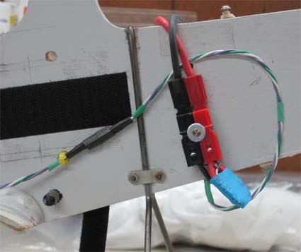
He did add, "A few early notes: The layout shown is for hole board that has a strip pattern in place. The small black rectangles show cuts in these lands. The large patterns are shown 2X and the small patterns are 1X - although I don't know if the .pdf conversion / email process could alter the actual dimensions. (The originals are in TurboCad TCF files.) The hole grid is 0.1". Note that there are both top and bottom views shown in the 1X patterns."
The installation photos are of a profile Bipe ("Ampeater") that's about 23 years old, retrofitted with brushless power - and now with a BDM.
Return to "What's In This Issue"
A Couple of New Models from Bob Aberle
Ken,
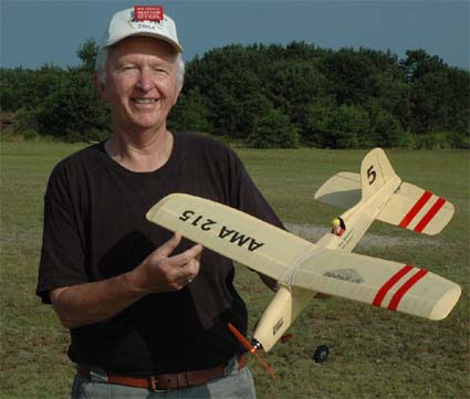
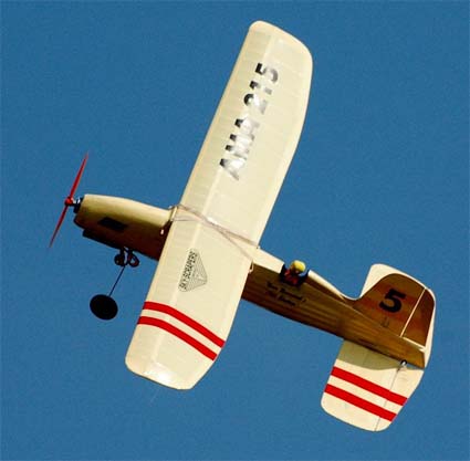
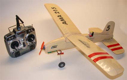
Thought you might be interested in my latest vintage RC model that will be in the August RC MICRO WORLD. www.cloud9rc.com
It is a reduced size version of Norm Rosenstock's 1950 "ELECTRON" which was the first RC design to be published in FLYING MODELS (December 1950).
As a 12 year old in 1950 I held the original for Norm at the old Curtiss Airport in Valley Stream, Long Island.
This little 125 square inch, 7 ounce, 33-watt replica, flies just great! Keep in mind that 1950 was two years BEFORE the advent of 27.255 MHz RC and kits like the LIVE WIRE TRAINER and the Guillows TRIXTER BEAM.
The design itself looks partly like a Walt Good RUDDERBUG and part Henry Struck, NEW RULER.
My reduced size version is only 125 square inches and weighs just 7 ounces. It flew like a dream last Saturday. I've attached several photos. Motor is an E-Flite Prk-250 on a GWS 6x3 prop and a 2-cell 800mAh pack. Power is 33 watts (4.6 amps) for a 76 watts/lbs power loading. Radio is a DX-7 and AR 6110 receiver.
Norm, of course, is thrilled out of his mind. I think it is certainly a fitting tribute to his 70 or more years in our hobby.
Also of interest is my 16 ounce, 200 square inch "PARK PATTERN" design that just appeared in FLY-RC. This plane runs about 100 watts input power and has flaperons (separate aileron servos). Interestingly, I first used my Aurora system and no one could get the flaperons to work. Not even when Hitec folks tried at our NEAT Fair. So I swapped in my Airtronics RDS8000 system, which is difficult just to set a new memory position, yet the aileron function was easy -- you figure?
All around, the friendliest Spread Spectrum system I have right now is the Spektrum DX7! What can I say!
Bob A.
Return to "What's In This Issue"
Hantelmann's Fokker DVII
From Juan Vidal Miguel anajuanharo1@telefonica.net
Hello Ken:
I am embarrassed because my English is very bad. Sorry, I will try to write this letter in the best way I can.
Juan, thank you so much for sharing this great looking plane with us! Your English is far better than my Spanish. That is for sure. KM
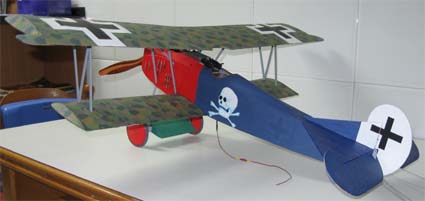
I decided to present to you my latest project: the Fokker DVII that was flown by Lt. George Hantelmann in summer of 1918 at 1/12 scale. All was made in balsa and ply.
I found dwg plans on the Internet. I modified almost 95 % to reproduce the proportions and structure, of this Fokker in detail. I spent a lot of hours studying the documentation about the Fokker DVII (Osprey; Windsock...), authorities in German WWI aviation (Dan San Abbot, Miller...) and several projects of D VII restorations.
I am very proud of the final result because all it was made by my hands in one year from the drawings to the final decoration.
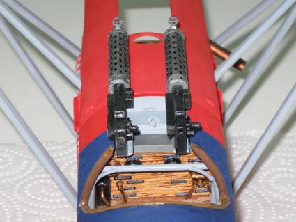
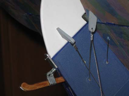
I tried to copy all of the details that the scale and my hands would allow me to do including the dummy six cylinders BMW DIII au engine, two Spandau machine guns, the motor cowling, the clocks, the seat, the landing gear with up/down dampening, the scale wheels and the laminated wooden prop.
The serial number was 382/18 and it was built in Fokker Factory. It was painted in red (nose) and deep blue the rest of the fuselage as well as the rest of Hantelmann�s unit, Jasta 15. The wings and stab were covered white lozenge camouflage.
In my model, it was first covered whit so-lite (Solarfilm) cream colored and to reproduce the lozenge with a second covering with printed tissue (home printer and white Japanese tissue). I think that the colours and polygon schemes are very accurate and the imperfect tissue looks more realistic than the smooth airbrush finish.
If you want you could visit my project at this forum thread: www.miliamperios.com/foro/aeromodelos-escala-f4/fokker-vii-pequena-escala-t135117.html. It is in
Spanish, I am sorry.
Specifications of my model:
Scale: 1/12
Span: 800 mm 31.5"
Wing Area: 17.3 dm2 = 268 sq.in.
Ready to Fly Weight: 600g = 21.18 oz.
Wing Loading: 34.7g/dm2 = 11.38 oz./sq.ft.
Wing Cube Loading: 8.3
Channels: 3
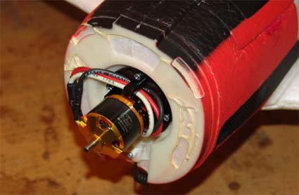
Motor: Great Planes Rimfire 400 950Kv;
Prop: MasterAirscrew 10x5 beach wood prop;
Battery: LiPo Thunder Power Prolite 11.1v 1350 mAh
ESC: Electrifly 25A
Servos: two Jamara Atom MiniBlue of 4.4 gr
Transmissions: pull-pull 0.5 mm wire
I sent you this information when it was almost finished. I had only have to trim the rudder and elevator and set the CG. It is very difficult with two babies to find the time to fly it. I think it is a little heavier and it is probably that take offs and landing will be complicated. I was worried that perhaps its first flight would be the last, but it will go to the end wearing the best cloths like a dandy.
Fortunately the first flight was a success. I am so proud and very happy and I can say that it flew and after landing could fly again.
On the first flight we realised that it was a bit tail heavy. After moving the CG a bit forward (additional 10g of weight in the nose) it flew very nice and gently at half throttle (motor trust at 100% is 630g. Yes, it is too much motor, but I think that it is better to have a big motor and less nose weight.
In a lot of WWI models the CG is a critical point because, for example this Fokker, one gram in the tail is equal to five in the nose. To move the CG forward one or two millimeters is equal to adding a lot of weight. The final weight is 610g, but I sacrificed the 1350 mAh battery for a lighter 1000 mAh because it have almost 40g of weight in the nose.
Regards from Spain: Juan Vidal Miguel
Return to "What's In This Issue"
parkzone T-28 Trojan Article Updated
By Ken Myers
On September 1, 2010 I posted a complete update to my review of this plane. The entire article/review on this plane can be found at: www.theampeer.org/t28/parkzonet28.htm
The plane has worked out extremely well as an aileron trainer for my flight students and as my windy day flier. I cannot recommend it highly enough! Parts of the update follow.
Forward: Sept. 2010
The parkzone T-28 Trojan RTF (ready to fly) that is reviewed here is no longer available. The original parkzone T-28 Trojan is now only available as a PNP (Plug-N-Play) version. The PNP version requires the modeler to supply the transmitter, flight power battery, charger, and receiver. The newer version known as the T-28D Trojan is available as a PNP or BNF (Bind-N-Fly). The BNF version comes with everything to fly the plane except a Spektrum brand DSM2 full range transmitter like the DX5e, DX6i, DX7 or DX8.
Later in the article I note that parkzone came out with a Corsair that uses the same power system. The Corsair is available as a RTF version with everything needed, including a Spektrum DX5e transmitter. It is also available as a PNP.
parkzone has also released a Stinson Reliant in BNF and PNP versions that uses the same power system. While parkzone also has a F4F Wildcat with the same motor, it is a lighter, smaller plane and has a smaller ESC rated at only 18 amps. It is really not suitable for use with "A123" 2300mAh packs.
Since all of these planes use the same power system, my notes on converting the original T-28 for use with "A123" 2300mAh cells also applies to them.
Horizon Hobby has "fixed" the radio problems noted in the original article by deleting the radio from the T-28s and T-28Ds and including a better radio system in the parkzone Corsair, a Spektrum DX5e with an AR500 2.4GHz receiver.
It also appears that they have fixed the main gear coming unglued from the wing problem, as I've not seen or heard any references to that problem showing up in current production T-28s or T-28Ds.
New Updates Regarding Using the "A123" Cells
Back in August of 2008, I originally chose to use the supplied motor and ESC so that I could switch back and forth between the Li-Poly pack and the "A123" 2300mAh pack for in-flight comparisons and to be able to evaluate the plane as "most people" fly it. This is not the "best" way to switch to using an "A123" 2300mAh pack as the prop clearance, with an 11-inch diameter prop, requires either closely cropped grass or pavement.
For a trainer, I find the 84.5 watts in per pound using a 3S "A123" 2300mAh pack more than adequate. Others may want to use the plane with at least the same power loading as the stock plane, which is about 105 watts in per pound.
After about two years of using the plane as a trainer and my windy day flier, I decided that it was time to decrease the prop diameter so that my students would stand a better chance of getting a clean takeoff without 'stubbing' the prop. The 11-inch diameter prop just didn't give them enough ground clearance for consistently good takeoffs.
Solution 1: Increase the cells to four
Drive Calculator (http://www.drivecalc.de) predicts that with a 4S "A123" 2300mAh pack (listed in the program as "M1 (A123 Systems)/(DeWalt 36V)"), the stock motor and ESC, and an APC 10x7E prop the amp draw should be about 21 amps with about 12.3v being supplied to the ESC for a bit less than 260 watts in at an elevation of 287m with an air temperature of 15-deg C.
A 4S1P "A123" 2300mAh pack with wire, power connectors and balance leads weighs 10.9 oz./309.05g (actual wt. of my 4S pack for my Super Stearman). That is a weight increase of 5.89 oz./166.85g over the original 3S 1800mAh Li-Poly pack (142.2g). The stock plane using a 4S "A123": 2300 mAh pack instead of the Li-Poly pack should weigh in at about 36.5 oz./1035g or 2.28 lb. To achieve the same performance level as the stock system requires about 2.28 lb. * 105 watts in = 239.4 watts in for equivalent performance. At 2.28 lb. and with 260 watts in the ratio is about 114 watts in per lb., which is better than the stock system with the 1800mAh 3S Li-Poly pack. At 36.5 oz. the wing loading increases to 16.7 oz./sq.ft. and the wing cube loading to 11.28 oz./sq.ft.
The Problems
Problem 1: The hatch/canopy will have to have an extreme modification to fit the 4S pack and will most likely have to have a new 'floor' added for the pilot figure. (I know this because I tried fitting my 4S pack in my T-28.) This is not a very difficult modification, but will require the ability and tools to do it.
Problem 2: With the expected amp draw of 21 to 22 amps predicted by Drive Calculator, a 25-amp ESC is not adequate, in my opinion. This is only a problem with the early T-28s that were shipped with a 25-amp ESC. It should not be a problem with the new versions that come with the 30-Amp Pro Switch-Mode BEC Brushless ESC. If yours has the 25-amp ESC, I recommend that you get at least an ESC that is rated at 30-amps continuous.
Problem 3: One of the HUGE benefits of the "A123" 2300mAh cells is that they can be charged very quickly at 10 amps or more. A 4S pack of these cells requires a relatively expensive charger to put this advantage to work. One of the least expensive I found is the iCharger 106B+ for $99 plus shipping and appropriate adapter for the balance lead.
While requiring some 'extreme' modification to the hatch/canopy, this is the easiest and cheapest modification for using the "A123" 2300mAh cells if you already own a charger capable of charging these cells at at least 10 amps. Also, the stock wheels can be used, if desired.
Next I discussed in depth the other alternative when using a 3S "A123" pack - "Solution 2: Change the Motor and ESC to get more power from the 3S pack". The discussion leads to my choosing the following items to update my T-28. There is also a comprehensive guide to updating using other motors and ESCs.
Cost of my upgrade
Scorpion SII-3014-1220 from gobrushless.com $61.41 + ship $6.32 = $67.73
Castle Creations Thunderbird 54 from Todd's Models $40.99 + ship $5.66 = S46.65
HobbyZone* T-28 Trojan & Corsair Motor Mount for the Stock 480/Universal - Item #A100018 from Custom RC Parts $19.99 + ship $1.56 = $21.55 (www.customrcparts.com)
Total = $135.93 Way more expensive than using a 4S "A123" pack with the stock equipment!
Why Did I Choose the More Expensive Option?
New Motor installed
With over two years of using this plane as a trainer with my students, why did I change the power system? The power itself was way more than adequate for training purposes, as the plane requires very, very little power to fly around sedately training students. It had sufficient power for all typical aerobatics including extended knife-edge flight.
The 11x8 prop gave my students real problems with takeoffs on anything but the ideally mowed grass. I wanted to reduce the prop diameter to give them a better success rate on takeoffs. Since the ESC that came in my version was the 25-amp ESC, adding a cell meant, at least a new 30-amp ESC. That would have been a cheaper alternative for me, as I also have a FMAdirect CellPro 10S charger that can charge a 4S pack of "A123" 2300mAh cells at 10 amps. But the stock motor in my plane had an 'odd' problem after the last time my student took it up. After we landed and I had recharged the battery in 8 minutes using a Zip Charge, the motor would not start again. I'm not sure why, as when I checked everything out at home after the session, everything was working fine. I'd never had that happen before.
I did find that the original motor mount was cracked from years of not so perfect landings by my students and myself, so I decided to purchase the aluminum one from Custom RC Parts and that would also allow me to fit the new motor as well.
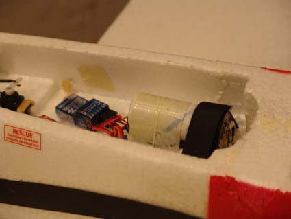
The battery had to be moved rearward to compensate for the added nose weight of the new motor and motor mount. The battery was originally positioned in the cutout to the right of it in the photo.
The complete article has a lot more information and makes suggestions for using specific power systems with a 3S "A123" 2300mAh pack.
(A Full Flight Report and More at
http://www.theampeer.org/t28/parkzonet28.htm)
Return to "What's In This Issue"
Some Excellent How to Videos Posted to YouTube
Lucien Miller of Innov8tive Designs has posted some excellent How to videos. Check them out soon.
How to Change a Shaft in a Scorpion Motor
How to Change the Bearings in a Scorpion Motor
How to Solder Bullet Connectors onto your Speed Controller
How to Solder a Deans Connector onto your Speed Controller
How to Program a Scorpion V2 Speed Controller
How to Oil the Bearings in a Scorpion Motor
How to Download and Use the Scorpion-Calc Software, Part 1 of 2
How to Download and Use the Scorpion-Calc Software, Part 2 of 2
Return to "What's In This Issue"
| 
