 |
Flying High With Electric Power!
The Ampeer ON-LINE!
Fly the Future - Fly Electric! |
|---|
Site Table of Contents
| President: | Vice-President: | Secretary-Treasurer: |
| Ken Myers | Keith Shaw | Rick Sawicki |
| 1911 Bradshaw Ct. | 2756 Elmwood | 5089 Ledgewood Ct. W. |
| Commerce Twp., MI 48390 | Ann Arbor, MI 48104 | Commerce Twp., MI 48382 |
| (248) 669-8124 | (734) 973-6309 | (248) 685-7056 |
 | ||
| Board of Directors: | Board of Directors: | Ampeer Editor |
| David Stacer | Arthur Deane | Ken Myers |
| PO Box 75313 | 21690 Bedford Dr. | 1911 Bradshaw Ct. |
| Salem, MI 48175 | Northville, MI 48167 | Commerce Twp., MI 48390 |
| (313) 318-3288 | (248) 348-2058 | (248) 669-8124 |
| Upcoming EFO Flying Meeting: Saturday, November 5, 2022 Time: 11 a.m.
Place: Midwest RC Society 7 Mile Rd. flying | ||
| EFO Flying Meeting Reminder Remember that the posted dates are tentative for the summer EFO flying meetings. | Looking For FMA Cell Pro Charger Software or Firmware? Where to find firmware and software for FMA chargers. |
| ElectroDynamics' Andy Low Passes A sad note. | Winter Indoor Flying at the Legacy Center Info on Winter indoor flying in Brighton, MI. |
| The Upcoming Midwest RC Society Annual Swap Shop Info on this November Swap Shop in Northville, MI. | Skymasters' Winter Indoor Flying in Pontiac, MI Info on Winter indoor flying in Pontiac, MI. |
| Building My Sig 4-Star Forty for Electric Power Ken Myers discusses the build and electric conversion of a Sig 4 Star 40 kit. | What Size Battery to Get? Ken answers this question and shows how the battery size (mAh) question came up. |
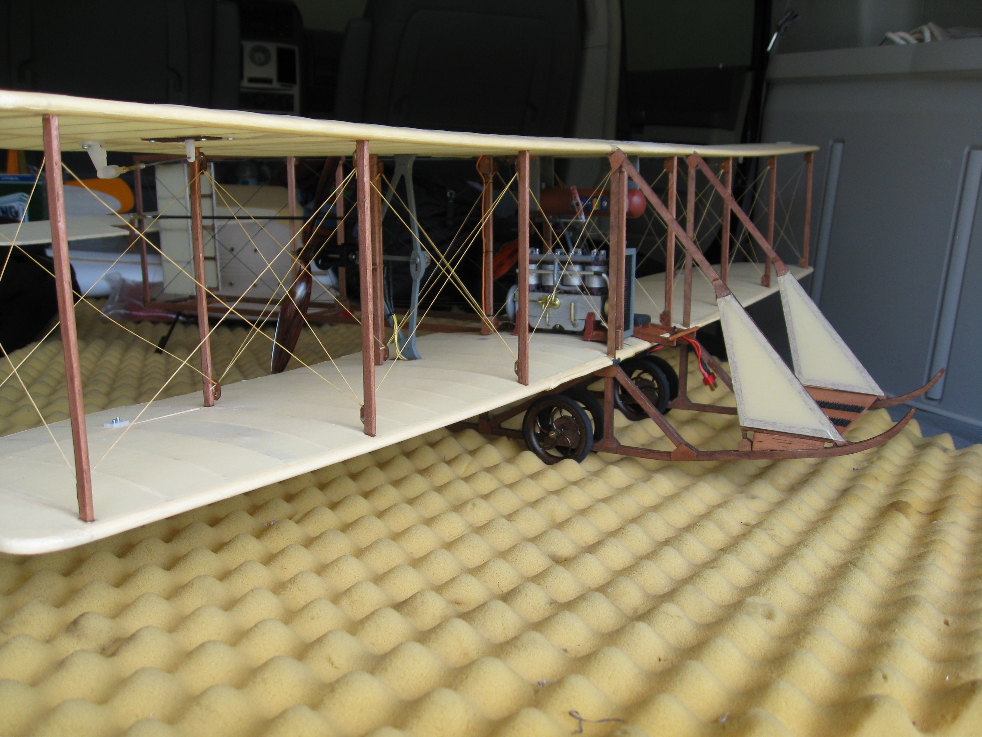
| 1/3-Scale Cub Project A looking back to where we came from article. | Bill Brown, Sr.'s Wright Model B Photos and video links to Mr. Bill Brown, Sr.'s great Wright Model B. |
Please keep in mind that all summer and early fall monthly EFO flying meeting dates are tentative and quite fluid depending on the predicted weather. The meetings are usually on Saturdays, but may change to the following Sunday or even possibly a week or more later. Everyone is welcome and proof of AMA membership is required to fly. The next scheduled EFO monthly meeting is Saturday, Nov. 5 at 11:00 a.m. Looking For FMA Cell Pro Charger Software or Firmware?
It looks like the FMA software site is history. But, Progressive RC has picked up the software for all the FMA chargers, I think. I just downloaded and installed the 10XP app and it worked with no muss no fuss. I did the download and installed the usb driver first, it is there also. Too easy! Lynn ElectroDynamics' Andy Low Passes
I received the following from Chris Tucker to Bill Slabey, president of the Flying Pilgrims, from both Verne and Joe. Long time RC member and owner of Electrodynamics, Andy Low has passed away. Hey Bill, Not sure if you heard yet Andy Low passed away this past Sunday (that would have been Sept. 29 KM) suddenly of a brain aneurysm. He never complained of any pain during the short run issues he was having that day, so from all accounts it appears to have been a peaceful transition. Wanted to let you and the club know ElectroDynamics will continue with business as usual and will remain open. They will be having (was KM) a memorial service for him this Saturday @ 4:00pm (that would have been Oct. 1, 2022 KM) Location: Dunning Park Bible Chapel
Winter Indoor Flying at the Legacy Center in Brighton, MI Indoor flying takes place from November 2rd, 2022 until April 26th, 2023 at the Legacy Center Sports Complex, 9299 Goble Dr., Brighton, MI, 48116 phone: 810-231-9288 Wednesdays from 12:30 PM until 2:30 PM. The cost is $10 per drop-in session. Midwest RC Society Annual Swap Meet Sunday, November 6, 2022
Location
Latitude 42 43 04 North
Admission Charge
Vendor Table Cost
For Information and Table Reservations
Directions
As always, this is the LARGEST and BEST swap meet in SE Michigan! Return to "What's In This Issue" Skymasters' Winter Indoor Flying in Pontiac, MI
Hi All, I'm very happy to announce that we have secured a spot at the UWMSC (UWM Sports Complex), 867 S Blvd E Pontiac, MI 48341, calendar for indoor flying. WE ARE GOING BACK TO TUESDAYS FROM 9AM-12PM! Expected start date is 10/18. More details to follow soon when we open up online sign-in for Gold Cards, etc. Similar to last year we will be offering Gold Card season passes for $150 and single sessions for $10. Thanks,
Building My Sig 4-Star Forty for Electric Power By Ken Myers Several years ago, I built a Sig 4-Star Forty, mostly from the kit but with a hatch added to the front for battery access, a modified firewall for the electric motor and hatch restraint and a bay removed from each wing panel. It has been a great flyer for me over the years. I recently checked the Sig Manufacturing Website for the kit. Sig noted that it is out of stock and NOT discontinued. The following are the unpublished notes from my original build. 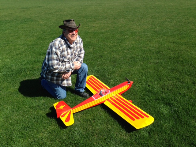 Wing Aileron Conundrum: I tend to 'over-think' what I perceive to be a problem. (AKA, sometimes I'm an idiot!) I spent several days trying to solve a problem that didn't really exist. I thought that the tapered, flat-plate ailerons didn't allow for a good alignment of the aileron to the rest of the wing panel. The only 4-Star 40 completed wing that I had actually looked at did not have the ailerons aligned 'properly' to the wing. That wing had the ailerons in the same plain as the bottom of the wing. That 'raised' the trailing edge of the aileron and gave the wing 'reflex'. I wasted several days trying to overcome this nonexistent 'problem'. I thought of using trailing edge stock and tapering it. I thought of using trailing edge stock with no taper and just having a rectangular wing plan form. I even located some trailing edge stock in my supply and purchased a pair of different widths at a hobby shop. On the third day of wrestling with the "non-problem", I realized that it wasn't a problem at all. The plans clearly DON'T show the ailerons aligned with the bottom plain of the wing! Since there is no reference for the aileron at the root or tip of the wing, the solution was simple, make a jig to set the ailerons as shown on the plans. Then, quite by accident, the solution for aligning the ailerons properly was found in the manual on page 20 - duh! It would have been nice to mention this in the Wing construction section of the manual. "... Use the die-cut Lite-Ply Aileron Positioning Guide to set the ailerons in neutral, as shown on the plans. ..." The Aileron Positioning Guide is noted as APG on the laser cut parts and found on the sheet with the fuselage formers. The guide aligns with the bottom of the wing. There is no note as to how to use the APG in the manual. It looks awkward, since it is aligned with the bottom of the wing, but should work. Lesson learned, RTFM. To Bob or Not To Bob The wing area is listed by SIG as 604 sq.in. From the plans I have in hand, and using the formula for tapered wing area, the stock wing worked out to 610.16 sq.in. and the clipped wing, by the reduction of one bay on each tip side, to 550.62 sq.in. The measured wing span is 59-7/16", NOT the 59-3/4" noted by SIG. With a target weight of 80 oz. (5 lb.);
Sport, sport-scale and trainers have a WCL factor between 7 and 9.99. Advanced sport and advanced sport-scale aircraft have a WCL factor between 9 and 13.99. Should I Tip or Not? Rounded wing tips were added, since aesthetic changes were also made to the empennage and canopy. Balsa wing tip gussets were added to the rounded tips. Wing Construction Notes: CAUTION! The kit that I used was purchased through a local shop near the end of October 2014. They had to order it from SIG, so it was 'fresh' stock. The wing panel plans are correct for the center section but the rib spacings are incorrect from the third center section rib out to the tip rib on both panels. Install the precut shear webs to space the ribs from the center section out to the tips. Keep the ribs parallel to the nearest rib line drawn on the plans. Do NOT install the ribs over the plan and then the shear webs. The Instruction Manual notes that there are Construction started on Tuesday, October 21, 2014. The right wing panel was completed first with no real problem. Unfortunately, the left panel was different from right. I had to redraw the panel extension shown on the plans to use it. Once the left wing panel was mostly completed, the bottom front spar and sheeting were added to right panel. Observation: The left and right wing panels are identical length on the plans, both with the stock span and cropped span. The difference in the left wing panel is where the rest of the left wing plan needs to be cut out and added to the plan. That bay is over 3". The precut shear webs are 3". It can be built that way, but with some material added to that bay's shear web. The added shear web balsa length can come from the excess shear web from the center section. As noted. I redrew the tip part of the left panel correctly and built it correctly. The bottom spar and center sheeting on the left wing panel was completed. Everything was rough sanded and the trailing edge tapered. After more sanding on the wing, I started and drew the top view of the fuselage in CAD to use for the Hitec HS-225MG servo change to behind F3 and to use straight pushrods not the provided flex rods. I also drew the fuselage side in CAD to make the servo changes and firewall change. I also thought about lowering the horizontal stabilizer but I was unable to get a good pushrod run doing it, so I gave up on that idea. Changes were made to reposition the firewall and add the battery. 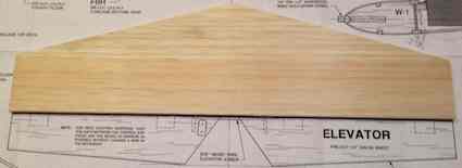 I discovered that the precut horizontal stab was larger than the one shown on the plans and was pointed instead of being straight across at the fuselage, as shown on the plans. The plans did not match most parts. There were slight differences, which made calculating the elevator and rudder servo placement difficult. Unfortunately, about every thing in this kit was a bit frustrating, but the majority of the 'problems' I had to overcome were caused by my changes to electric power. The top was cut off the original plywood firewall. The servo openings in the wing panels were cut. The servo rails for the wing servo and rudder/elevator servos were cut and glue to fuselage sides. I made a template for, and cut, the rear pushrod exits. Finally the wing panels were epoxied together and the aileron torque rods were added. A slot had to cut for the new firewall position in the fuselage doubler as well as a bit more room for the battery tray floor. The front of the firewall was covered with Econokote and the motor trial fitted to the firewall. The 1/4" elevator joiner was epoxied to the elevator halves. Note that the instruction manual states the elevator halves are 3/16". They aren't. After wetting, the 3/32" sheeting was on top of the fuselage and taped in place over night. The torque rod blocks were sanded the torque rod blocks and the 1/4" aileron stock was shortened for the "bobbed" wing length. It was then that I found the ailerons stock to not be identical.  Once the main construction was finshed there was a lots of this and that and finish work and finish work to be completed. I located a pilot in my parts bin and then cut out the canopy and fitted it to the fuselage. The wing center section was fiberglassed. The ailerons were "Monokote hinged" to the wing and the horizontal stabilizer tips were glued on. That finally finished up the assembly. A tail wheel assembly was located in the parts bin and attached. 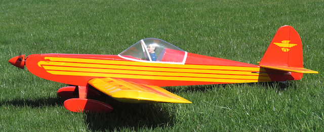 The first test flight felt like flying an old friend, and it has been a great flying plane since then. The Specifications
What Size Battery to Get?
Jim has been working on this plane for awhile now and it is just about ready to go. KM I'm planning to buy the motor etc. for the Fledgling and the Power System Calculation indicates a 2300mah 4s battery. Will a 2200mAh battery be OK or should I go to a higher mAh? Jim Hi Jim, A 2200mAh would be fine, and it is a more common size than a 2400mAh, and I've never seen a 2300mAh. Later,
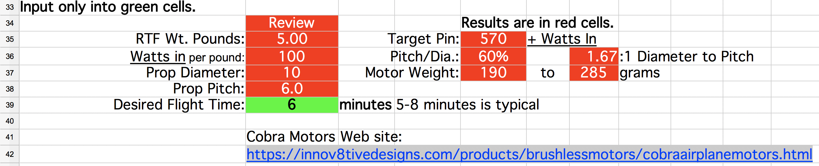
This is the spreadsheet Jim was working from. 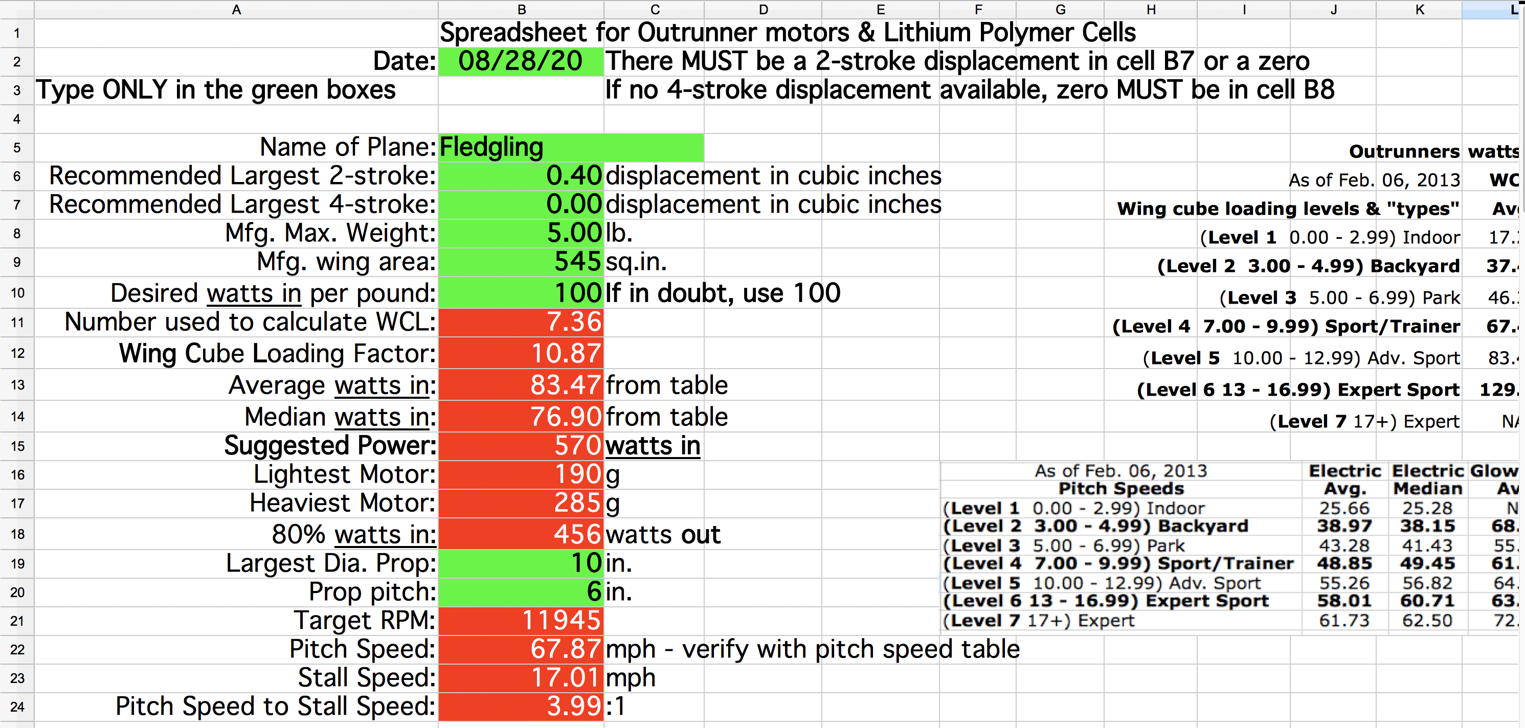
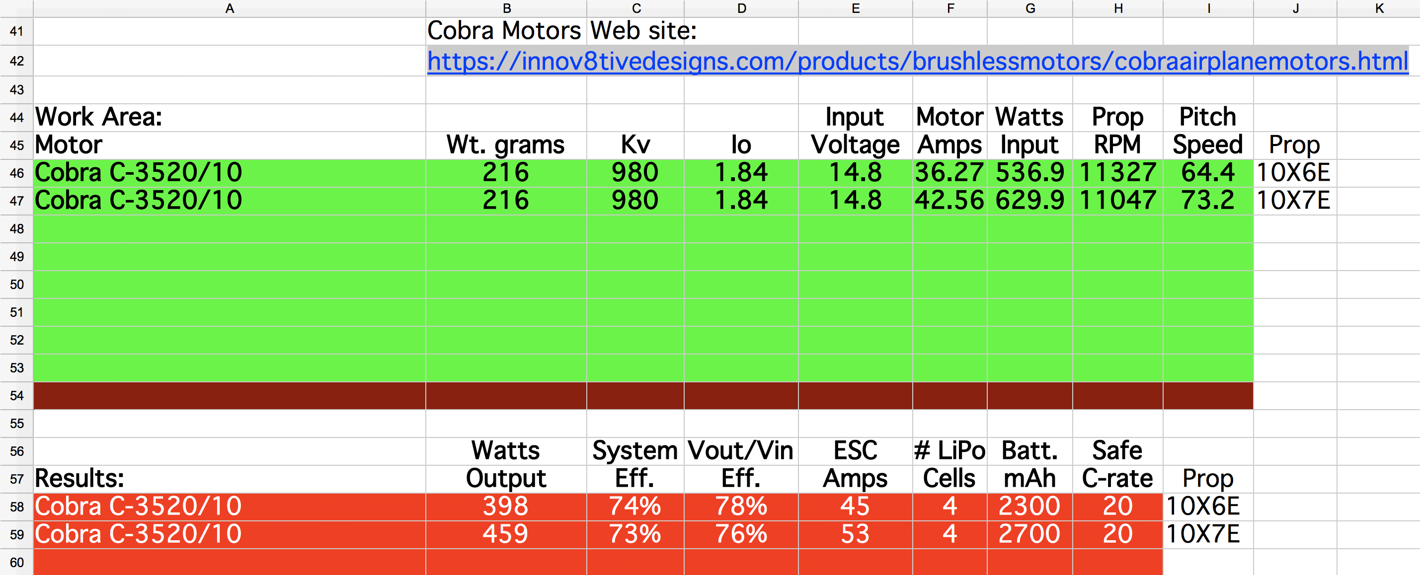
The Cobra C-3520/10 is the recommended motor with a 50ish amp ESC. If a 10x6E is used, the recommended pack size is a 4S 2300mAh. That's were Jim's question arose. To get about the same flying time using a 10x7E, the pack should go up to a 4S 2700mAh, but a 3000mAh pack should be fine as well. To get the spreadsheet that was used here, see the article, "Selecting an Electric Outrunner Motor Power System for an ARF, Kit or Plans Built Electrically Powered or Glow Conversion Prop Plane", By Ken Myers, The date of publication was March 2017, Article and Spreadsheet Workbook updated April 2021". 1/3-Scale Cub Project
I have a thread on the RCG Scale Electric Forum on finishing my Sig J-3 Cub, started over 30 years ago, for electric power. I am using an AF 25 geared, brushed cobalt motor and AF 211 speed control, a Kool Flight UBEC to power the servos and the SPC port of the Optima 6 receiver to power the receiver only. I have the system up and running after nearly cremating the UBEC as a result of plugging in the power from the motor battery into the SPC port with reversed polarity. The old AF 25 can handle 25 volts nominal coming out of two 2200 3S Lipos in series. The AF211 ESC and Kool Flight UBEC can handle up to 35 volts. The Hitec Optima receiver itself can handle up to 35 volts through the SPC port but the receiver bus can only handle normal 5-6 volts. 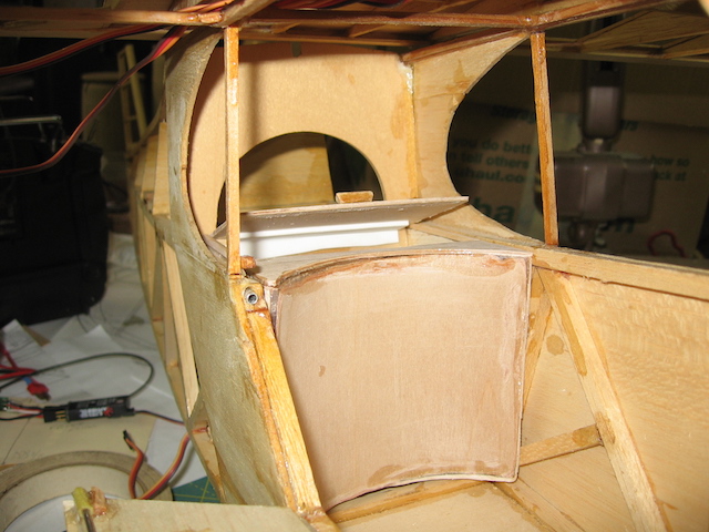 I am detailing the Cub's cabin including concealing wiring and RC gear. Two lipos will lay on bottom of cabin with Velcro and Velcro straps. False cabin bottom will velcro to top of lipos and will have seats and sticks, etc. Access to batteries will be through functional side door/window. 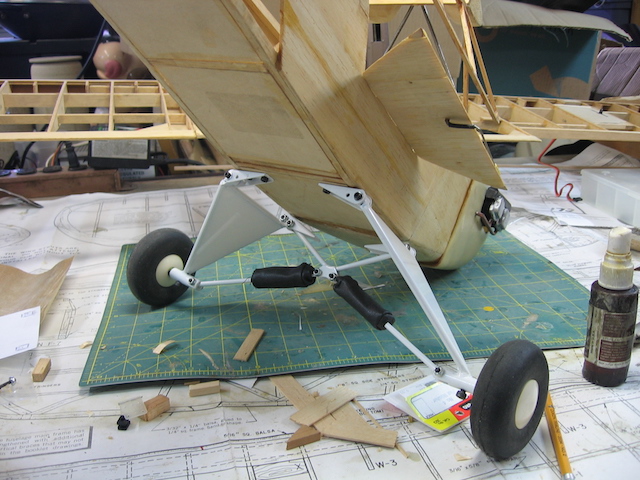 The photo shows the E-Flite Super Cub 25 bungee landing gear with Banner Streamlite wheels and rear baggage tub that conceals receiver, UBEC and Lipo Saver. Model will have single piece wing and Solartex cub yellow covering from Balsa USA. I'm thinking of upgrading to the Aurora 9 transmitter as a more scale model friendly transmitter than my old Eclipse 7 with 2.4GHZ module Keep up the good work on the Ampeer and Merry Christmas and Happy New Year 2013. Gary Gullikson, Garden Grove, CA Printed now to remind us where we came from and I just found the file - dang! Thanks Gary. Bill Brown, Sr.'s Wright Model B
And There is Video A few years ago, Mr. Bill Brown, Sr., long time Midwest RC Society member and EFO member, built a beautiful scale model of the Wright Model B. Here are a few photos and links to a couple of short video clips on the day of the maiden. .JPG)
Test Pilot Keith Shaw on the left and Mr. Bill Brown, Sr. on the right
This clip shows Keith Shaw, the test pilot, doing the successful maiden takeoff. Keith Shaw continues the maiden and then lands. To Reach Ken Myers, you can land mail to the address at the top of the page. My E-mail address is: KMyersEFO@theampeer.org |
.JPG)
.JPG)
.JPG)