 |
Flying High With Electric Power!
The Ampeer ON-LINE!
November 1997
The Club Newsletter of the Electric Flyers Only, Inc
AMA Charter 2354
Walled Lake, MI, USA
Editor: Ken Myers
Fly the Future - Fly Electric!
|
| President: | Vice-President: | Secretary/Treasurer: | Board of Directors: | Board of Directors: |
| Ken Myers | Richard Utkan | Debbie McNeely | Jim McNeely | Jeff Hauser |
| 1911 Bradshaw Ct. | 240 Cabinet | 4733 Crows Nest Ct. | 4733 Crows Nest Ct. | 18200 Rosetta |
| Walled Lake, MI 48390 | Milford, MI 48381 | Brighton, MI 48116 | Brighton, MI 48116 | Eastpointe, MI 48021 |
| (248) 669-8124 | (248) 685-1705 | (810) 220-2297 | (810) 220-2297 | (810) 772-2499 |
| Mailed Ampeer subscriptions are $10 a year U.S. & Canada and $17 a year world wide. FREE on-line! | The Next Meeting:
Date: Thursday, November 6 Time: 7:30 Dublin Community Center, on Union Lake Rd. north of
the village of Union Lake on Union Lake Rd.
|
Couldn't Make It to KRC? - Check It Out on Video! from David Segal
76641.2074@compuserve.com
 Despite threatening weather forecasts and two days of high winds, the Keystone
RC Club Electric-Fly was great fun. A video will be available from the following outfit.
Despite threatening weather forecasts and two days of high winds, the Keystone
RC Club Electric-Fly was great fun. A video will be available from the following outfit.
Contact:Reel-Tour Productions, P.O.Box 466, Perkasie, PA 18944 --- Phone: 1-800-95-VIDEO ---
Price is $23.00
Regards, Dave
Tach It! from: Tony N. Criscimagna tnc@ulster.net
TNC ELECTRONICS, 2 White's Lane, Woodstock, NY 12498 --- Tel: (914) 679-8549 - Fax:
(914) 679-5542
Sept. 15, 1997
Dear Ken:
We have mutual friends, I believe....Bob Kress and Bob Aberle. In fact Bob
Aberle sent a fax of the September newsletter to Bob Kress who in turn faxed it to me.
Since the "$130" tach alluded to by Mr. Davis in the referenced
news letter is a TNC Electronics tach I felt it necessary to try to shed some light on this technology.
This attachment memo, therefore, is a commentary on the September issue of
your fine newsletter. I checked out your home-page and it is really a very well structured and written homepage. I hope my
homepage, that is being written now, will be only a fraction as good.
Why Is It Difficult To Optically Measure RPM from a Prop
Have you ever looked, up close, at a slow turning fan? What you see is the
background light interrupted by the blades passing in front of that background. If the background is bright, then you see moments
of darkness as each blade momentarily hides the background from your view. However, if the blades are brighter then the
background, you see moments of brightness as the bright blades move into view and passes by. If a light source, like the sun for
example, is reflected brightly from each blade of the fan as it turns, you see a series of bright light flashes.
The above analogy gives us a basis for understanding how the signals, to which a
tachs optical photo transducer must respond, are generated. Its optical system must respond properly on a bright day and on an
overcast day; in the shade and in the sunlight; in front of the prop, behind the prop; with backgrounds of grass, concrete, blacktop,
gravel and just plain dirt; with small, large, fat, slender, black, gray, plastic and wood props; up close and at a distance away
(perhaps 2-3 feet) from the prop; and at prop speeds of 1000 to 150,000 rpm (turbines).
The signal that is generated by a rotating propeller, even under the best of
conditions, is a very poor signal. Imagine someone standing 3 feet away from you, waving his hand from side to side. Just how
much of a change in ambient light does this produce for your eye to see or for an optical sensor to detect. Not much at all. Now if
that person were moving his hands from side to side only an inch or so in front of your eye you would see large changes in
brightness. When the hand is directly in front your eyes, it would effectively shade your eye from most of the ambient light.
When the hand is not in front of the eye it would be able to see the full ambient light.
Depending on these many different conditions the types of signals that must be
properly handled are almost limitless.
Designing a good optical tachometer is therefore not a simple task. A tach's light
sensor and amplifying circuitry must be able to handle signals that have widely varying shapes, amplitudes and frequencies. For
example the photo transistor signal from a 12" prop at a distance of 3 feet cannot even be seen on an oscilloscope operating
with a sensitivity of 5 mv per centimeter. This same prop at a distance of 0.5" will produce many hundreds of millivolts of
signal. to design a tach to operate properly in the field it should have the following:
First a tach needs an optical light transducer that must:
- sense weak signals generated by small props on dark day at 2-3 feet or more.
- keep up with props (turbine rotors) rotating to 150,000 rpm
- be correctly priced for a reasonably priced tach
Second a tach needs circuitry to:
- greatly amplify the weak signals from the photo transducer
- reduce, when necessary, saturation of the optical transducer due to high ambient light
- clip very strong signals
- shape pulses to make them square in shape
- narrow all pulses of varying widths to one very narrow width to prevent spurious counter stepping
Third a digital tach needs circuitry:
- to accurately measure the pulse counting periods for either 1, 2, or 3 blade props
- to count for that time selected period
- to display that count so it can be seen even on bright days
Various Ways To Optically Measure RPM from a Prop
There are four basic ways of electronically measuring the speed of a motor using
an optical tach. First a strobe light can be used. The second approach is to measure time interval for one rpm. The third is to
count for a prescribed period of time.
The second approach measures the time between prop impulses or of multiple
prop impulses, to compute the period (T) for one revolution. The reciprocal of period, frequency, is then computed (1/T) and
multiplied by a constant that results in rpm. This constant can be changed for 1, 2, 3, or 4 blade props.
This approach obviously requires a micro-computer. The software for this
approach sounds simple but is full of pitfalls.
Depending on the quality (stability) of the micro computer's crystal oscillator, that
controls the accuracy of measuring the time interval, the results can be quite good.
The third approach, is to count the number of prop impulses for a fixed time
period. This is essentially frequency (impulses per second). If the counting time period is selected to be exactly 0.3 seconds then
the count will be the engine's rpm in 100's of rpm. For example if an engine is running at 10,000 rpm the count in 0.3
seconds will be exactly 100. Mentally adding two zeros results in 10000 rpm. With a counting time base of 0.3 seconds for two
blade props and 0.2 seconds for three blade props, etc., no mathematical processing is necessary.
Using A Frequency Measuring Multimeter As A Tach
The idea of using a multimeter's frequency measurement capability is not new,
nor has anyone claimed it was. It is a simple way to measure RPM, which after all is frequency. However depending on the unit
selected there may be a few minor concerns with this approach.
Cost Savings ???
Money is not saved by using a multimeter unless a modeler already has one.
One of the least expensive multimeter suggested (by Mr. Davis km), the DM16XL from Wavetek costs about $100.00 as
specified in the newsletter. TNC's new PT10S tach also costs about $100.00. The more expensive candidate DMM870 has
been discontinued and is replaced by the Tektronix DMM916, DMM914, DMM912 cost $289, $249 and $199 respectively.
The DMM912 is the least expensive and therefore most suitable. There is no
argument here...if you already have a multimeter you can use it for a tach. Who can argue against that??....assuming, of course
that it works well as a tach...
Accuracy
Second, the accuracy of some of the multimeters is not quite as good as the
PT10S although I'm sure they are good enough. The accuracy of the 3 Tektronix multimeters is 0.01% of full scale plus 10 low
digit counts. The accuracy of the DM16XL is 0.1% of reading + 2 counts.
| Model | Scale (Hz) | RPM | Calculated |
| DMM912 | 0-400 Hz | 0-12000 rpm | +-4.2 rpm |
| DM16XL | na | 12000 rpm | +-18 rpm |
| PT10S | na | 100,000 rpm | +-0.5 rpm |
| PT10s | na | 10,000 rpm | +-0.05 rpm |
The DMM912 at $199 with a +-4.2 rpm accuracy figure is barely accurate
enough for 10 rpm resolution, but I don't believe that the DM16XL with +-18 rpm is good enough for 10 rpm resolution.
Sensitivity and Stability
The newsletter describes the optical/electronic front end of this unit as an NPN
photo transistor, a resistor and a battery. The sensitivity of such a simple front end would be very poor, and most likely would not
work well if at all under all field and weather conditions. If this front end was held right up to the prop, perhaps no further than
1", it might work if it was a bright day. I have not tried such a simple circuit, and I base this conclusion on frequent reports
from modelers who try to use some of the less expensive digital optical tachs available at almost any wholesale distributor for a
"bargain" price.
When they call to buy a TNC tach, they frequently report that these
"inexpensive" tachs can be very frustrating since they don't always work. Almost all of these tachs use a low
sensitivity photo resistor and a one stage op-amp for gain. I doubt that even with the poor gain of the photo resistor, that
these tachs with the one stage amplifier would not be at least as good as a photo transistor and a resistor - yet even they are not
an adequate design, just an inexpensive one. If the simple photo transistor-resistor design is really adequate then someone should
inform the designers of these cheapy tachs that they could save a lot of money and a lot of circuit board space by just using a
photo transistor and a resistor.
The TNC Design
All models of TNC Sensi-Tach's use the same optics and amplifier circuits. The
photo detector is a high quality photo transistor. The signal it generates is controlled by an anti-saturation circuit that allows full
sensitivity regardless of the ambient brightness. The photo pickups easily saturate and develop zero signal, especially the sensitive
ones.
The next two stages of the amplifier are hi gain stages that are followed by a
pulse shaper that is also a hi gain stage and a threshold stage. The last stage is still another pulse shaper. About one-fourth of the
circuit board is used up for signal processing. The remainder is used to count and display the readout.
It is these circuits that allow the TNC tachs to function under the very adverse
conditions found in the real world as described above.
The TNC 10 RPM Tach Design
The third design approach (described above) is the one used in all TNC
Electronics' tachs for 100 the rpm resolution. To get 10 rpm resolution the impulses from the prop must either be counted for 10
times the 0.300 seconds, that is, for 3.0 seconds or the number of prop impulses generated by the prop in that 0.300 sec time
period must be multiplied by 10. As awkward as this former technique may seem it is not impractical.
However in order to avoid the 1 update every 3 seconds and retain the 3-5
updates per second and still increase the resolution by a factor of ten, the number of prop impulses is multiplied by 10 and counted
for the correct time period (see above). This same technique can even be extended to provide 1 rpm resolution.
As with the computer approach, the accuracy of the TNC tachs is controlled by a
temperature controlled crystal oscillator, that boasts an accuracy of 5 parts/million or 0.0005% from -10 degreesC to 70 degrees C.
Since the TNC tachs have upper limits of from 60,000-80,000 rpm (for the 10 rpm tach) to 100,000 rpm (for all others) the full
scale (FS) accuracy of the 10 rpm tach is +-0.3 rpm (0.0005% x 60,000 rpm). To support 10 rpm resolution, a tach should have at
least an accuracy of 1 rpm, or a factor of 10 better accuracy than resolution. Resolution without accuracy is totally meaningless.
The TNC Sensi-Tach PT10S model reads out in both 10 and 100 rpm
resolution. When depressed, a small push button on the side of the tach switches it from the default readout resolution of 100 rpm
to the 10 rpm resolution readout. This tach is a new model and ad copy has been sent to most leading magazines. Expect
publication in several months.
The original 10 rpm Sensi-Tach (PT+10) was designed for the Madiera racers at
the request of many of the contestants. It sold for $130. The new PT10S with the extra switching function now sells for $99.95.
The reason the switching function was developed was that there are times when
too much resolution can be a hindrance. Engines that are not running smoothly (souldn't be a problem for us! km) can cause a lot
of bounce in the 10's digit that can be make reading difficult. One case of this is an engine at idle. In the PT10S the 100 rpm
resolution is always available. When peaking engines, it is often more convenient to use the 100 rpm resolution for coarse
adjustment while approaching the peak and the 10 rpm resolution for the final adjustment at peak.
This problem, of course, does not occur to the same degree with electric motors
or helicopters or large engines with massive props where speed is quite uniform.
Conclusion
I conclude therefore that:
- no money is saved...unless you already have a quality multimeter (I believe that to be Tom Davis's original point. km)
- the accuracy of the multimeter approach is adequate
- 3. it is doubtful that such a tach front end would be
satisfactory for modeling use. If a first class front end were designed to go with these multimeters, then the system would work
just fine...
TNC TACHS:
Common characteristics:
- accuracy better than .5 rpm
- operate at distances of at least 2-3 ft from prop
- operate well on cloudy or sunny days
- steady readout
- long battery life - 9V battery supplied
- totally temperature compensated
- never require calibration
Model PT - basic prop tach - 100 rpm res. - max rpm = 99,900 rpm - priced at $79.95
Model PT10S - prop tach - two switchable resolutions - 10/100 rpm with default being 100 rpm. Max rpm in 10 rpm mode is 60-80000 rpm. In 100 rpm mode the max rpm
is over 150,000 rpm. - Priced at $99.95
Model PF - prop/fan tach - designed to operate with plug-able remote optics module cable for use with ducted fan
models. Plug-able optics module also supplied for use as prop tach. - Priced at $104.95
Model JT - jet or turbine tach - designed for use with props, ducted fans and turbines. Max rpm over 150,000 rpm.
Remote cables and plug-able optics module included. Priced at $114.95
SERVO REVERSER:
Designed for use with split elevators, servo operated gear door, etc. where
symmetrical linkages are needed to guarantee synchronized motion of the two surfaces operated fron two separate servos plugged
into one channel. The reverser never requires adjustment of servo neutral, it never drifts, is totally temperature compensated,
pulse output is accurate to within 1-2 usecs.
No servo jitter - totally encapsulated in epoxy for long life - two output cable supplied one with reversed output
and one with no reversal. Size less than 1" x 1" x .3" and weight less than 1/4 ounce. Complete with input and output cables for
only $24.95. This is the least expensive precision mini servo reverser I know of.
I want to thank for Tony and Tom for our education on Tachs! This
is one of our most important items we use, when checking our motor/battery/prop combinations.
I have a challenge for all of you "electronics" experts out there.
Design a light-weight unit to go in a plane to measure RPM, Amps, and motor voltage, and store that data for download
to a computer via a serial or parallel connection. Supply the computer software to display a graph(s) of that data
through the whole flight, and do it for less than $200. Yes, I know it has been done, but the units I've read about are
overly expensive for the "curious", average modeller to afford. How about it? Can it be done, be accurate,
and be relatively inexpensive? km
Return to "What's In This Issue?"
Thoughts on Competition from: Raymond Pike stingray@c031.aone.net.au
http://www.ozemail.com.au/~maaa
Hi Ken,
At 18:57 7/09/97 -0400, you wrote:
>Hi Ray,
>
>Most folks don't want to lay out the bucks for these events (F5B & F5D km). They also require a lot younger
reflexes than most of the folks who can afford to travel to the US e->Nats. F5B has been offered the last 2 years, if 5
entrants >could be found. No one registered.
It's interesting the way particular modelling interest areas develop in different
countries!! Maybe its because most of the e-fliers I know have a glider background, and prefer "glider type" electric
models.
There are more of the traditional "Power type" fliers getting involved
in electric, but I think they are still in the minority here (Australia km).
But, from some of the models I have seen on the WEB pages, they would cost
every bit as much as an F5B model, and much more than a pylon model. Interesting you mention the cost of going to the Nats.
We are still paying off the Master and Visa Cards from our last NATS :-( (Australian km) We travelled about 10,000 km
(6,000 mile) all up. Took us a month, it was a great trip, but I wouldn't want to do it again for a couple of years!!
Hopefully the Sydney based e-modellers will be organizing an &quto;electric fun
fly" before Christmas. It will be interesting to see how well supported this will be. If there are SOME competitions I will try
to go, otherwise I won't bother.
The National Electric Rally that I usually organize, is four days of competitions
over Easter. We try to fit in "free flying time" but no one seems to want to cancel the events we usually run.
This year we ran the following events:
Friday: Scale, Open Glider (as per electric email comp), Sport Cabin and Electric Scramble (max total flight time in
3/4 hour 2 min max per flight)
Saturday and Sunday: F5B (3 rounds) and 7 cell glider (6 rounds ?)
Monday: F5D pylon, 4 minute pylon, sport pylon, and speed 400 pylon.
[Apart from the F5B, F5D and 7 cell events, the rules are made up by the
electric modellers, and sometimes change from year to year.]
I (and I presume a few others) then collapsed in a heap and were little use at
work for the rest of the week!!! I flew in 6 of the events.
> I'm not a competition flier of any type. I just follow the
rule book. At least that's what I did while running the e-Nats two years ago.
I guess you have "lots" of electric events in the USA. We have
about 3-4 main events, and the others are probably less then 15 people, usually from the local region. (Not really a lot, but it is
growing. Most of the regions of our country are now having pretty good sized meets [30 plus folks or more, with several well over
50], and it is growing. km)
>There does seem to be a bit of "lack of direction" as
far a competition goes. I think it mostly comes from the fact that most of the e-fliers I know are more interested in
"perfecting" their planes and flying to what they want to do, and not what some "rules committee&quto;
wants them to do.
I guess "we" ARE the rules committee. If we REALLY wanted to,
we can change our event rules, except F5B & F5D.
Most of the competitors like the 7 cell event - we have had up to 40 entries a
couple of years back, about 20 this year. We have also had up to 20 fliers in F5B, but mainly in the 7 & 10 cell classes. The
maximum entries in open (27 cell) F5B has been about 6. This would have been prior to the 1994 WCs. We had 15 F5B entries
this year.
I like "perfecting" my models too, but I like to be able to measure
how well I am going by seeing how my model performs compared with other fliers. I guess I also like the adrenaline of the
"man on man" competition and the buzz when my F5B model is launched and accelerates away vertically. The
SOUND is also rather nice as it "whistles" through at 100 mph on the end of a lap and then "roars" back
up towards the clouds before starting another set of laps.
I must admit my competition models are no longer competitive by World
standards, but I still enjoy flying them. I am working on a new 7 cell model with the hope that it will be able to consistently
manage the 5 minute flights from less than a 15 sec. motor run (I can only try!)
I guess the best part of this sport is there are endless variations. (within the
electric area as well as the many other modelling types) I cannot ever see myself running out of interests, just time!
thanks for the comments,
best regards, Ray
Return to "What's In This Issue?"
More Thoughts on Where E-Flight is Headed From That Same Side of the World from Lex Davidson
(of New Zealand), ldavidson@xtra.co.nz
Hi Ken,
Good to hear from you. The current address for Drawingboard is
http://www.mcesoft.com/freelt3.htm. Downloaded from that site last night.
Seems to work OK but I still like my Modelcad for Windows.
Not being evangelical, but the conversion process is going quite well here.
Developing into two streams, competition and sport/fun flying. We are having F5B competions about every two months in our
region. Most are flying 10 cell, a few 7 cell. No one has turned up with a 27 cell model yet! Because of price and availablity most
of the serious entrants are using MEGA motors (SP10s). We run the same handicap system as UK (and I think US) but do not
(yet) apply the aera rule to 10 cell models.
Reasons for the progress is (I think)--at the competition end one guy who got
sick of doing it on his own, and started importing MEGA motors and kits and on selling at excellent prices (is also doing Kontronics
now). The comptition glider guys took to these.
At the sport end I think the speed 400 models are a major factor. Some good
models around, low incoming cost and better/different performance to the Electra, Lucifer, Spectra route that a lot of guys have
had a look at and gone away.
We now have two members with Aveox motors. Both very happy. I'm going to
sell the rest of my IC stuff at the next auction and get one. Magnificent motors.
Thanks, Lex D
Return to "What's In This Issue?"
Millenium Falcon Rating from Dennis Weatherly jdwxly@aracnet.com,
Wilsonville, Oregon U.S.A.
Here is another plane to add to your ratings list:
Millenium Falcon from New Creations R/C: rating: ****
An electric sailplane for 035-40 power and 7 to 16 cells. Fiberglass fuselage,
obechi-sheeted foam wing and stab, T-tail. Can be built as a rudder/elevator polyhedral ship or with additional ailerons and/or
flaps. The kit quality was really good. I built the deluxe version, which has the obechi sheeting already applied to the foam
cores. Mine is powered by an Aveox 1412/2Y and 7-16 cell controller, Aeronaut 12x7 carbon folding prop with +5 yoke and
10 - 1700SCRC cells. Current draw is 68 amps static at about 8200 rpm. I removed most of the dihedral (left 5 degrees on each
side) and have ailerons, elevator, rudder and motor on/off. Ready to fly weight is 64 ounces.
The model climbs like a rocket! It can't quite maintain a vertical climb on this
power system, but it only takes 5 seconds or so to exceed a strong winch launch. I can get 5 to 6 climbs like this on one charge.
The handling is quite good, however it needs a lot of aileron differential (I am at 50% and need more). Coupling in the rudder
helps even more. I have dialed in a few percent of down elevator when the power comes on to keep the nose down. The
ailerons are set up as spoilerons for landing, which slows the model down and creates a predictable rate of descent. Deploying
these also required a bit of down elevator mixed in.
All in all, a great ship. It thermals really well, climbs great and even loops and
rolls nicely. I understand that they are getting hard to come by, as Kirk is pretty busy at
New Creations and has little time to produce the kit.
Return to "What's In This Issue?"
The Kopski End of Charge Beeper by Jeff Hauser
7774499@msn.com
It all started when my good friend and flying buddy, Ken Myers, bought an SR
peak charger. It had this neat feature. It buzzes when the battery pack is peaked. This would let him walk around and wait for the
buzzer to go off. All this time I am playing yo-yo with my charger to see if the battery is peaked. I did not want to go buy one of
the SR Chargers because I had just bought a new AF (Astro flight) 112PK. What to do?... Mr. Kopski to the rescue!
In the March issue of MA (Model Aviation) Bob Kopski showed and described
an end-of-charge beeper or EOCB that he had designed and built. He also included a schematic and an assembly drawing that
included a part's list.
First, I scanned the two drawings and enlarged them so that I did not have to use
a magnifying glass to read them. (Having procrastinated until the July issue of MA came out, I would agree with Bob that you
must only read and build off one drawing preferably the assembly drawing.)
Next, I set out to Radio Shack to get the parts that I did not already have in my
workshop. The only thing I had trouble with was the beeper. I stopped at three Radio Shacks and not one of them had the beeper
that was on the part's list (273-065b). So, I settled for the one they all had in stock, (273-065a) which looked to be too tall.
Now having all the parts, I decided to build this while on a trip where I would be
spending a few days in a hotel room. I packed the necessary parts and my Unger UT-300 soldering iron, yes I do keep all my
boxes... all of this fit nicely in a soft sided briefcase. Having a two day layover in a small town in Tennessee, I decided it was time
to build the EOCB. I also found a Radio Shack that had the beeper that Bob had on the part's list. After seeing the two beepers
together... I think the "A" beeper would be too tall for most charger installations.
I got all my parts laid out and my iron setup on the desk in the small room. I
started at the beeper end (but did not put it on until last) and worked to the other end. It all went very fast, too fast, only about one
hour in all.
The pictures of Bob's finished EOCB and his follow up comments in the July
issue helped to speed things up. Having finished the ECOB so quickly I was wishing that I had brought my charger so I could
install it.
Back at home, (four days later) I immediately ran downstairs to my workshop.
The ECOB was finally going into my AF 112PK. I opted to install it inside the charger out of sight instead of using the in-line type
of installation. This is just my personal preference. I like to keep as much out of sight as possible. Having opened the charger I
could see that it was going to be tight. I used the same type of installation as Bob did, cutting off small pieces of a Bic pen housing
to use as spacers. I also had to cut a small section of the board so it would fit around the analog amp meter. I then attached the
whole thing to the heat sink faceplate with cap screws.
Finally, I headed to the garage with a 15 cell 1700 SCRC pack to see if it
worked, it worked great!
In closing, I have a few final comments about the EOCB. First of all, the beeping
sounds only lasts about 3 seconds, but it is loud enough to be heard from some distance. To make the beep last longer, maybe a
larger capacitor could be added or maybe it could be hooked up to beep until you turn it off. These are things that should be asked
of Bob. I have not had the time to do this myself Second, I do think that the EOCB can be made smaller by making your own
board instead of using the one from Radio Shack. But you have to like doing things like that.
Finally, overall this is a very nice add-on for your charger and as Bob has stated
should probably be on all new chargers. Good Job Bob! Also, I would be willing to help anyone in the club build and install the
EOCB into their charger.
You can contact Jeff at 810-772-2499 or via his e-mail address. km
Return to "What's In This Issue?"
MotoCalc Version 3.0 Released
Dear Electric Flyer:
We have just released a new version of MotoCalc, and it is available at our web
page http://www.capable.on.ca/rcstuff.html for a 30 day free evaluation.
MotoCalc 3.00 represents a quantum leap in electric flight motor performance
prediction, offering the following significant improvements over version 2.0:
- Imperial/U.S. or metric input and output
- rate of climb and rate of sink
- motor designer
- multi-bladed propellers
- series, parallel, or any combination mutli-motor wiring
- ganged motors and ganged propellers
- visual lift and drag coefficient estimator
- and more see http://www.capable.on.ca/whatsnew.htm
This upgrade is free to all registered users.
Stefan Vorkoetter, Capable Computing, Inc.
Return to "What's In This Issue?"
San Diego Meet in February 1998!
TO ALL ELECTRIC FLYERS EVERYWHERE
The Silent Electric Flyers Of San Diego proudly announce THE SAN
DIEGO WINTER ELECTRICS -- February 13-14-15 1998.
A first ever fun-fly for snowbirds and escapees from winter's rigors. The meet
will be held on the shores of Mission Bay next to SEA WORLD and a mile from our famous San Diego ZOO and AEROSPACE
MUSEUM. We invite all builders and AMA flyers of electric aircraft to show us their best at a location just a mile from where
Charles Lindbergh first lifted the SPIRIT OF ST. LOUIS into sky.
Details on this exciting meet can be found at our website
http://www.sefsd.org. A full schedule of activities is planned during daylights plus a tour of
the museum and a banquet featuring as speaker, "ASTROBOB" BOUCHER, will be held in the evening.
Equipment manufacturers and vendors are invited to display their latest
achievements. For details, e-address- info@sefsd.org.
Return to "What's In This Issue?"
Jim Ryan's Hellcat & P-38 Available as Kits from Jim Ryan, 6941 Rob Vern Drive, Cincinnati, OH 45239,
jimryan@sprintmail.com (513) 729-3323
At long last, I can announce with relief that I have kits available for my Hellcat
and P-38 designs. If you were at KRC, you probably saw me flying both these models, which were featured as construction
articles in MAN earlier this year.
The Hellcat is a 30" warbird for Speed 400 power. The kit is complete, with
100% of the wood included. All shaped parts are laser-cut, and it also includes foam wing cores and a pre-trimmed canopy
(don't you hate the trial and error process of trying to fit the canopy to a curved fuse?).
I'm still quite frankly surprised by the performance of the chubby little model, and
it's caused me to think about still other radial-engined subjects. Hmmmm......
The P-38 is a 48" twin, also for Speed 400 power. This is a "short
kit", meaning that the builder supplies sheet stock for the wing skins, triangle stock for reinforcement, etc. All shaped parts
are laser-cut. It also includes foam wing cores, canopy, and high-quality decals.
Both kits cost $75, and I pay the postage within the US and Canada. Shipping
overseas is slightly higher.
For the dedicated scratch-builders, I also have wing cores and
canopies available for both designs. Cores are $18 and canopies $2.
All items are available for immediate shipment. If you have further questions,
please contact me E-mail, phone or land mail.
Return to "What's In This Issue?"
Corsair Mod from Walt Thyng docwt@worldpath.net
Hi Ken,
I'm new to the net. Have been flying e-power since I returned to the hobby four
years ago after a 12 year lay-off. Found your site and love the Ampeer (though I feel like I'm cheating by not sharing in the cost).
I currently ( pun intended) have some fifteen e-power a/c ranging from a
Leisure Wasp to a MiniMax 1750 (16 ft w/s) glider.
Thought you might like my evaluation of a conversion. As built I would give the
Corsair 4*s; mostly due to the high landing speeds. I picked up a Great Planes Corsair 40 (sport scale) partially built. I lightened
the lite-ply crutches and frames as much as I could, also the ailerons and tail feathers. I was able to replace some fuse sheeting
and most of the wing sheeting with a better grade 1/16th sheeting vs the heavier 5/32 stock material. What wasn't replaced was
sanded heavily. Radio was an Airtronics Radiant using two standard servos and two TS 11's (Tower) for the ailerons. Covering
was Monocoat (using a late Korean color scheme for the relatively unknown AU variant). Power was an AFI 25G on 16 Sanyo
1700's. ESC was an FX35D. Props used were a MAS 11/7e and a Graupner 12.5/6. Flying weight was 6 3/4 lbs (3/4 over the
wet power max). Battery access was through a hatch reaching from the canopy to the cowl. The hatch had slots for air exit.
Take offs from our rough grass runway were in about fifty feet. Performance
was good to excellent. Flight times were 5-7 minutes depending on power/energy management. I never mastered landing it and
eventually snapped from about ten feet. It hit hard enough to bend the shaft on the Astro gearbox! Damage will take about five
or six hours to repair, including covering. This is one tough bird and I think it could be built much lighter. I'm considering building a
new one from the plans with e-power in mind from the start.
One negative: the stock landing gear wire is very soft.
Prop comment: both seemed to give comparable performance with
the 11/7 giving a bit more punch on take-off, but the Graupner sounded just like a round engine in the air!
Oh, yes, Greg Gimlick tells me a "before" picture will be in the
December RC Reports.
Thanks so much for maintaining a great Web site!
Doing it quietly, cleanly and powerfully.
Return to "What's In This Issue?"
Tailless Plans on EFO WEBsite
The files and drawings contained on the EFO site are the property of:
 |
Carlo Ciarniello, P. Eng.
C-35 Centennial Drive
RR#1 Powell River, B.C.
Canada, V8A-4Z2
C.Ciarniello@mbltd.com
Reproduction of these files and or drawings for commercial use is strictly forbidden. |
Ken Myers,
You have my permission to post these files on your internet site so that internet
users may download these files for their own personal use. All files are of the same drawing.
I would recommend the ZIP files as these would take less time for the user to
download. However you can post all of the files and let the user decide. (I did. km)
The SKD file is the file created by AutoSketch (my drawing editor) the DWG
file is the type recognized by AutoCAD. The DXF file is a universal drawing format that many other drawing programs can import
and understand. It has been my experience that some programs will modify the TEXT formatting on the drawings so
that the drawing will not look like the original as created (AutoCAD will do this).
If someone would like a hardcopy original these are also available by sending
$10.00 US funds (Money Order) to the address above. Shipping is included.
Thanks, Carlo
P.S.
The photo enclosed is the long-wing version of the W-1 (I just added bays to the
wing to achieve a 60 inch span, this is the second set of wings produced for this fuselage). Because the wing is plugged in the
builder can experiment with different airfoil types and shapes. Also the covered but empty fuselage weighs only 4 oz. therefore
with the appropriate wing this model would be suitable for SPEED 400 power. Of course there's also room for a geared 05 FAI.
Look Out!
And More from Carlos
I just returned from my first Scale competition. This was sponsored by the
RCAF 19 Wing Museum at Comox, B.C. , Canada.
In a field of Byron Corsairs, Harvards, Extra's and Ultimates (over 30 large
planes in all) my little electric powered Monocoupe 110 Special placed 3rd in Static with a score of 104 out of 120!
Because of my flying skills however I placed in the middle of the pack. I had
many of the big bird fliers commenting on the super performance of my plane. I made all three required flights with optionals like
barrel rolls, loops, stall turns, etc.. Take-offs with the tail dragger can be difficult with this plane. I suspect that some of the
take-off problems was with the prop torque moving the plane to the left. The best takeoff was with gradual application of power.
Landing this plane was very easy, even with the slight cross wind, the flat wing helps with this. |
 |
And More!
 |
Just returned from vacation. Had a great time, even took in a fly-in with my new
wing that I have finally called the WASP (I originally called it the STINGER, but this name has been used by others, hence the
name change). I designed a logo, to put on the plans, which is a Yellow Jacket wasp with stinger extended so I needed a name
which was appropriate. |
Performance is very good. Many of the GAS flyers had not seen a tailless RC
model before, let alone an electric plane. This combination resulted in favorable comments from the flyers after witnessing a 20
foot takeoff roll followed by 6 minutes of aerobatics. Also interesting (in a world of ARF's) many of the flyers thought I had
covered my model with tissue, in fact it is natural Micafilm.
I have had no interference problems since adding the ferrite donuts to the motor
leads. The opto-isolator I added did not help at all. This leads me to believe that much of the interference is picked up by the
antenna and not the speed control and servo leads.
I have received a good response to your posting of the W-1 plans. So far I have
had E-mails from the US, England and Italy. In fact the fellow from Italy is the editor of MODELLISMO magazine and wants to
know if he can publish the plans and construction article.
Keep up the good work.
Your friend, Carlo
Return to "What's In This Issue?"
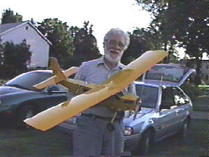
The August and September Meetings, or How I Fell In Love with the X440!
 |
Both the August and September flying meetings were very well attended, as you
can see in the pictures. Flying was the order of the day. The weather cooperated both meetings - amazing. The September
meeting was plagued with a few unexplained crashes. It was really nice to see Ernies Amptique back in flying form, after the
servo failure that took it down in August.
In the first photo, Don Skiff shows off his really nice
"original" design. Look for more details in next month's Ampeer.
I had a great time with the SR Batteries' X440. Richard Utkan, put
the whole thing together, since he had the power system and radio and the time. My only input was the beautiful kit. |
Once we got it into the air, it was electric elation!!! It uses the least expensive recommended power system, and has more power than
necessary to just laze around, and that is what this plane does extremely well. Without even trying, and while walking up and down the flight line talking to members about everything else, I easily flew for over 20 minutes on 7 Sanyo 600AE cells. This was
not thermal soaring, just a few motor on/motor offs and lots of my talking and flying at a very low power setting. Test, approved
and highly recommended. Be aware that you do need a radio that will allow rudder and elevator mixing. Go for it!!!
A typical sight at the site, looking up into a lovely evening sky as we enjoyed the
evening with good friends, great weather and lots of flying. That's what its all about. Ah summer, a fond memory, but just think,
in a few months it will be spring. Yeah, right! Build, build, build. |
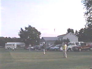 |
Helpful hint for next year: Don't run into the trailers, they're made of steel - right
guys!
Return to "What's In This Issue?"
Upcoming Events:
November 2, 10 Annual Midwest R/C Swap Shop, Northville Community Center, Northville, MI - on
Main Street, just west of Center St., Admission $3, Tables $12, for info: Herb Judd 248-477-0349 or Ray Whitney
313-591-9314
February 13, 14, 15, 1998 - THE SAN DIEGO WINTER ELECTRICS -- Equipment manufacturers and
vendors are invited to display their latest achievements. For details, e-address-
info@sefsd.org
Return to "What's In This Issue?"
Next Meeting: Thursday, November 6, 1997, 7:30 @ Dublin Community Center, which is
just north of the village of Union Lake, on Union Lake Road.
To Reach Ken Myers, you can land mail to the address at the top of the page. My E-mail address
is:
KMyersEFO@aol.com EFO WEBsite: http://members.aol.com/KMyersEFO/
Return to "What's In This Issue?"