 |
Flying High With Electric Power!
The Ampeer ON-LINE!
Fly the Future - Fly Electric! |
Site Table of Contents
| President: | Vice-President: | Secretary/Treasurer: |
| Ken Myers | Richard Utkan | Rick Sawicki |
| 1911 Bradshaw Ct. | 240 Cabinet | 5089 Ledgewood Ct. W. |
| Commerce Twp., MI 48390 | Milford, MI 48381 | Commerce Twp., MI 48382 |
| (248) 669-8124 | (248) 685-1705 | 248.685.7056 |
 | ||
| Board of Directors: | Board of Directors: | Ampeer Editor |
| David Stacer | Jack Lemon | Ken Myers |
| 16575 Brookland Blvd. | 8908 Sandy Ridge Dr. | 1911 Bradshaw Ct. |
| Northville, MI 48167 | White Lake, MI 48386 | Walled Lake, MI 48390 |
| 248.924.2324 | 248.698.4683 | 248.669.8124 |
| Mailed Ampeer printed subscriptions are no longer available. The Ampeer is FREE on-line in Acrobat .pdf format and HTML with active links! | ||
| The Next Flying Meeting:
Date: October 2 Time: 10:30 a.m. Place: Midwest RC Society 7 Mile Rd. Flying Field, Salem Twp., MI | ||
|
You can contact Bob Kopski regarding the BDM information in the September Ampeer at kopskib@gmail.com. I would appreciate a CC when you do - Ken The 26th Edition I am sharing the following so that all of the folks who made the 2010 Mid-Am a huge success know that all of their hard work was very much appreciated. Guys and Gals, this is for you. Keith and I can never truly express our gratitude to you. Without your volunteering, this meet could never be. We appreciate your efforts more than you can ever know!
Hi Ken, Tom and I want to thank you for setting us under your tent at the Mid-Am last Saturday.
Thank you,
To Beagle and all those others who couldn't make it to Mid-Am this year...you missed the best one in quite a while. Perfect weather, beautiful models, great pilots, and great company. Many thanks to Ken, Keith, and everyone else who make this great event possible. It's always the highlight of my RC season. Can't wait till next year. Mark Wolf Good times, great weather, new friends, old friends.
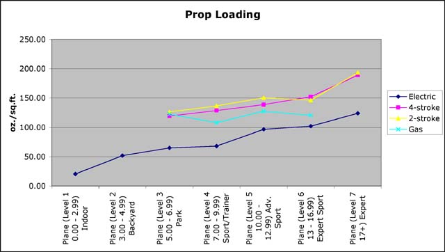
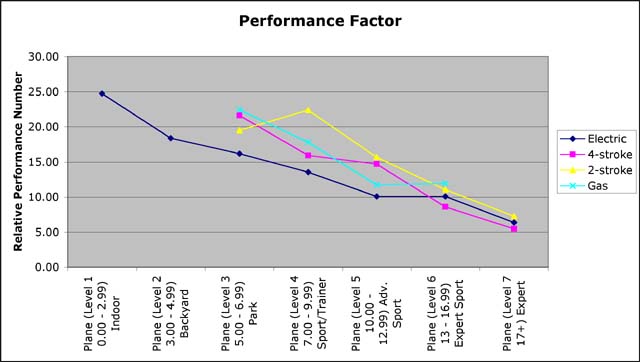
Denny Sumner Ahhhhhhhh... Maybe not, then again? KM The Flying Fosses had fun, thanks Ken, Keith, CJ, etc...... for a great meet. Pete, Carolynn and Sam Again folks, thanks so very, very much for making this a great Mid-Am! KM From Henry Holcomb Publisher/Editor At www.electricflyermagazine.com you'll find our online Electric Flyer Magazine. If you would kindly call this to the attention of your members we would be sincerely appreciative. By Ken Myers The first part of this article appeared in the August 2010 Ampeer and was titled "Comparing Glow Engines to Electric Power - Again". All of the data points in the graphs are AVERAGES for each of the wing cube loading (aka cubic wing loading/CWL) Levels. Keep in mind when viewing the graphs that the "outlying" levels have fewer data points, so the numbers in Levels 1, 2, 6 & 7 may or may not be accurately represented. A spreadsheet with all of the data that I've collected is available at www.theampeer/new-power-theory/metricnewtheory.xls. |
|
The higher the prop loading the smaller the diameter of the prop will be for a given weight. Prop diameter is a major determinate of thrust. Other factors like RPM and pitch do play noteworthy roles in determining thrust, but diameter dominates. The perceived performance of a model is based on two factors: its pitch speed to stall speed ratio and its thrust to weight ratio.
SQRT(((152/107.86)*144)/Pi)*2
For those who like to play with math, the other average prop loading numbers for CWL Level 4 are; 4-stroke 128.68 oz./sq.ft., 2-stroke 136.66 oz./sq.ft. and electric 68.05 oz./sq.ft.
|
|
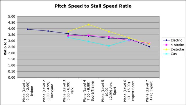
Overall the 2-stroke glow engine has a higher pitch speed to stall speed ratio at each Level. Electric motor power systems and 4-stroke glow systems are quite similar in their pitch speed to stall speed ratios. Once again there is an interesting "dip" at Level 5 for gasoline-powered systems.
|
|
From Gary Gullikson ggullikson@socal.rr.com I just got my Hitec 2.4GHz module and first Optima 6 receiver for use with my Eclipse 7 transmitter. Haven't bound and tried it yet. I cannot believe that the Hitec USA team did not proofread and make the instructions more understandable. I wonder if the Asian language versions are any better. Maybe the factory folks don't deign to talk to the US folks who must explain their terrible instruction sheets.
I have been flying a GWS ME-262 with two 2028 3900K brushless motors. If I fly too long or have to go around another time before landing, one motor may shut down before the other due to one speed control's LVC circuit acting before the other. When this happens the other speed control sees sufficient voltage and keeps running full tilt. This can result in a crash due to asymmetric thrust if I don't chop throttle fast enough and regain control for a dead stick landing. I found out that Dimension Engineering's "Smart BEC" has it's own LVC circuit that will over-ride the two speed control's LVC circuits if they are both speed controls are set for NiMH cutoff. I haven't had a chance to try this yet but attached is my crude diagram based on advice from Dimension Engineering and Castle Creations and the guru's on RCGroups. If this works it would also apply to twin motor twin speed control propeller models such as B-25's, etc. Probably could be expanded to 4 motors, etc. Maybe Keith Shaw or others might have some thoughts about this. (Note: Unfortunately, Gary's diagram didn't resize very well, and it is not reproduced here. Please send him email if you'd like his diagram. KM) I am a true believer in using switching-type BECs when using amp hungry 2.4GHz receivers and more than 3 servos I think that the hobby industry has been reticent and slow in informing users about the need for using switching type BECs.
Gary Gullikson, "E-Challenged" More Mid-Am Thanks & Other Related Topics Ken, I had a great time again at the Mid-America and the weather was fantastic. I flew my foamies; 2 birds and a wing. The real birds were chasing them all the time, so they may look like birds after all. I mentioned this in a post at the dirty birdy thread, (www.rcgroups.com/forums/showthread.php?t=1020550&page=11) together with some photos.
Phil Alvirez, Windsor, Ont., Canada Thanks Ken. It's sad the Mid-Am only comes once a year!
Ken, Bob Livin and I had a great time at the Mid-Am. We did no damage to our models, which for a couple of old geezers is not bad.
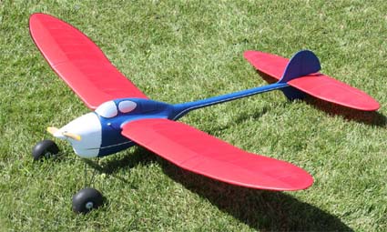
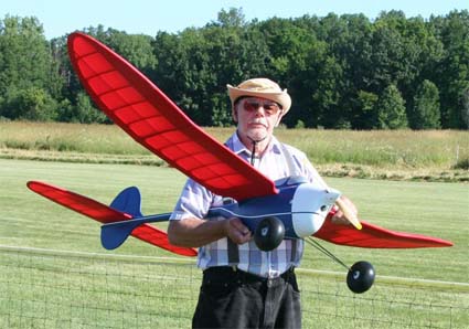 Here is a little about the Thermaleer that you used as the Mid-Am teaser photo in the August Ampeer. W.S.: 76"
All of the old timers have too much dihedral so Bob took a bunch out and it turned out the plane was difficult to control. So he bit the bullet and took the turtle deck over the wing apart and increased the dihedral. It now flies fine. The covering is a Polycarbonate Coated Ripstop Polyester. It is sold by Hang em'High.
ecom.citystar.com/hang-em-high/ushop/index.cgi
 He also designed the rubber powered Cruiser. From an AMA history document submitted to the AMA in 1997 by Hank Cole.
Plenny Bates A Strange "A123" 2300mAh Occurrence
I took the Super Stearman and the Flite 40
(www.rcgroups.com/forums/showthread.php?t=735972)
to the flying field on the evening of August 12. I "normally" charge my "A123" 2300mAh batteries before leaving the field after a flying session, so they are stored charged. To double check that I follow my normal procedure with a pack, I put them on charge on my CellPro 10S at the field before flying and take a peek at the numbers. The CellPro 10S reported a cell count error on the Flite 40's 6S "A123" 2300 pack. It would not charge the pack. I kept trying to get the pack to charge so that I could see the numbers. I thought that the 'hacked' 7-pin balance plug was not working correctly. The 88-deg+ heat and sun caused me great frustration with repeated tries.
Paul let me borrow his AstroFlight 109 with the "A123" mod in it. It reported that it was trying to charge a 7-cell pack. I stopped the charge and we used Paul's voltmeter and measured over 26 volts with no load. What? No way! A fully charged 6S "A123" 2300mAh pack should only be about 22 volts.
Bob Kopski's BDM & Some "A123" Info
Hi Ken, Came across your excellent Ampeer Magazine on the net and was intrigued by Bob Kopski's article describing his Battery Discharge Monitor and would like to build one (I'm a retired Electronics Engineer). Could you please arrange to have build details emailed to me as offered in the text - I couldn't find Bob's email address. I have been tinkering with a similar project and have been using a Hall Effect current sensor. Oops, sorry about that! Bob can be reached at kopskib@gmail.com I'm also a fan of A123 batteries and have several planes powered by them - some of the packs have been in use for 3 years and are still going strong. 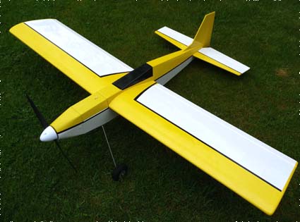 I have attached pictures of my latest plane. It's supplied as a kit (balsa sheet etc) by SLEC here in the UK - it used to be a Precedent Fun Fly (Wingspan is 52") before SLEC kitted it. The plane was intended for IC, but we don't want to do that do we? The A123 battery pack fits nicely in the fuel tank compartment. 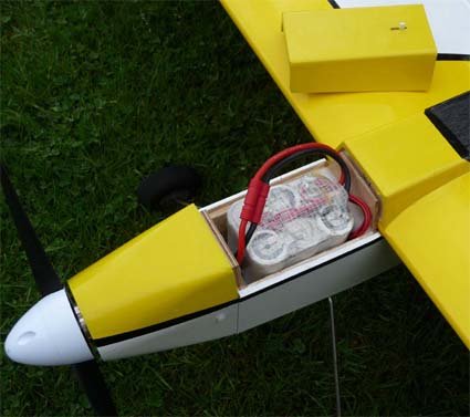 The motor is a Turnigy SK4250-650, powered by a 6S1P A123 pack, which produces 575 Watts @ WOT with a 12 x 6 EMP prop. (9660 rpm @ 17.63V and 32.6A). It gives me about 5>6 minutes of 'spirited' flying.
Incidentally, using the drill press method, the measured Kv of the SK4250-650 was 603 rpm/V, not 650 as claimed on the data sheet.
Best wishes,
A Problem with FMAdirect Adapter Boards Discovered
Joe Hass of the Skymasters' RC club contacted me about a problem that he had had with an FMAdirect Adapter Board for the CellPro 10S. His charger had stopped working, so he sent it in to FMAdirect for repair. They contacted him and asked how/why the traces on the PCB adapter board became charred. He had not noticed it and had no idea.
 I am not familiar with other companies' similar boards, but I would suspect that they have a similar problem as they are all made, most likely, in a similar fashion.
Horizon Hobby is Possibly Selling 72MHz Transmitters that are NOT in Compliance with USA FCC Regulations
At the PMAC electric fly-in I had an unfortunate incident with my parkzone ZX10 5-Chan FM 72MHz transmitter for my parkzone T-28. I dropped it on its face while loading it into the car and broke the throttle/rudder stick clean off. Rather than trying to get it fixed, I ordered a new transmitter of the same type on August 8 from Horizon Hobby. I ordered it on Ch 54 to match the receiver IŐm using in the T-28. I already had one of the parkzone ZX10 5-Chan FM 72MHz transmitters on Ch 17 that I use as the buddy box (with the crystal and antenna removed) for my student pilot training using the T-28 and on another trainer, the Fledgling, with a Spektrum DX-5e.
The new transmitter arrived on Monday, August 16. To my surprise, it was on Ch 17 although my invoice clearly showed that I had ordered Ch 54.
I have reprinted part (b) of Sec. 95.645 below and used a bold font to point out the section that specifically excludes crystal swapping by the end user. COMMISSION (CONTINUED) PART 95--PERSONAL RADIO SERVICES--Table of Contents Subpart E--Technical Regulations Sec. 95.645 Control accessibility. (b) An R/C transmitter which incorporates plug-in frequency determining modules which are changed by the user must be certificated with the modules. Each module must contain all of the frequency determining circuitry including the oscillator. Plug-in crystals are not considered modules and must not be accessible to the user. Obviously the ZX-10 transmitter is in violation of part (b).
frwebgate.access.gpo.gov/cgi-bin/get-cfr.cgi?TITLE=47&PART=95&SECTION=223&YEAR=2000&TYPE=TEXT COMMISSION (CONTINUED)
(a) You must not make or have anyone else make an internal modification to your R/C transmitter. I did not receive an instruction manual with either of the two transmitters that I'd purchased separately from the T-28.
frwebgate.access.gpo.gov/cgi-bin/get-cfr.cgi?TITLE=47&PART=95&SECTION=653&YEAR=2000&TYPE=TEXT COMMISSION (CONTINUED) PART 95--PERSONAL RADIO SERVICES--Table of Contents Subpart E--Technical Regulations Sec. 95.653 Instructions and warnings. (a) A user's instruction manual must be supplied with each transmitter marketed, and one copy (a draft or preliminary copy is acceptable provided a final copy is provided when completed) must be forwarded to the FCC with each request for certification.
All of my other 72MHz transmitters have an FCC ID number on them. The parkzone transmitters do not. With no FCC ID number and no instruction manual I believe that these transmitters may not be type certified by the FCC. I have NOT verified this by contacting the FCC to check the certification. It is a guess on my part. frwebgate.access.gpo.gov/cgi-bin/get-cfr.cgi?TITLE=47&PART=95&SECTION=603&YEAR=2000&TYPE=TEXT COMMISSION (CONTINUED) PART 95--PERSONAL RADIO SERVICES--Table of Contents Subpart E--Technical Regulations Sec. 95.603 Certification required. (b) Each R/C transmitter (a transmitter that operates or is intended to operate at a station authorized in the R/C) must be certificated, except one that transmits only in the 26-27 MHz frequency band and is crystal controlled (where the transmitted frequency is established by a crystal (a quartz piezo-electric element)). I was going to quote what can happen if the FCC rules for RC are violated but you can look them up at: frwebgate.access.gpo.gov/cgi-bin/get-cfr.cgi?TITLE=47&PART=95&SECTION=218&YEAR=2000&TYPE=TEXT During my discussion with the lady at Horizon Hobby support, I briefly pointed out that it appeared to me that the transmitter being handled this way was not in compliance with the FCC regulations. She sent me a prepaid RMA for the return of the transmitter.
I now have my T-28 back into the teaching rotation and feel good about doing it the "right way." |
To Reach Ken Myers, you can land mail to the address at the top of the page. My E-mail
address is:
KMyersEFO@theampeer.org
EFO WEBsite