 |
Flying High With Electric Power!
The Ampeer ON-LINE!
Fly the Future - Fly Electric! |
Site Table of Contents
| President: | Vice-President: | Secretary/Treasurer: |
| Ken Myers | Richard Utkan | Rick Sawicki |
| 1911 Bradshaw Ct. | 240 Cabinet | 5089 Ledgewood Ct. W. |
| Walled Lake, MI 48390 | Milford, MI 48381 | Commerce Twp., MI 48382 |
| (248) 669-8124 | (248) 685-1705 | 248.685.7056 |
 | ||
| Board of Directors: | Board of Directors: | Ampeer Editor |
| David Stacer | Jack Lemon | Ken Myers |
| 16575 Brookland Blvd. | 8908 Sandy Ridge Dr. | 1911 Bradshaw Ct. |
| Northville, MI 48167 | White Lake, MI 48386 | Walled Lake, MI 48390 |
| 248.924.2324 | 248.698.4683 | 248.669.8124 |
| Mailed Ampeer subscriptions are $10 a year US & Canada and $17 a year world wide. FREE on-line! | ||
| The Next Meeting: Date: Saturday, Sept. 8 Time: 10:00 a.m. Place Midwest 7 Mile Rd. Flying Field | ||
|
Ken Myers 1911 Bradshaw Ct. Walled Lake, MI 48390 Phone: 248-669-8124 Ampeer Paper Subscriber Reminder When subscribing to or renewing the paper version of the Ampeer, please make the check payable to Ken Myers. We do not have a DBA for the Ampeer or EFO. Thanks, Ken By Ken Myers - August 2007 Last month I talked about the ESC (electronic speed control) and how advancing or reducing the timing affects the "motor parameters", so the question is, how do you select an outrunner brushless motor for a given project when few of the suppliers of brushless outrunner motors give the data required to make a rational selection?
Since I am extremely "high" on the M1 (A123 Systems) cells, manufactured by China BAK, for sport and sport scale planes, I wanted to find a project that would use these cells, so I am starting with the battery selection first. I'll start with a five-cell project. Why five? It allows me to "harvest" two 5-cell packs from a DeWalt 36v (DeWalt DC9360) pack for between $100 and $125 if purchased and shipped from an ebay provider, making the cost of each pack in the $60 range. I have been having great success using M1 cells at a maximum of about 35ish amps static at wide-open throttle (WOT). Seven-minute flights are the norm for my Fusion sport plane (electroflying.com/fusion.html) with an extra minute for go-a-rounds if necessary. The recharge time with my AF109 (unmodified, when charging my 6-cell pack at 7.45 amps) has been between 18 minutes and 22 minutes. The voltage from the pack using a 35 amp maximum static load for these cells averages about 2.85v per cell, thus when used in this way, a single cell equals about 100 watts in for the way I want to use them. A 5-cell pack, for me, would be putting in about 500 watts. The type of plane being discussed here is NOT a park flyer. It is one that will be "mixing it up" with glow planes at the RC flying field. It will be taking off and landing on grass. Using about 100 watts in per pound usually yields a plane that will give no quarter, or get in the way of the majority of glow planes buzzing around the field. (Next month I'll reverse this process and start with the plane, as I have just received a new one.) Weight Allowances: Using about 100 watts in per pound means that the plane should weigh somewhere around 80 oz. (5 lb.) ready to fly (RFT). The 5-cell M1 battery with balancing leads, shrink-wrap and Velcro should weigh about 14 oz., based on the weight of my current 6-cell pack. The weight for a brushless outrunner consuming 500 watts in tends to be between 1.5g of motor weight per watt in, which is on the heavy side to 3g of motor weight per watt in, which is on the light side. Heaviest: 500 / 1.5 = 333g (11.75 oz.) Lightest: 500 / 3 = 167g (5.9 oz.) Midpoint: 500 / 2.25 = 222g (7.84 oz.) The prop adapter, motor mount, prop, mounting hardware, etc. can add another 30% of the motor weight to the total installed motor weight of this size project. Using the Midpoint weight plus another 30% of that weight plus the battery weight, the power system weight might be between 24 and 25 ounces. It could also be up to possibly 4.5 ounces heavier if the "heaviest" motor is used. I have found that, on average, for these types of planes, the onboard radio system weight is about 12.5% of the total weight. With 80 ounces as the maximum target RTF weight, that means about a 10 oz. onboard radio system. That weight includes the receiver, switch harness, ESC (electronic speed control), servos, servo extensions, push rods, control horns, plywood used to mount the servos and onboard receiver battery. The completed airframe weight includes the weight of everything not already mentioned to complete the project. The maximum completed airframe weight of this project should not exceed; maximum target weight of 80 oz. - 25 oz. power system - 10 oz. radio system or about 45 ounces if the actual power system and radio weights are close to those mentioned above. 40 ounces for the completed airframe weight would give a bit more "wiggle" room, with anything lighter being a real plus. Sport/Sport Scale planes have a cubic wing loading (CWL) range of 7 oz./cu.ft. (extremely light bordering on a park flyer) to 10 oz./cu.ft. and Advanced Sport/Sport scale planes have a CWL of 10 oz./cu.ft. to 13 oz./cu.ft. I have collected quite a bit of data on these types of planes and the average CWL for Sport/Sport scale planes using an outrunner motor is 8.47 oz./cu.ft., while the average CWL for Advanced Sport/Sport scale is 11.44 oz./cu.ft. To find a suggested wing area for the maximum target weight 80 oz. plane I used the averages. Sport/Sport Scale 80 oz. / 8.5 oz./cu.ft. = 9.41 cu.ft. ^ (0.6666667) = 4.46 sq.ft. * 144 = 642 sq.in. Advanced Sport/Sport Scale 80 oz. / 11.5 oz./cu.ft. = 6.96 cu.ft. ^ (0.6666667) = 3.64 sq.ft. * 144 = 525 sq.in. Note: 0.666667 is the inverse of 1.5 which is used to find the cubic feet for the cubic wing loading I have talked about previously. Finding planes that meet the above criteria is not really easy. Most kits and ARFs that have been designed for glow motor use are too heavy to meet the maximum airframe weight of only 45 oz. My first choice would be the ElectroFlying Fusion. I have one and have been flying it for a few years now. It is a kit and requires the modeler to build it. The reward for the modeler's effort will be one of the very best flying 569 sq.in. sport planes ever! A little research shows that these glow kits might work as well. Great Planes Dazzler 40 Kit .32-.46, Wing area: 578 sq.in., Weight: 3.5-4 lbs (Tower Hobbies) Sig Somethin' Extra Kit, Wing Area: 614 sq.in., 4.3 to 4.8 lbs. (Tower Hobbies) Sig Four-Star 40 Kit, Wing Area: 604 sq.in., Weight: 4.75 lbs (Tower Hobbies) These are a few possible ARF type planes. Great Planes Super Sportster 40 MkII ARF, Wing Area: 555 sq.in., Weight: 4.75-5 lbs (Tower Hobbies) Sig Four Star 40 ARF (Red or Yellow), Wing Area: 604 sq.in., Weight: 4.75-5.25 lb. It should be noted that when doing a glow conversion it is actually better to use a motor towards the heavier end of the range noted above, as it makes balancing the plane much easier, and it won't be working as hard as a lighter motor. Prop Selection: Diameter Over the years, I have found that I personally prefer a prop disk loading of between 75 oz./sq.ft. and 120 oz./sq.ft. for my sport and sport scale planes. If a lot of math using the area of a circle is too much for you, you can just use a prop disk factor (PDF) to get a suggested prop diameter range. The PDF for a prop disk loading of 120 oz./sq.ft. is 1.2 and for a prop disk loading of 75 oz./sq.ft. it is 1.92. That makes the math a whole lot easier than working with the area of a circle and minimizes the steps. My minimum personal prop diameter = Square root ((80 oz. target weight * PDF 1.2 )/ Pi) * 2 = 11.06 in. or 11 in. My personal maximum prop diameter = Square root ((80 oz. target weight * PDF 1.92) / Pi) * 2 = 13.98 in. or 14 in. In general, typical sport/sport scale planes have a pitch speed ((RPM * pitch in inches)/1056) between 50 mph and 70 mph. Battery: 5-cell M1 pack Maximum RTF target weight: 80 oz. (5 lb.) Wing area: 525 sq.in. to 650 sq.in. Maximum Completed Airframe wt: 45 oz. Onboard radio system wt: 10 oz. The ESC must be able to handle 35 amps continuous with a "safety" margin, therefore at least one rated for 40 amps continuous and 18 volts (fully charged resting voltage of an M1 cell is 3.6v * 5 cells = 18 volts). Prop: Diameter 11 in. to 14 in. Pitch & RPM to equal pitch speed between 50 mph and 70 mph, with 55 mph to the low 60s being the "norm." Motor: Weight 167g to 333g It must be capable of handling 500 watts in continuous at 35 amps continuous. Please forget the burst nonsense for sport planes. Selection of an appropriate motor could not be easier. Since a good, appropriately sized 4S Li-Po pack at a 35 amp static load supplies about 14v to the ESC, looking at the manufacturer or supplier prop data for a 4S Li-Po or about 14v makes the selection process very simple. Kept in mind that the 5-cell M1 pack will be supplying a bit higher voltage (14.25v under 35 amp load) and therefore the amp draw will be a little higher as well, but still a 4S Li-Po, because it is so common now, is a good guide. Atlas: 2927/10, 198g, Kv 740, (no prop-voltage-amperage data) AXI: Note: Unfortunately all of the prop-voltage-amperage data on the Model Motors Web site for the AXI 2826/12 and AXI 4120/14 is for folding props, which I do not use. Also, I have found no sites selling AXI motors that have tested fixed props for these motors and posted the results. They simply repeat the information provided by Model Motors. Fortunately, Drive Calculator has quite reliable data for these motors. The DC data follows: 2826/12, 181g, Kv 760, APC 12x6 sport, 9000 RPM, pitch speed 51 mph, APC 11x8E or sport, 9000 RPM, pitch speed 68 mph 4120/14, 320gm, Kv 660, APC 12x7 sport, 8700 RPM, pitch speed 58 mph, APC 13x6 sport, 8600 RPM, pitch speed 49 mph BP Hobbies: A4120-7, 298g, Kv 610, (no prop-voltage-amperage data) www.bphobbies.com/view.asp?id=V450327&pid=B2171400 E-flite: Power 32 BL, 200g, Kv 770 (no prop-voltage-amperage data) www.horizonhobby.com/Products/Default.aspx?ProdID=EFLM4032A Unfortunately, the data on the Horizon Hobby Web site for the Power 46 BL is all at much higher amp draws than desired for this project. Fortunately, Steve Neu reviewed this motor and I was able to use his data to create a Drive Calculator virtual version. The Drive Calculator data is presented after the basic supplier data. Power 46 BL, 290g, Kv 670, APC 12x6 sport, 8800 RPM, pitch speed 50 mph Hacker: A30-12XL series, 179g, Kv 770 (unsuitable amp draw on the 12-turn) hackerbrushless.com/motors_a30.shtml A40-10S, 265g, Kv 750 or A40-12S, 265g, Kv 610 (no prop-voltage-amperage data) hackerbrushless.com/motors_a40.shtml Note: There is no link from the US Hacker site (www.hackerbrushless.com) to the prop-voltage-amperage data for Hacker motors, but it is available on the German site. This link will bring up the prop-voltage-amperage data for the A30-12XL mentioned above: www.hacker-motor.com/deutsch/A30-12XL-Messwerte.pdf Himax: HC3528-800, 197g, Kv 800, unknown 13x9 (no prop-voltage-amperage data) www.maxxprod.com/mpi/mpi-262.html and www.maxxprod.com/pdf/HC3528-0800.pdf Hyperion: Z3025-12, 186g, Kv 665 (According to the prop-voltage-amperage data posted on the Web site, this might work.) APC13x6.5E, 4S, 38 amps, 7980 RPM, 550 watts in APC12x6E, 4S 30.5 amps, 8540 RPM, 435 watts in aircraft-world.com/prod_datasheets/hp/z30/z3025spec.htm Propping to 35 amps might be something like an APC 12x7 sport at about 8700 RPM which would yield a pitch speed of 57 mph, but this is only a guess. Z4020-12, 284g, Kv 660 (no prop-voltage-amperage data) aircraft-world.com/prod_datasheets/hp/z40/z40all.htm HXT: 42-50-A, 195g, Kv 678 or 600 (contradicting data on Kv) 12x8 APC-E (4 cells: 32A, 450W, 1690g, 59mph, 7800rpm) 13x8 APC-E (4 cells: 39A, 547W, 2050g, 57mph, 7430rpm) While there is not enough data to do a virtual version of this motor in Drive Calculator, it can be seen that this motor might work with props in-between the two noted in the data above. www.unitedhobbies.com/UNITEDHOBBIES/store/uh_viewItem.asp?idProduct=4911 42-63, 298g, Kv 646 or 600 (no useful prop-voltage-amperage data) www.unitedhobbies.com/UNITEDHOBBIES/store/uh_viewItem.asp?idProduct=2098 Scorpion: 3026-12, 189g, Kv 840 innov8tivedesigns.com/Scorpion/Scorpion%203026-12%20Specs.htm Using the prop-voltage-amperage data chart it looks like an APC 11x5.5E might work and have the appropriate amp draw, watts in and pitch speed, but the Kv is pretty high for this group. APC11x5.5E, 10175 RPM, pitch speed 53 mph 3032-12, 224g, Kv 687, (no prop-voltage-amperage data) www.innov8tivedesigns.com/product_info.php?cPath=21_25_38&products_id=83 TowerPro: Note: the TowerPro site and BP Hobbies site have no useful prop-voltage-amperage data for the 3520-6 or -7. Also, the BP Hobbies site has no useful prop-voltage-amperage data for 35 amps and the appropriate prop diameters. Fortunately, I have both motors in hand and have added the data to Drive Calculator, which is presented below: 3520-6, 262g, Kv 725 APC 11x7E, 9500 RPM, pitch speed 63 mph, APC 12x6E, 9300 RPM, pitch speed 53 mph 3520-7, 262g, Kv 615 w/ 1-deg timing, APC 12x10E, 7500 RPM, pitch speed 71 mph, APC 13x8 E or sport, 7500 RPM, pitch speed 57 mph Welgard: C4250-7, 203g, Kv 695, (no prop-voltage-amperage data) www.bphobbies.com/view.asp?id=A2586784&pid=A3548004 Note: While the BP Hobbies site does not have useful prop-voltage-amperage data, there was enough data to enter the motor into Drive Calculator and get the following information. C5055-6, 301g, Kv 628, APC 12x8E or sport, 7800 RPM, pitch speed 59 mph I hope the reader can see how easy it is to select the proper motor based on the manufacture or supplier data. NOT! Is it any wonder that we have to turn to motor/battery/prop calculators like MotoCalc, ElectriCalc or Drive Calculator to help us make a reasonable, rational motor choice? As consumers, I believe we should expect the manufacturer or supplier to give us real world, really useful information and more importantly, keep that information up to date! Here is just one example of out-of-date data showing up and being used for current production motors by suppliers. I am NOT picking on AXI! It is just one really bad example I am personally aware of. Many folks selling the AXI line of outrunners use this link to a review to base their promotion and selling of the current version of the AXI 2820/10, www.rcgroups.com/forums/showthread.php?t=194098. The review was written by Steve Horney in 2002. A quick check of the photo image in the review and the motor specifications quickly reveals that this is NOT the current production motor by Model Motors modelmotors.cz/index.php?page=61&product=2820&serie=10&line=GOLD. Also, the prop/battery data on the above noted Model Motors page is NOT for the current production version. Yet, it is still there for all to see! The table is based on NiCad technology and was done when the motor had a Kv closer to 1100 RPM/v (If memory serves me right MM published the Kv at that time as 1087 RPM/v) than the current 1200 RPM/v, yet there is no note about this being "old" data. The chart was also done before APC changed the design of its thin electric (E) props to the current production versions. While this motor has no direct application to the project being discussed here, it shows how absolutely unreliable published data can be when it is not kept up to date. Is there any hope? Maybe. Lucien Miller (AKA LBMiller5 on RC Groups) is importing and supplying the Scorpion brand of outrunners to the hobby market. He is testing prop-voltage-amperage combinations for all of the motors he is marketing. This is a HUGE task, but he seems to be willing to go the extra mile to do it. I congratulate him for "doing the right thing!" Unfortunately, for this particular project, he has not published the data for one of the motors that might have worked, the 3032-12, although I believe the Kv might be too high, but his prop-voltage-amperage test would have confirmed that. The data on this motor may be posted by the time you read this. Ultimately, my only logical choice is to use the TowerPro 3520-6 or -7, depending on prop clearance for the particular model. It is not better than any of the others, and might actually not be as "good" as several of the other choices, but the data is available because I collected it! The -6 will work with 11 and 12 inch props when pulling 35 amps and the -7 will work with 12 and 13 inch props with appropriate RPM to deliver the desired pitch speed. The TowerPro 3520 is heavier than some of the other choices, but that can actually be a plus if doing a glow conversion of the planes mentioned above. Several times in the past I have gambled on supplier data and purchased the wrong motor for the task. I have a perfectly good, almost as good as new, Hyperion Z3019-10 that still sits unused because it draws too much current for the prop I wanted to use with it for a given project (APC 11x7E, 9.28v, 48.1 amps as tested). The prop-voltage-amperage data on the Aircraft World Web site does not reflect the real world measurements of the product I received. I also purchased an AXI 2820/10 that threw a magnet and a deal was worked out with Hobby Lobby for the return of the motor in which I received the AXI 4120-18 that is used in my Fusion for a bit more money. The 2820/10 never ran anywhere near the prop sizes listed on the AXI site at the posted amperage draws and was a discussion topic on RC Groups for quite a while. The first TowerPro 3520-7 I purchased turned out to be a -6, which is now used in my Ryan STA, but not the motor that I wanted at the time or thought that I had ordered. That confusion now seems to be taken care of by some of the suppliers, but others may still send you a -6 when you order the -7. So where are we now? I recommend the TowerPro 3520-6 or -7, for this type of project, not because it is good or better than any of the others, but NONE of the other suppliers'/manufacturers' data can be trusted. This motor is good enough, and I personally know it will work. I also recommend that you keep an eye on the Scorpion line of motors, as Luicen seems to be trying to give us the useful information we need on a product that looks very promising. Have fun on FIVE until next time! KATANA MD: Advanced Freestyle EP Model Review
Quick Specs:
Mike Southwood does a rapid build of this Almost Ready To Fly (ARF) Katana MD from Precision Aerobatics / FiberFusion. Designed in Australia.
If any model has convinced me that electric power can and will overtake glow engines, this one has. It is the first electric model I have flown which hasn't, as far as I can see, any disadvantages, and so many advantages. It is also a little depressing to find that after 60 years of model making, building mostly from scratch or kits, I can never compete with the quality of cutting, assembly and finish of this plane. Never will I be able to build a 48" span, good looking, strong, rigid and superbly covered plane weighing only just over 2 lbs. ready to take off. It does not get messy or change balance while the fuel runs out. It performs the same after idling around in a thermal for 10 minutes without the risk of the engine stopping. It can climb vertically until I can no longer see it, or idle around at walking pace. The box was collected from Al's Models along with a selection of other parts necessary to complete the model. It is, at least for me, a new type of construction incorporating extreme precision, laser cut ply and balsa parts, reinforced and braced with carbon fibre. The structure is very complicated, resulting in a rigid light plane designed from the start for electric power and Li-Poly batteries. 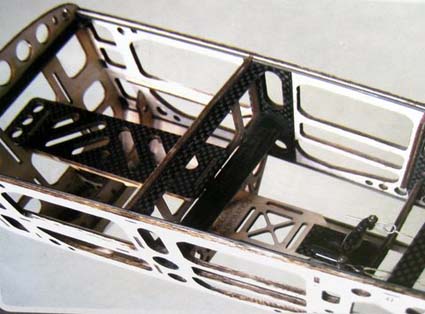
The construction can be clearly seen in this photo. All the covered parts were packed in the one large box, with a little polystyrene foam protection, but all in bags taped to the sides and bottom of the box. The bags were quite difficult to remove without damaging the bits. All the required fittings, screws, nuts and washers were bagged and taped in.
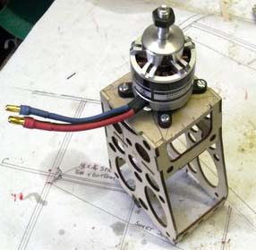
This is the most advanced design, certainly of construction and materials that I have, so far, experienced. Parts are mostly assembled from laser cut ply, but with bracing from carbon fibre rod sheet and tube. Every effort has been made to keep weight to a minimum, yet retain extreme rigidity. All of the laser cut parts interlock and are a perfect fit. Very little glue has been used and I found some joints came apart if pulled too hard. This is a problem with laser cutting by burning, leaving carbon on the joints which stops complete bonding with glue. The covering is something like ProFilm, with basic decoration; leaving it to you to apply extra transfers (supplied). Workmanship is excellent, although there was some slight wrinkling, which needed ironing out after completion. The fittings are of a high quality and included carbon fibre rods for linkages and carbon fibre sheet horns. Closed loop is used for the rudder. The undercarriage, consisting of two moulded legs, is also carbon fibre. They are light but strong. I was pleased to see that the whole undercarriage fitting was strongly braced back to several bulkheads with carbon fibre tubes. Motor mounting is a pre-made tower structure from laser cut ply. It is intended for the motor to be mounted inside, bolted to the front bulkhead with shaft poking through. Down and side-thrust are built in. I chose to use a Dualsky outrunner, which has a very nice prop driver and mounting cross plate. This could not be fitted inside the ply structure and a new bulkhead had to be made from birch plywood, jointed to the original mount after cutting back by the length of the Dualsky. In my case, the motor now bolts back to the shortened mount and hangs free in front. The prop driver bolts to the outrunner with five cap head screws. 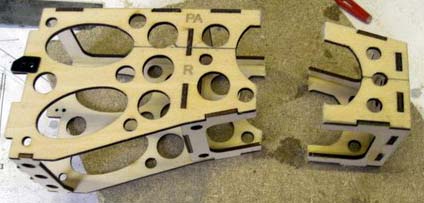
 The wings are in two panels, fitted to the fuselage with a carbon fibre spar tube and bolts through the side. The ailerons are beautifully hinged just like real planes with no plastic hinges and a very free and smooth action. Horns are carbon fibre, again high quality. Wheels are very light and thin, but inside the GRP spats they do not look too bad. MOTOR: DUALSKY XM3636CA 8 turn, 990 RPM/V, 350W Class .15 Propeller: APC 12x5SF Slow Fly. ESC: DUALSKY XC4018BA 40-amp. Li-Poly: Kong Power. KP-2225-3, 11.1v. 2200mAH, 25C Servos: PICO / NARO + FHP/BB/F Radio: Spectrum DX7 2.4 GHz. W/AR 7000 dual receivers The servos need extension leads or extending with extra wire and heat shrink. In my case I extended the leads. Also needed is a "Y" lead unless you use a 6-channel receiver (using 1 & 6 for ailerons) Connectors have to be purchased and soldered on to the ESC and Li-Polys. The 3.5mm gold tubular types were used. After removing the fuselage from its clear plastic bag, it was examined and checked to find no damage. The canopy was removed. Quite a pull was required as it is a perfect fit that is held down by four magnets and two pegs. The covering film was cut out as described in the instructions, using, in my case, a small soldering iron, which not only cuts through but also melts the edges and seals them to the wood. Fitting in the stabiliser and elevator was easy. It lined up well with the wing. Just remember that the elevator has to go in first, if you forget the elevator it will be impossible to fit without cutting a slot in the tail post. Hinges are all furry plastic, fixed in with superglue. No problems were found fitting the chosen GWS Naro servos. The one for the rudder had to have a supplied carbon fibre longer arm screwed to the top of the standard arm. A longer screw from the scrap box held the assembly on to its splines. After fitting the stabiliser, elevator and rudder, the gaps had to be sealed with clear tape ironed on, being careful to allow full movement of the surfaces. This is claimed to obviate flutter, which with the very large control surfaces and super lightweight, only powered by miniature servos, could prove a problem. I used cello tape for this job, because if there had been enough tape supplied as iron on film, I had lost it. The wings required no work other than fitting the servos. I elected to paint the servo recesses, just to look better after the servos were fitted. Because I was using a "Y" lead, it was decided to leave servo installation until the wings were bolted on. Later it proved easy to get the leads down into the rear hole of the servo boxes using a bit of bent wire and fishing them through. With everything assembled the servos were centred using a standard receiver and battery. Operating rods were then made up from supplied carbon fibre rods, which had one end, fitted with a Z bend. The second Z bend had to be bound and glued to the rod at the correct length to centre the surfaces. No adjustment is possible once made up. The rudder is operated by a Kevlar thread closed loop system. It's a bit of a fiddle getting the strings through and setting up the tension. For some reason the adjusting screws have to be underneath where one cannot get at them without removing the servo-operating arm. The big rudder appears to be quite floppy, but that is the proven design. Later I plan to use a larger rudder horn as the geometry results in too much movement and too much flexibility. Cutting down throw by using the transmitter loses some precision. The motor and complete mount had been previously modified to take the large outrunner, bolted back to a new bulkhead. This assembly was glued into its place, lots of tabs, perfect fit. I used white PVA for this and added a couple of triangular reinforcements. The cowl fitted perfectly, using the described method to mark fixing holes over the carbon fibre reinforced tabs. I elected to use a 1.5-inch spinner to finish off the front. (Not supplied) For the test flights, the chosen propeller was an APC 12x5SF Slow Fly. The Li-Poly used, a 2200mAh 11.1 volt, proved to be slightly too fat to pass through the opening over the tray, but a little work with a sanding drum on a Dremel type drill soon had it a perfect fit. I glued a piece of Velcro around the battery tray, to secure the battery for flying. Access to the connection is superb. The whole canopy and top deck come off forward to the cowl. All my connections used 3.5mm gold plated plug / sockets. The ESC was tie wrapped to the engine mount, inside the cowl. 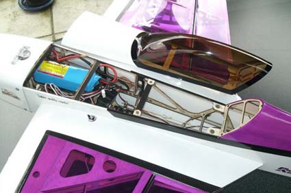
Radio: The main reason for buying this kit was the new technology of mixing carbon fibre, plywood and balsa. The result was looking so good that I decided to purchase a new radio set and chose the SPECTRUM DX7 2.4 GHz. Being a gadget lover and having experienced a few shoot downs in the past, I wanted to try the new technology. This SPECTRUM radio is obviously in a JR case and even has the reversed charger connection. There was no charger is supplied with my set. One has to be careful not to use an existing Futaba charger without changing polarity. The supplied digital servos are excellent, but too large for this plane. GWS NAROs fitted without any problems. I did use the rubber grommets, but am of the opinion that for an electric model, it is probably better to mount them hard in the bearers. Use a washer and a touch of silicon glue. The two receivers were stuck in with back-to-back foam pads. There was plenty of room. Aerials were set at right angles to give maximum coverage from all angles. My servo plugs had to have the tabs filed off before they would fit, but this was no problem, resulting in a neat and fairly light set up. The radio instructions look good at first sight, but fail to show simple connection detail, especially for the switch harness, i.e. which is the radio, charger and battery connection. Putting a label on the wires would help. As an aside, I mention that somewhere between the shop and my plane, I had lost the all-important Binding Plug. At least it made me clear up the workshop, but still no plug. A quick phone call to Horizon UK, promised a replacement in the post. I was also told that if I removed the centre pin and joined up the outer pins of a standard servo plug, it would do the job, so a special plug was made up with a long neck strap. Another question, not explained in the DX7 instructions was how to bind the set if one was not using the supplied switch harness. In this case the Li-Poly power gets to the radio via the ESC BEC and has no charging socket in which one should plug the binding plug. A quick query to the supplier resulted in the answer. Just plug the binding bit into the battery socket of the receiver and plug in the main Li-Poly. It worked! My next problem was programming. The DX7 is not easy, at least for me. I took a long time, armed with the instruction book, before I had allocated dual rate switches and set up rates and exponential as suggested in the Katana instructions. Saturday morning, only one day after starting assembly, we were ready to fly except for setting up the transmitter. Unfortunately, the wind was very strong and after a flight with a CAP 22 electric model, I decided not to risk the new KANTANA and live to fly another day. 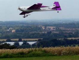 We finally had a half good day. There was bright sunshine, but the wind was very gusty and the in the wrong direction. Anyway, I decided to give it a try. The plane was aimed into the wind on the short grass and the throttle opened up. There was no problem. She took off in about 20 feet, climbing away at a very respectable rate on about half power. One click of right trim had her flying hands off and straight. Even in the gusty wind, flying was stable and not too difficult, despite very fast responses. After eight minutes of varied aerobatics, not 3D as that is not my scene, a landing was called and a nice slow approach made. One thing I found is that a little throttle is needed during the landing. In fact it is best left to land itself, just using throttle to sink or rise. With power off she stops very fast, but does not stall, just flops about. There was still plenty of power left, so another five minutes of flying occurred before bringing her in for a charge. With the meter and charger hooked up, she took 1283mAh to get back to full. Not bad for the flying done, in fact very good. For my second day of flying, I tried fitting the tiny 4.5-gram Park Flyer Receiver. It went in well and functioned after Binding (the term used by Spectrum to lock the radio to the plane). Unfortunately, a range check showed what I thought was poor range at about 50 feet with the test button held in. This was probably due to all that carbon fibre in the fuselage. Bench testing had shown about 90 feet. It was back to the full size receiver for now. All my flying has been done with the radio supplied as part of the DX7 set. Later flights have all been good. There are masses of power to climb vertically, but the plane is capable of flying around under full control on half or less throttle. The battery lasts about 15 minutes, although I have never run out of power yet. Charging usually takes about 1500mAh to fill, showing that a little weight could be saved by using a 1800mAh Li-Poly, but this might upset the balance and leave less reserve. With control surfaces set to low rates it can almost be a trainer, but with full power and high rates it becomes a very fast and responsive plane. This is a really well designed and manufactured model. For its size and wing area, it is very light but very rigid. The aileron hinges are a masterpiece, how they should always be, but seldom are. There were very few building problems. The only non-standard bit was modifying the motor mount to take the Dualsky 15 class motor. That added half an hour to the assembly, but apart from that it all fitted perfectly and looks superb. The actual build time was about eight hours. The Dualsky motor and ESC combination work well together, producing enough thrust to carry the weight vertically on about half throttle. It is very smooth and quiet. The combination of DX7 radio and GWS Naro servos also works well. The servos are fast to respond, although they are not overly powerful for such large surfaces. The complete lack of friction in linkages and hinges bodes well for flying. The one problem I foresee is when I crash. Note I say when, because this is such a good plane to fly and so responsive, it will eventually overcome my caution. Repairs will not be easy. The woodwork is weak without the carbon fibre and it is so rigid, a good crash will destroy it. More on M1 (A123 Systems) Cells
As previously discussed in the August Ampeer, I have one (of four) 4-cell pack of A123 cells wherein one cell had been showing signs of "falling behind" the other three. I indicated that I hoped to keep a closer eye on this situation, which I considered to be a fluke among my four packs total.
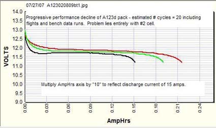 A DATAQ printout of the discharge behavior of the cells in the pack clearly shows that cell #2 is no longer good. I now officially declare this a "3-cell pack" and will eventually take out cell #2 and restack the pack to make it so physically. The only issue now is I don't have a "3 A123 cell plane". But that will eventually change, or something else will. Anyway, I still consider this a fluke situation in that, so far, none of my other A123 packs have shown a decline in flight. However, I'll be watching as time goes on. I still very much like the A123 Systems product. Regards to you and all your readers,
Upcoming EFO Meeting Info
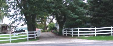
The photo above shows the entrance to the Midwest 7 Mile Rd. Field. It is the gate in the second white fence on the north side of the 7 Mi. Rd. 1.2 miles from Currie Rd. 7 Mile Rd. is closed just east of Currie Rd, therefore, 8 Mi. or 6 Mi Rd. must be used to reach Currie Rd. As you can see, it is a personal driveway of the property owner. Extreme caution and extremely slow speed is to be used on the entrance road. There are horses, cats, children and other people present. Pass to the left of the barn shown below to proceed with caution to the flying field. IMPORTANT! Channels 36 & 56 may NOT be used at this field! 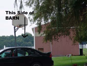 |
To Reach Ken Myers, you can land mail to the address at the top of the page. My E-mail
address is:
KMyersEFO@mac.com
EFO WEBsite: http://members.aol.com/KMyersEFO/