AKA The Generator Constant, RPM/volt, Annotated as Kv By Ken Myers Updated: November 2014 Ampeer Articles Relating to the Motor Constant Kv Finding R and K, December 1989 Motor Kv Question, January 2005 Measuring Kv Using the Drill Press Method, January 2009 It Is Not Just the Kv, May 2009 Ke variation, November 2010 (note: not a typing error; Ke is related to Kv) Identifying the Usefulness of an Unknown Brushless Outrunner, October 2011 Kv says nothing about a motors max.power, max.current and rpm Ron van Sommeren explains why Kv is not a rating. Reliable Information - NOT!!! An RC Groups thread started by Ken Myers on Oct. 22, 2014 after reading an article on the Model Airplane News Web site. Discussion of how people use the term for RPM/Volt (aka Kv) incorrectly. Tips for Getting Started with Electric Airplanes by Gerry Yarrish The article where RPM/Volt (Kv) is defined incorrectly.
Preface, November 2014
GENERATOR CONSTANT
Bob Boucher's book used no subscripts in any annotations, so I never have, and have always referenced the generator constant and torque constant as Kv and Kt respectively. I am not the only one with annotation errors regarding this motor constant. Various forms of annotating the letters k and v, placed side-by-side, abound on the Web and in printed materials. The best thing to do is use the context of the two letters together and note whether the author's intent was to reference the RPM/Volt generator constant. Some examples of the letters k and v together referring to RPM/Volt.
Kv is a motor constant and is directly related to Kt, the motor torque constant. Kv is most often expressed as RPM/Volt or RPM/v. Kt is often expressed in the units of inch ounces per amp. Kv (expressed as RPM/v) * Kt (inch ounces per amp) = 1352.4 (Note: Bob Boucher used 1355 as the constant.) The constant is used to covert SI (metric units) to inch ounces of torque per RPM.
Kv, the generator motor constant, is 'set' by the motor's physical makeup. The voltage used to multiply the Kv constant by, to determine the RPM, is NOT the input voltage at the motor for a brushed motor or the input voltage at the Electronic Speed Control (ESC) for a brushless motor. There is a voltage drop from the input voltage. The drop is caused by the resistance of the motor and its load for a brushed motor. For brushless motors, there are additional voltage drops caused by the resistance of the ESC, wire and connectors. V (volts) = I (current) * R (resistance)
The net voltage (Vnet) equals the input voltage (Vin) minus the current multiplied by the resistance (the voltage drop).
ALSO Vnet = RPM / Kv
As previously mentioned, Kv is also known as the generator constant or dynamo constant. When any electric motor's shaft is physically spun, it generates electricity. It doesn't matter whether it is a brushed or brushless motor. A typical hobby brushed motor can be spun by a drill press at a relatively constant speed. The DC voltage is measured across the terminals, with the brushes set to neutral timing. Using the known RPM of the drill press, the Kv, RPM per volt, can be calculated. i.e. 1560 RPM (known drill press RPM) / 1.6 volts (DC measured volts across the two terminals) = 975 RPM per volt. (To see how timing affects a motor, read Timing Test.) A brushless motor isn't quite as simple to test. A bit of math is required. Don't panic about the math. Download the Excel-based workbook and use the spreadsheet on tab Kv. A brushless motor has three possible lead combinations that need to be measured using the AC voltage setting on a multimeter. First, determine the constant drill press RPM (1545 in this example).
There are three possible combinations with a brushless motor.
REMINDER!!! The workbook spreadsheet (tab Kv) does all of the math. The following is only for the intellectually curious. Find the V-peak by multiplying the average AC volts by 1.414.
Brushless Kv formula using drill press
It should be noted that many manufacturers and suppliers, even the good ones, provide inaccurate information about a motor's Kv. Some of the inaccuracies are caused by individual variations introduced in the manufacturing process and some just by the manufacturer or supplier not knowing, or caring about, how to do it correctly. To be sure you have the Kv that will be useful to you, use the drill press method to measure a received motor. Using this method, nothing really needs to be done to the motor. The cross mount needs to be affixed to the motor and the shaft chucked into a drill press. The motor should be returnable if the Kv is found to be not suitable. Note: Advancing the timing on a brushed motor (using rotation of the brushes) or brushless motor (via an ESC setting) changes the apparent Kv, increases the RPM and Io (no load amp draw), and increases the heat (wasted energy) more than neutral timing, but also increases the power out. 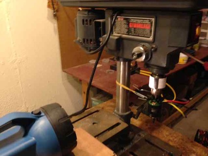 The photo shows a drill press set up to measure its RPM. A white band of paper was placed on the drill press chuck with two vertical black lines marked on the paper 180 degrees apart. To operate correctly, an optical tachometer requires either natural or DC generated light. Standard AC house lighting will not work. The flashlight provides the DC light source for using an optical tachometer when the AC lights are shut off. The optical tachometer readings will vary only slightly as the drill press turns. Use the average or median RPM of the drill press for the Kv calculations. Also in the photo, a brushless outrunner has been chucked into the drill press and held in place using two paper clips and a rubber band attached to its cross mount. Once the drill press RPM is known and the motor chucked into the drill press chuck, it is ready for the AC multimeter readings. Take several readings for each phase and average them. This method is a bit more involved. It requires mounting the motor, ESC and battery to be used on a test stand. A propeller that will load the motor well into its operating range and a means of capturing the no load RPM, or extremely light load RPM, is also required. For brushless motors, the most accurate Kv calculation is obtained with the ESC set to zero (0) degrees neutral timing. Remember that advancing the timing on a brushed motor (using rotation of the brushes) or brushless motor (via an ESC setting) changes the apparent Kv, increases the RPM and Io (no load amp draw). A power meter (aka watt meter) is used to record the volts and amps of the two widely varying loads. A tachometer is used to capture each loadings RPM at the same instant the volt and amp readings are taken. An optical tachometer can be made to work, but a phase tachometer is much easier to use for this purpose. The RPM, volts and amps must be captured at exactly the same instant in time. The Hyperion Emeter II with an RDU (remote data unit) is an excellent tool for this purpose. It is a power meter with a built in phase tachometer and much more. The Emeter II saves up to eight data point "Snapshots". The data saved includes the RPM, volt and amp readings gathered at the same instant. Alternately, the Emeter II with RDU can record or log the data. The logged data can be transferred to a computer and viewed in a spreadsheet format. The data from a Castle Creations ICE or EDGE ESC cannot be used.
All of the data point measurements are taken at FULL THROTTLE! Do NOT use partial throttle readings! Data should be gathered as quickly and accurately as possible. The motor should not be run for any extended period of time, ever! One of the earliest iterations of this method was presented in the December 1989 Ampeer. Collecting the Data High Load Data Point 1
No Load or extremely light load Data Point 2
The math is completed using the previously downloaded Excel workbook spreadsheet titled Rm (the Rm tab).
The results are obtained using differential equations. The results not only include the mathematically calculated Kv but what has been often noted as the Rm, motor resistance. Rm (motor resistance) is a term used to describe the motor resistance of a brushed motor. For a brushed motor it meant only the motor resistance. The term Rd, as used here, means the motor resistance plus the ESC resistance and the resistance of the wire and connectors, so that it may apply equally to brushed and brushless systems. The dynamic resistance, Rd, because it is dynamic, is not a true constant. It varies slightly with the applied voltage and thus the RPM, but it is good enough for our purposes. An example of some actual measured values: (see the spreadsheet Rm for the math)
I2 - current: 1.4 amps
OUTPUTS:
NOTE: The values above are from the same motor as the Kv drill press method which yielded 615 RPM/volt. Calculating the Motor's No Load Current (Io) The Io (no load current) is also a valuable motor constant. The Io is used to compensate for the hysteresis loss and the loss from the high rotational speed caused by circulating electrical currents in the armature laminations and other losses. According to Bob Boucher, "For the purposes of calculating motor performance, one can assume that there is a leakage current or loss current shunting the ideal motor by an amount equal to the measured no load current or Io. The net effective current, and the torque it produces, are decreased to the values: Inet = Iin (current in) - Io (no load current) Torque = Kt x Inet" also from Bob Boucher "Please note: the no load current is measured at some nominal speed usually close to the anticipated running speed." 'Speed/RPM' is governed by the voltage, so that means at approximately at the same input voltage. To calculate the Io, measure the volts and amps using a power meter with no propeller attached to the motor. As Bob Boucher intimated, it is best to use a battery or power supply that applies the approximate anticipated input voltage. Testing at that voltage provides an Io close to the actual running voltage. Some ways to get the suggested lower voltages to use to determine the Io Adjust a power supply to approximately 3.7 volts per anticipated number of LiPo cells and approximately 3.2 volts per anticipated number for "A123" cells for the Io test. Packs to use for testing the Io For LiPo (Li-Polly) packs use the same number of cells as will be used for the onboard system but at storage, or slightly below storage, voltage. To obtain a 'running voltage' for the Io for A123" LiFePO4 batteries is a bit more involved because they do not have a storage voltage. For 4S through 12S packs, a fully charged pack with one less cell than will be used for the onboard system can be used. 2S and 3S packs need to have their voltage discharged or reduced so that the resting voltage is under 3.3 volts per cell. DO NOT ATTEMPT TO CONTROL THE VOLTAGE DUING THE Io CHECK USING AN ESC! A major problem with many suppliers' is that they give an Io without noting the voltage. Io varies somewhat with the volts applied. This causes a problem when the Io is used to estimate the current loss in the power out motor formula. There is also a problem when a supplier gives an Io based on a 'too high' or 'too low' input voltage for the pack being chosen to use in the onboard power system.
Adding one more formula is useful. Power Out Formula
While called constants, the Rm and Io are not truly constant. They vary slightly with the applied voltage. It is important to note that the Rm derived in the following examples is NOT the Rm that is often provided by the suppliers. Cobra C2203/52, wt. 17.5g
Results from spreadsheet:
The maximum amp draw is given as 7 amps. 80% of the maximum is 5.6 amps. On the Innov8tive Designs' prop test table the APC 7x5SF draws 5.6 amps.
The Io is used to calculate the Pout in watts.
Cobra C4130/14, wt. 400g
Results from spreadsheet:
The maximum amp draw is given as 60 amps. 80% of the maximum is 48 amps. 46.04 amps is used for the example as the measured APC 12x8E draws 46.04 amps at 29.6v.
The Io is used to calculate the Pout in watts.
The examples chosen were not arbitrary. They demonstrate some general trends that can be applied to all motors. 'Smaller, lighter' motors have a higher Rm (motor resistance) than 'larger, heavier' motors and therefore a higher voltage drop. In general, for the way that they are used, 'Smaller, lighter' motors have a lower efficiency than 'larger, heavier' motors. One thing that was not demonstrated by the examples is that the highest Kv motor in a series will be the most efficient and have a lower Rm. Why? A higher Kv in the same 'size' motor is created by using larger diameter wire for the windings compared to a lower Kv version of the same series motor with the same type of termination. Not all suppliers provided different Kv motors of the same 'size'. The Cobra C2203/34, which is in the same series of motors as the first example, has a Rm of 0.2255ohms (about 1/2 the resistance of the /52) for a voltage drop of 1.55V at 6.89 amp yielding 5.85Vnet. (Shown in the Examples on the Rm spreadsheet). At 6.89 amps the Vnet is 79% of the Vin and the efficiency is about 72.6%. The /52 is a 52-wind and /34 is a 34-wind. The fewer winds of larger gauge wire on the /34 means that it has a lower resistance and higher Kv than the /52. Another way to derive the Kv is with a phase tachometer and voltage measurement. While an optical tachometer can be used with a brushless outrunner with a paper strip attached to the bell and marked with two black stripes 180 degrees apart, it cannot be used for this measurement with an inner runner brushless, as the motor needs to be 'unloaded'. The Emeter II with the RDU or MDU and the phase tach lead can be used or a device like the AEO Tech KV Meter K0. The motor is run with no load, while the voltage and rpm are recorded. While not the 'true' Kv, it is close enough. For this type of measurement, no load RPM / no load volts = Kv in the units of RPM/volt.
You may be thinking, "What's with all the math?!? You've gone over this a gazillion times already in the Ampeer over the last twenty-five plus years. I don't care about how to calculate motor efficiency, etc. The math just blows my mind. Enough already!" The point is that the generator constant of RPM per volt, annotated as Kv is NOT a rating. It is indeed a 'motor constant'. By itself, the annotated Kv, is not useful in selecting an electric motor for a given application. Shaft RPM, therefore prop RPM equals the Kv times the net voltage.
MORE IMPORTANTLY - Shaft RPM, therefore prop RPM is NOT equal to the Kv times the input voltage at the ESC.
Equally important the K in Kv, a motor constant annotation, has nothing to do with 1000. In kilovolt (kV or kv), kilogram (kg) and kilometer (km), the lowercase k is actually representing the word kilo - 1000 in the Si (International System of Units), which is the modern form of the metric system. More Kv information and the other motor constant information can be found on Skylar's Excellent Motor Constants Page on the Web. Ron van Sommeren does a very nice summation of what Kv is and isn't in an RC Group's post. "A motor's Kv constant says nothing about max.power &, max.current a motor can handle, efficiency, rpm, quality etc.
Link to Ron's post on RC Groups Links to Innov8tive Designs
One final question remains. If none of this information is useful in selecting a motor and propeller, what is? Link to be added in early 2015
|