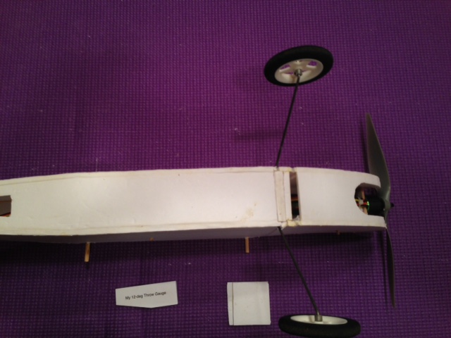
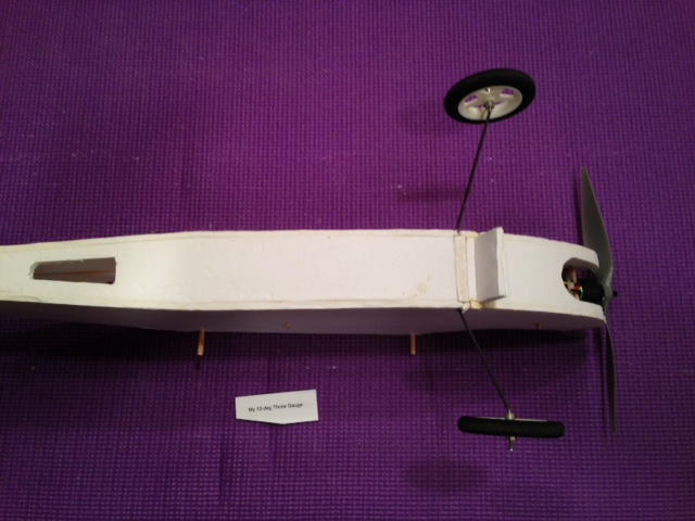
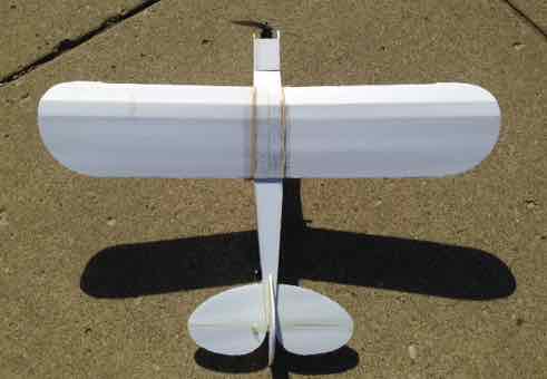
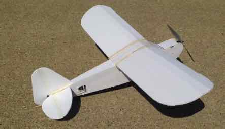
Version 2 Modifications By Ken Myers April 2018 Preface I built two complete fuselages for the Flite Test (FT) Do It Yourself (DIY) Simple Cub. Version 1 (V1) was shared at the EFO meeting on April 11, 2018. I learned a lot from the the first version, but decided that I had not stayed close enough to the 'true' FT concept for the original Simple Cub. In an earlier draft of this article, I imposed too many of MY subjective opinions and physical changes to the FT Simple Cub, without providing any verifiable proof that MY changes were valid. In that draft, it appeared that I was knocking Flite Test and the Simple Cub design. That was absolutely not MY intention. I like the concept and goals behind Flite Test very much. In their videos, the people behind Flite Test seem to be some of the nicest, most caring and sharing people that I've come across in years. In April 2018, I did a presentation at the Midwest RC Society. The presentation was called "Who and What is Flite Test?" The highlights of the presentation are here. The article describes who and what Flite Test is and what they aspire to be. In April 2016 I built a version of the FT Old Fogey, but it was not exactly the true FT Old Fogey. I increased the size by a factor of 1.22 times. I ran into several problems, but they were not related to MY size change. "FlightTest.com & The Old Fogey" was the first of two articles that I published about the Old Fogey. The first article shared some issues that I found with the plane's design. The second article was "More on the Old Fogey's Old Fogies (Includes Power System Comparisons/EMAX & Cobra motors - EMAX ESC & CC Thunderbird)". It discussed the specific modifications for MY Mk II version and the differences in the system efficiency of the two power systems I had purchased for use in this plane. In April 2018 I decided to give one of their designs another try, the FT Simple Cub. I had used portions of the Flite Test Simple Cub videos, and a printed sheet of their plans for the Simple Cub, in MY presentation to Midwest. FT recommends a 3S 1000mAh LiPo battery for the Simple Cub. I have six of the recommended 3S 1000mAh LiPo battery packs from when I wrote the series of articles called "Learning About LiPo Batteries". The articles started in the March 2016 Ampeer. I had also used 3S 1000mAh packs in MY enlarged version of the Old Fogey. MY goal was to attempt to build the FT Simple Cub as close as possible to the FT design. I must admit that doing that is extremely difficult to do for me. While preparing MY presentation for Midwest, I watched various portions of the Simple Cub Build video. During these viewings I realized that several different versions of the Simple Cub were built and then edited together into the single build video for the Simple Cub. I used the whole video, played in segments, to guide me through MY first DIY build (V1). The build video starts with the construction of the basic 3-channel version, but it meanders back and forth between that build and the build of the 4-Channel version with the larger Power Pack C motor. The 'switching back and forth' between different builds was, at times, confusing. I am over analytical. With 60+ years of building and flying model airplanes, I tend to superimpose MY personal views and opinions onto their original design. That is really not fair to the original designer. I tried very hard to not make any changes to the Simple Cub, but some were inevitable. Using a hot melt glue gun and hot melt glue is an integral part of Flite Test's build concept for their laser cut kits. In 2016, I built MY enlarged, DIY prototype Old Fogey using Foam-Tac, because I had it on hand. I had tried to use MY wife's craft type hot melt glue gun. It didn't work well for the purpose of building a large FT design in MY 57 degree F basement. I ordered the Adtech Pro200 Glue Gun (200 Watt) glue gun and glue sticks from Flite Test. I built the prototype for MY new trainer design, the RUA 2-4-10, using the Adtech Pro200. I built the second prototype of the RUA 2-4-10 using Titebond Original Wood Glue. Each completed airframe was weighed before any equipment was installed. The second prototype, using Titebond, turned out a bit lighter. I used Titebond on both the V1 and V2 versions of MY DIY Simple Cub build. MY Simple Cub is built as the 3-channel basic Simple Cub for possible use as a training plane for new student pilots. I believe that using their hot melt glue gun method makes assembling their FT laser cut kits fast, and the weight gain only slight, when compared to Titebond. With some preplanning, regarding the cutting of the parts from the DTFB and the assembly of the DIY version, I found that I could work continuously, using Titebond glue, and not have to wait for the Titebond to dry. I also used epoxy to attach the 3/32" thick, plywood firewall to the Swappable Power Pod and the servos of MY version 2 of the DIY Simple Cub. I mostly fly at the Midwest RC Society 7 Mile Road flying field. The runway is reasonably short-cropped grass. In a Simple Cub video, that I shared at the Midwest April 2018 meeting, I noticed that two Simple Cubs 'flipped' on landing. View about 20 seconds of the video I showed to Midwest. The grass runway in the video seemed to be very similar to the Midwest flying field. At the end of the build video, Josh Flies the 3-channel version. He misses his first attempt at landing on the cement pad that he is flying from and lands short. There is a quick blip of a video que and then... Watch about 10 seconds The Simple Cub is certainly not supposed to be scale-like, but it shares several design elements with other Cub model designs. Over the years, many of MY student pilots have chosen various Cubs to learn on. All of them have had the axles of the landing gear aligned with, or just behind, the leading edge of the wing. Once MY students started landing their Cubs, they always flipped over. It takes a lot of finesse to land a Cub-like plane, with the axles aligned with the leading edge of the wing, without flipping it. Low time pilots lack the finesse to do it consistently and the flip can sometimes put an end to flying for the day if the vertical stabilizer is damaged too much. On several of MY students' 'Cubs', when possible, we physically moved the landing gear forward a bit. That helped. They were not as concerned about flipping the plane on landing. In version 2 of MY DIY Simple Cub I made a provision in the Fuselage Doubler to move the landing gear forward, if I found it necessary. The fuselage doubler retains the original position and I added another slot 5/8" forward of the original position. I also eliminated the rear position for the float attachment, as this trainer will not be used with floats. 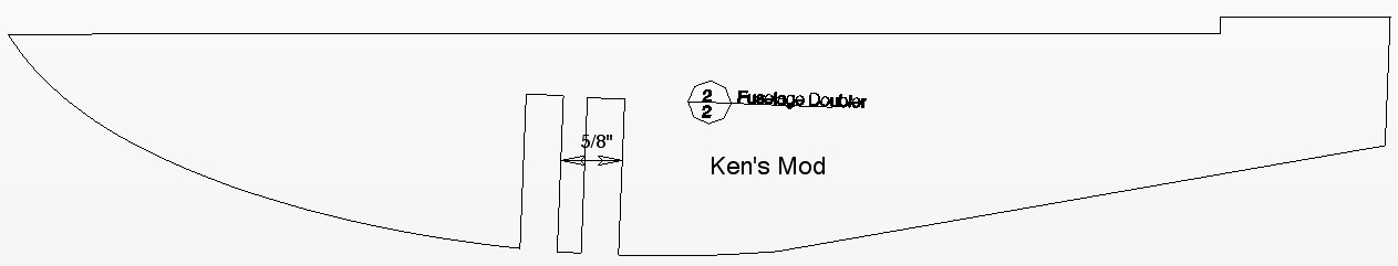
This is not the final version. The front slot was moved further forward. To maintain strength in the landing gear area, I made a second landing gear tab to fill the empty slot when not in use.
The extra tab is fully inserted for flying. The landing gear position can be switched, if I find it necessary for MY students, since the landing gear is only pressure fitted into the fuselage.
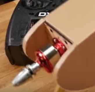
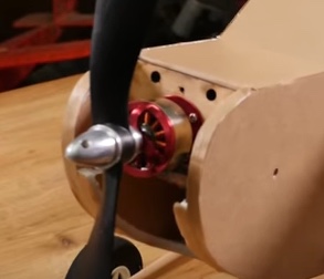
The Swappable Power Pod is a MAJOR concept in the FT Swappable designs. Back in the 'olden' days of RC we had 'swappable' onboard radio system components boxes built into our models. The expensive onboard radio systems were attached to the box. The box containing the radio equipment could then be swapped between models. Later manufacturers built 'bricks' that included the electronics for the receiver and, usually, the electronics for 3 servos. The 'bricks' could be moved from plane to plane. Flite Test decided to 'run' with this idea and make the 'expensive' power system components swappable with a Swappable Power Pod. They created a whole series of airframes around this concept. Watch about 10 seconds of the video. MY version 2 uses the FT Swappable Power Pod as designed by Flite Test. The answer to that question applies whether a top hatch is desired to 'load the battery or not. What top hatch? There is no top hatch on the FT Simple Cub! The why and how of adding a top hatch is in the next section, but using a top hatch appears to be Josh Bixler's original intent as stated in the build video. Watch about 10 seconds where he notes the battery sliding in from the top. The Simple Cub build video shows that the bottom of the firewall is NOT aligned with the bottom of the Power Pod. Watch about 5 seconds of this Power Pod build for the Simple Cub How far the firewall extends below the bottom of the Power Pod determines the angle for the motor down thrust. The plywood firewall included in the Simple Cub laser cut kit measures the same as on the DIY Plans; 2" wide and 1-11/16" high. The Simple Cub has no decalage, or difference in the datum line angle between the wing and horizontal stabilizer. Both the wing and horizontal stabilizer are horizontal to the datum line. Any line parallel to the top of the fuselage is parallel to the datum line. 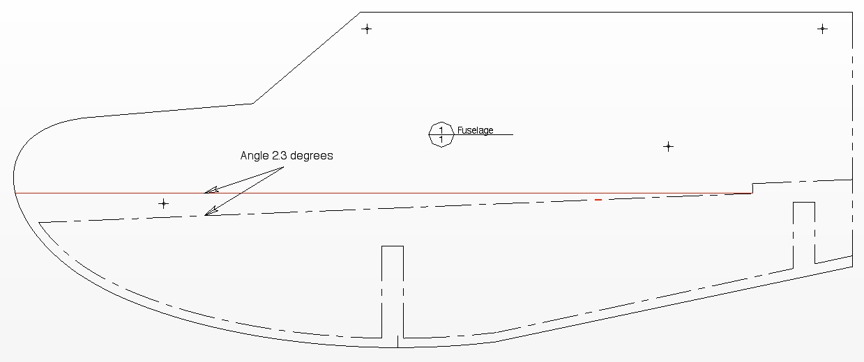 The top of the Fuselage Doubler runs at an angle of -2.3 degrees to a parallel datum line. 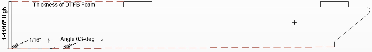 Josh notes in the build video that the top of the firewall should extend about a foam thickness above the front of the Swappable Power Pod. When the Power Pod slides into the fuselage on the top of the doublers, which are acting as rails, the firewall is holding the front end of the Power Pod up by 1/16" above the rails at the front of the Power Pod. 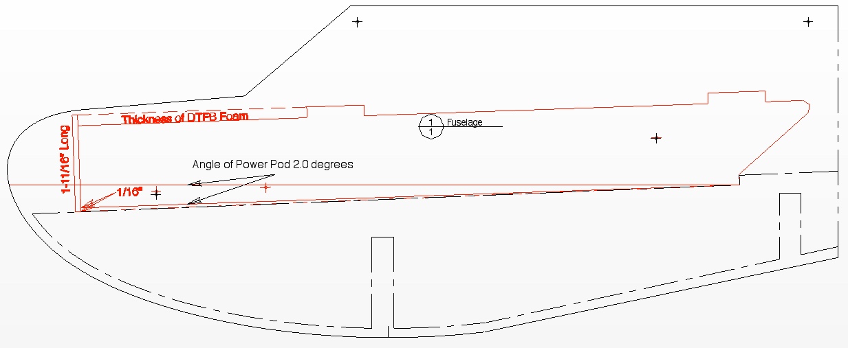 The motor down thrust is then -2 degrees to the datum line. How far should the firewall extend below the bottom of the Power Pod? 1/16". As previously noted, during the Simple Cub build video, Josh notes that the ESC will be placed on the bottom of the Power Pod and the battery will slide in on top of the Swappable Power Pod through a top hatch. 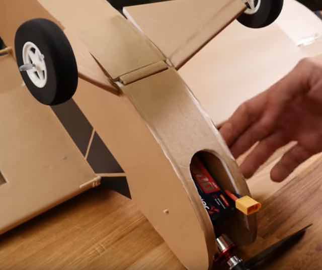
https://youtu.be/Uw0_9Zmcewc?t=4907 As shown in the screen capture above, that was not how it was done on the completed design. The ESC ended up on the top of the Power Pod floor and the battery on the bottom. The firewall on the FT design is in front of the top front piece of the fuselage and does not reach the top of the fuselages sides.
I PREFER a top hatch. I just don't like turning a plane over to 'load' the power battery. I created a top hatch using the front part of the Fuselage top and modifying the the front of the Fuselage. 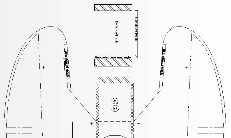
Fuselage Mods & New Top Hatch Note that in the diagram, the inside of the plane is shown. It looks like the hook 'n loop slot, under the hatch, is on the left side, but it is on the right side. The new hatch is hinged on the left side of the Fuselage with strapping tape, which is also known as Fiberglass Filament Tape. The hatch closure is two pieces of hook 'n loop fastener. One piece of hook 'n loop is placed in a slot in the right Fuselage side and the other piece is on the hatch over the piece in the slot on the right side of the Fuselage. A Quick Note: Strapping tape was also used across the flat side of the hinge line of the elevator and rudder. 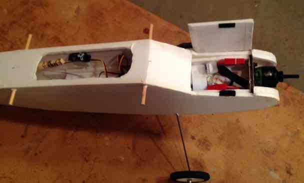
This is a photo of MY V1 version showing the hatch open. The V1 version had a 3/16" plywood firewall with 4-40 bolts and blind nuts holding on the motor. To keep MY model more in line with the original design, MY V2 version has a 3/32" firewall with the motor attached with screws. FT does not provide motor screws in their laser cut kits. Screws, to hold the motor to the firewall, are not available in their store. The size and type of screws is not noted on their DIY plans. The photo showing the servos, pushrods and receiver is from MY V1 version. They were installed in a different position in MY V2 version. The explanation for the parts movement is explained later. 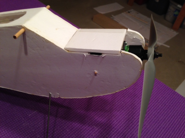 I did change the height on MY firewall so that it fits 'just' under the hatch. The width of a LiPo that will fit on top of the Power Pod floor and between the hook 'n loop strap is only about 1-3/8". The FT Simple Cub video, shown at the Midwest meeting, also demonstrated an issue with battery security. View a little over 30 seconds of the video to where it crashes. A version of the Simple Cub, shown in the video, was 'hit' mid-air by another aircraft. The impact dislodged the battery. It is not good if a battery can come out at any time, for any reason. The battery needs to be secured with a strap as well as a strip of hook 'n loop fastener. I made slots for a hook 'n loop strap in the Swappable Power Pod and installed a strap. The FT DIY plans don't show a hole, or holes, on the bottom of the Swappable Power Pod to access the leads from the electronic speed control (ESC). That really isn't a big deal, as the Power Pod floor is DTFB and it is easy to cut a hole through it where desired. 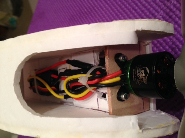 For MY version, the electronic speed control (ESC) is mounted on the bottom of the DTFB Power Pod and the battery on the top of the Power Pod. The battery area is accessible through the hatch I added. Flite Test keeps the power selection simple by recommending an inexpensive motor/battery/ESC/prop combination. The recommendation makes it easy for a beginner to select the required power system. The Power Pack B (Fixed Wing Small) is recommended for the Simple Cub. The motor in Power Pack B is the Emax MT2213-920KV 53g 935Kv outrunner. The recommended ESC is a BL-Heli 20 amp (with XT60 connector). The Power Pack contains two propellers of the slow fly type; a 9x4.5 and 10x4.5. The recommended battery for the Simple Cub is the Lumenier 1000mAh 3s 35c Lipo Battery. The recommended propeller for the Simple Cub is the HQ Prop 8x4.5 CCW Propeller Slow Flyer, which is not included in Power Pack B.
At the beginning of the build video, Josh Bixler states, "Now in this video we are going to be showing you how to build the basic 3-channel."
That makes the power system selection extremely easy. Or does it? Watch for 20 seconds. In the build video, Josh said, "The motor we are going to be puttin' on is the 2215/09 and that's our C Pack. That's for our Warbirds and bigger aircraft and our ah more experienced fliers. If you are flying something smaller, that takes a full-size swappable, you're probably going to be referred to a B Pack. In all of our airplanes, that we design, we refer to the best power pack that we recommend on every single one. So there won't be any confusion." Power Pack C (Fixed Wing Large)
There is a difference in the motor weights in the two Power Packs. The difference in weight affects the battery placement to obtain the recommended initial center of gravity (CG) of 1-3/4" from the leading edge of the wing. This does seem a bit confusing, especially for a beginner in the hobby. I chose to use a Cobra C2213/26. It had the closest specifications to the motor in Power Pack B. The Cobra motor weighs 61g with a stated Kv of 950. The Cobra is more expensive than the Emax, but Cobra motors are MY motor of choice. There is only an 8g difference in weight, so the effect on the CG is minimal. I also chose a Cobra 22A ESC with 2A Linear BEC. The switching BEC Cobra 33A ESC was used on the final version. Especially for the 4-channel version, the Cobra 33A ESC with 3A Switching BEC would be a better choice. It has a switching BEC and can safely handle more servos than a linear BEC. MY power system selection, including the 3S 1000mAh LiPo battery, IS equivalent to what is recommended by Flite Test. FT recommends that the initial safe center of gravity is 1-3/4" behind the leading edge of the wing. The video shows how to check the center of gravity. Watch about 20 seconds of the video. Once MY V1 version of the plane was completed, I placed a GensAce 3S 1000mAh in the battery compartment as far forward as possible. This battery placement was close to what was shown in the build video. With the battery at that point, MY plane was extremely nose heavy. SPONZ (Dan Sponholz), the person who creates the DIY plans for FT, had also reported nose heaviness in the Flite Test Forum thread about the Simple Cub. "With the 2200 shoved as far back as it could go, the plane was a little extra nose heavy, ..."
 I moved the battery as far to the rear of the hatch opening as I could to still be able to get it in and out of the hatch. It was still much more nose heavy than shown in the build video. Tail weight was added to achieve the recommended CG location. I have no idea why MY V1 version ended up so nose heavy when using 1-3/4" from the leading edge as the balance point for the CG, but MY version 2 did as well. While watching the pushrod installation on the build video for the Simple Cub, I noticed the relatively long run of extremely small diameter wire used for the pushrods. The pushrod wire has a diameter of approximately 0.0395". I also noticed how flexible it was. Watch about 15 second of the video and note how easily the pushrod bends. I wondered if this was going to be a problem. I searched the Flite Test Forum and Store for comments about the pushrods. 1. Shakeyjake, "After I crashed MY Simple Cub several times I finally figured out that the rudder and elevator control rods were flexing so bad that in the right conditions the rudder would go slightly left even when I was full rudder right..."
2. Brett_N , "I second the better control rods. I'm only using the small gauge on the mini's and even then I zip tie them. They're OK for aeilerons on the bigger planes, but no good for anything requiring more than about 6 inches of length."
3. NATHANAEL 13th Aug 2017, "They bend
For the unflown V1 version of MY DIY Simple Cub, I chose to use a very, very old pushrod method. That method yielded a much less flexible pushrod. Watch about 1 minute & 20 seconds of this video I installed the servos in MY V1 version using the method described in the build video. I used the Flite Test recommended hot melt glue gun and hot melt glue that I had purchased directly from Flite Test. While MY Simple Cub V1 was being passed around at the April 2018 EFO meeting, the rudder servo fell off the side of the fuselage. Before doing the servo installation, I had MY suspicions about the integrity of this type of installation, but I thought I just had to give it a try to be fair to Flite Test. I searched the Flite Test Forum and found a comment regarding a servo letting go during the maiden flight of a Simple Cub. SPONZ, "About a minute or two into the flight, the elevator servo let loose inside the fuselage and I had no pitch control. Down she went."
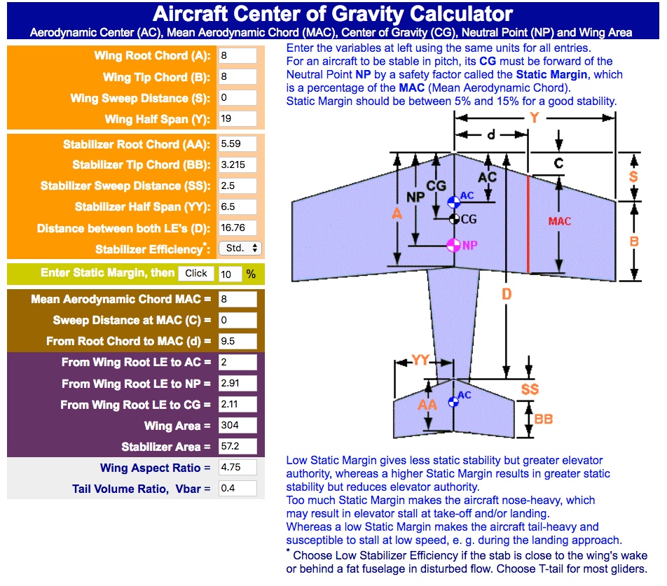
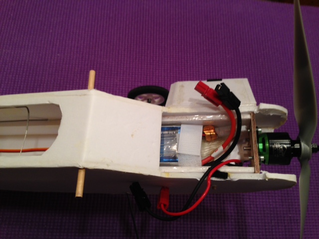
There is a little irony in who it happened to. SPONZ is Dan Sponholz, the guy that creates the beautiful plans for Flite Test. This modification is in conflict with the simplicity that FT was attempting to achieve with their servo and pushrod installation. I apologize, but I just had to do it. I moved the servos to the outside of the rear of the fuselage by cutting holes for them in the fuselage sides towards the rear of the plane. 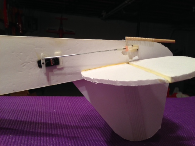 Regular size, commercial pushrods were used. A Z-bend was used to connect the proper length pushrod to the servo arm and a nylon clevis connects the pushrod to the control horn on the moveable surface of the rudder and elevator. 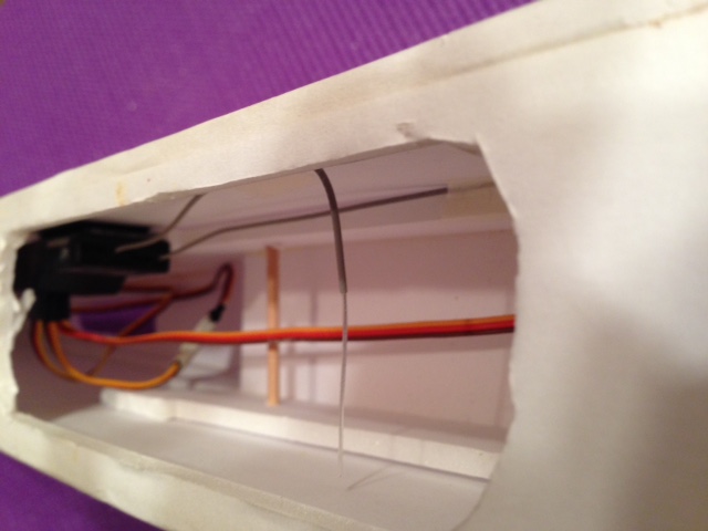 Originally, Hitec HS-53 servos were used. They weigh approximately 9g each. Their 10" servo leads were long enough to reach the repositioned receiver position in the V2 version. A 3" servo extension can be seen in the photo, but it was not necessary. After the maiden flight, the servos were changed to Hitec HS-82 servos to add more weight to the tail of the aircraft to achieve a CG of 2" from the leading edge of the wing. The HS-82s weigh approximately 19g each. The HS-82s required no servo extensions. The FT Pushrods could be used using the FT Linkage Stoppers instead of a Z-bend for attachment to the servo arm. The elevator pushrod is only 4-1/4" long and the rudder only 5-1/2" long, therefore flexing of the pushrods would be minimal. On the Flite Test Store page for the FT Simple Cub kit and on the downloadable DIY plans, the recommended throw, on ALL of the movable control surfaces, is 12o. There is a throw gauge provided on the DIY plans and the laser cut kit for this plane. Watch about 10 seconds of the video The part of the build video, linked above, shows Josh using the Throw Gauge. The problem is that both of the angles on the Throw Gauge are too steep to provide a gauge for setting the deflection angle to 12o. 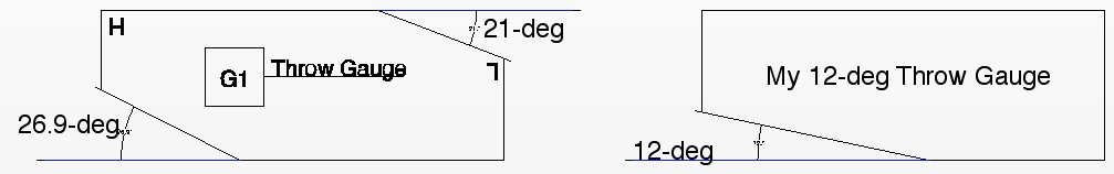 For MY Simple Cub I made a 12o DTFB throw gauge to check the control throws on my version. The plywood control horns, drawn on the DIY plans and provided in the laser cut kit, are too short to provide only 12o of throw when using the inner most servo arm hole and outer most control horn hole. To achieve the recommended 12o a computer style radio must be used so that the throws can be limited in the transmitter or dual rates set up on the transmitter. For MY version, I chose to use the commercially available Great Planes Nylon Control Horns Large, which are no longer available. Dubro Control Horns Nylon Large can be substituted, but they do not have the nice Phillips head screws that were included in the GP horns. The pushrod is placed in the inner most hole of the servo arm and clevis in the outer most hole of the GP control horn, the throw is just a tad over the recommended 12o on the moveable surfaces. The maiden flight demonstrated that 12o of throw is plenty when this plane is being used as a trainer. April 26, 2018 On the morning of April 26, according to Windfinder.com, the predicted winds were to be 7 mph from the west. At about 10 a.m., the winds were out of the west at 5 mph to 10 mph at the park on 5 Mile Road near Plymouth, MI. Before taking to the air for the maiden flight, I completed two short hops to check the trim. Both hops showed the need for right trim. Right trim was added to the rudder for the maiden flight. Only one flight was made that day, as there was a firewall issue upon landing after the maiden flight. Even though the firewall was attached to the Power Pod using the FT method of glue and packing tape, the firewall broke off the Power Pod when the plane, more or less, ended up landing on its nose after a very short roll out. I was not too surprised when it ended up on its nose. During both test hops, the plane landed on its wheels and then immediately nosed over. The grass surface of the soccer field should have been just fine and I don't believe it played a part in the nose overs. I could see that the power off decent angle was just too steep. The maiden flight lasted for 4 minutes and 4 seconds. The 3-channel Simple Cub flew very nicely. I checked the resting cell voltages of the Dinogy 3S 1000mAh 65C LiPo Pack. According to my Fluke multimeter, each cell was at 3.989V. I placed the pack on a commercial discharger that I use to take them to my selected storage voltage of 3.77V per cell. While reattaching the firewall to the Power Pod, I referenced the notes that I'd taken at the flying field for other changes that I wanted to make. 1/2" wide by 1-3/16" high doublers were cut from DTFB and attached inside the front of the Power Pod where the firewall attaches. The doublers provide more gluing surface for the firewall. The firewall was epoxied to the Power Pod and new doublers with 1/16" of the bottom of the firewall extending below the Power Pod. Strapping tape, NOT packing tape, was used to reinforce the firewall attachment to the Power Pod. The motor was attached to the firewall with a washer under each left leg of the motor mount, when viewed from the rear to provide a bit of right thrust. While epoxying the firewall back onto the Power Pod, I noticed that it was pushed in in the middle. That confirmed my suspicion that the firewall is too thin. While setting the wing aside, I noticed that the wing trailing edges along the center, where the rubber bands go across the wing, needs protection. I added some 1/16" plywood cross strips there. 1/32" would work, but I'm trying to get more weight further back for better balance. Craft sticks could also be used. While reinstalling the Power Pod, I noticed that the landing gear was wobbling back and forth. Inspection showed that the wire gear had enlarged its slot in the Landing Gear Tab. I forced epoxy down the gear legs in the Landing Gear Tab using a toothpick. I also noticed that the landing gear, being forced rearward after the three not so great landings, was enlarging the gear slots in the sides of the fuselage. I didn't do anything to fix that at this time. From my maiden flight, and the video segments that I had previously pointed out, it appeared to ME that the initial safe center of gravity was too far forward. I calculated the CG using an online CG Calculator. I used the measurements from the DIY plans to gather the data for input into the calculator. I used static margins of 5%, 10% and 15%. For an aircraft to be stable in pitch, its CG must be forward of the Neutral Point NP by a safety factor called the Static Margin, which is a percentage of the MAC (Mean Aerodynamic Chord). Static Margin should be between 5% and 15% for a good stability. Low Static Margin gives less static stability but greater elevator authority, whereas a higher Static Margin results in greater static stability but reduces elevator authority. Too much Static Margin makes the aircraft nose-heavy, which may result in elevator stall at take-off and/or landing. Whereas a low Static Margin makes the aircraft tail-heavy and susceptible to stall at low speed, e. g. during the landing approach. * Choose Low Stabilizer Efficiency if the stab is close to the wing's wake or behind a fat fuselage in disturbed flow. Choose T-tail for most gliders. 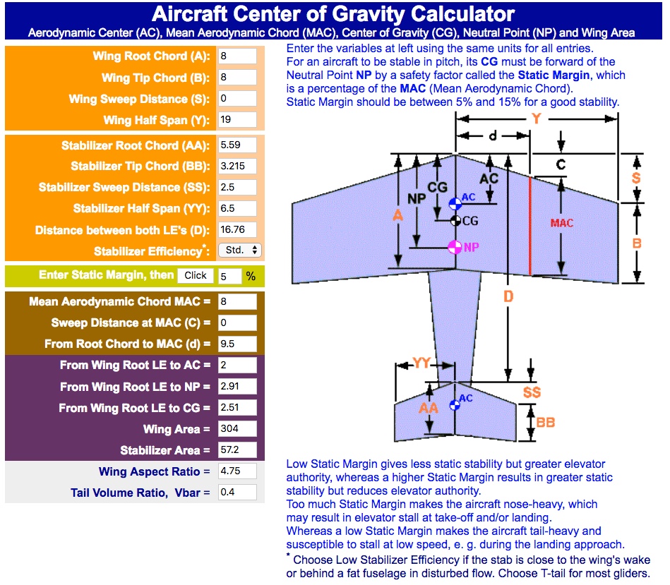
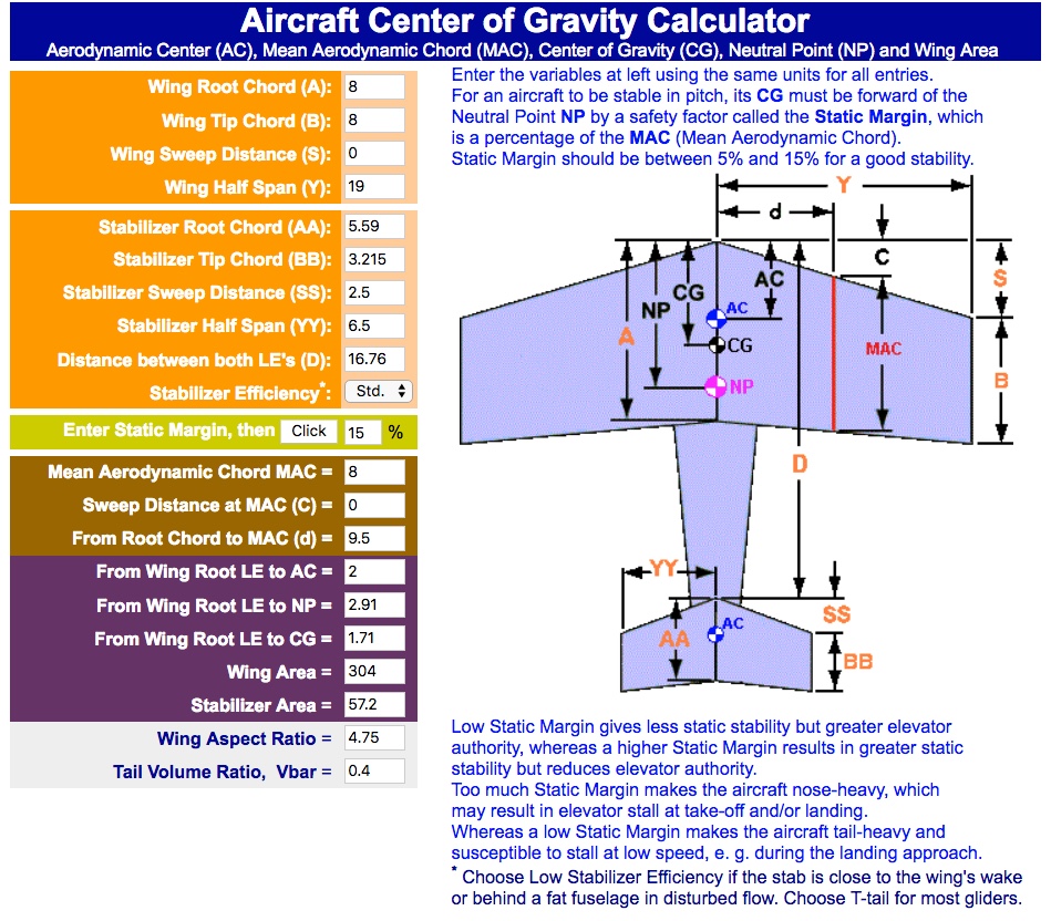
Static Margin of 5%, about 2.5" from the wing's leading edge - heading towards tail heavy
The fore and aft balance line is commonly noted as the CG. To learn more about this topic, there is an article titled "Fore and Aft Balance: Initial Safe Center of Gravity (ISCG)". CG is used here to keep terminology consistant. I marked the wing for the CG to be 2" behind the leading edge of the wing. As previously mentioned, I replaced the Hitec HS-53 rudder and elevator servos with Hitec HS-82 servos.
That worked out perfectly. The CG is at 2" with a GensAce 3S 1000mAh LiPo battery installed. The current weights are reflected in the Finished Specifications. On April 23, 2018, Mike Russell brought over his new laser cut kit for the Simple Cub. I was able to get some accurate measurements for some of the kit contents that are not readily available with the DIY information. I was also able to get a few questions about the kit answered. The really big question I had was, "What is the actual size of the 3/32" plywood firewall. On the DIY plans it measured 2" by 1-11/16". Several references on flitetest.com noted the firewall for the Swappable Power Pod as 2" by 1-3/4". The kit firewall measured just under 2" wide by 1-11/16" high. Other Useful Measurements of Kit Components Skewer diameter: 0.115" - That is between 7/64" and 1/8" and close to 15/128" which is 0.117". Landing gear diameter: 0.095" - That is close to 3/32" which is 0.09375". 2.5mm is 0.0984252" and 2.4mm is 0.0945". Pushrod diameter: 0.0395" I thought maybe I measured incorrectly but 1mm is 0.0393701", so I believe that it is 1mm diameter wire. A few questions answered: Do motor screws come with the kit? No.
There is no landing gear wire mentioned in FT Simple Cub Parts List on store site. Is it there? Yes. Type: Trainer/Sport
 Plan Form Wing Area: 293 sq.in. FT said 302 sq.in.
 Watts in using APC 10x5E: 139.6
I found the following regarding weights for this plane interesting: "580 grams without the battery ,running a 2212 1400kv on a 8x6 prop"
"Mine is 570g without battery"
Motor: Cobra C-2213/26
Transmitter:Tactic TTX650
Note: Rudder is mixed 100% to Ailerons to allow for use of the left hand for steering on the ground and right hand for in the air. K&S Music Wire 3/32"x36" was used for the landing gear, which is about the same diameter as the wire supplied by FT for the landing gear wire. Unfortunately, Horizon Hobby/Tower Hobbies no longer carries the K&S wire. It might be able to be found in a local hobby shop. Dubro Micro Sport Wheels 2.50" were used and attached to the axles with Dubro Dura-Collars 3/32". 3/16" diameter wooden dowel rod was used for the wing hold downs and tail skid and 1/8" diameter wooden dowel rod was used for the dowel to hold in the Swappable Power Pod. Addendum A second wing with ailerons was built. The wing servos are Hitec HS-53s. They use a commercial standard size pushrod connected to Great Planes Nylon Control Horns Large. The following were the changes required to change the 3-channel FT Simple Cub to a 4-channel:
Plan Form Wing Area: 293 sq.in. FT said 302 sq.in.
Watts in per pound APC 10x5E prop: 108 Watts in/lb.
Transmitter:Tactic TTX650
Note: When the wing was attached to the fuselage, both ailerons moved up in relationship to the area on the wing near the center section. I readjusted them to the area on the wing near the center section and now they look down when they are off the plane.
|