logo Flying High With Electric Power!

The Ampeer ON-LINE!
February 2018
The Club Newsletter of the Electric Flyers Only, Inc
AMA Charter 2354
Walled Lake, MI, USA

Editor: Ken Myers

Fly the Future - Fly Electric!

What's On This Site:
Site Table of Contents

President:Vice-President:Secretary-Treasurer:
Ken MyersRichard UtkanRick Sawicki
1911 Bradshaw Ct.240 Cabinet5089 Ledgewood Ct. W.
Commerce Twp., MI 48390Milford, MI 48381Commerce Twp., MI 48382
(248) 669-8124(248) 685-1705(2480 685-7056
Board of Directors:Board of Directors:Ampeer Editor
David StacerArthur DeaneKen Myers
16575 Brooklane Blvd.21690 Bedford Dr.1911 Bradshaw Ct.
Northville, MI 48168Northville, MI 48167Commerce Twp., MI 48390
(248) 924-2324(248) 348-2058(248) 669-8124
The Next Meeting: Date: Wednesday, Feb. 14 Time: 7:30 p.m.
Place: Ken Myers' house

What's In This Issue?

Moving to LiFePO4 Al Straub asks questions about A123 cells and Ken answers them. Making A123 Packs Claude Vest asks how to assemble them, Ken replies with a link to a video that will help.
More On Soldering Tools John Zook shares where he purchases soldering tools. Soldering for RCers Gary Gullikson wrote this article especially for Ampeer readers.
Up Coming Hamburg Flyers R/C Club Swap Meet Feb. 3 swap meet announcement Hitec X1 PRO PROFESSIONAL BALANCE CHARGER/DISCHARGER and Hitec POWERBOX 17A SWITCHING DC POWER SUPPLY Ken reviews this excellent value charger.
Upcoming E-vents
Send Ken email

Moving to LiFePO4
From Al Straub via email

Ken,

     I am looking into transitioning from LiPos to LiFe batteries (A123's) and wondered if you could tell me what a typical internal resistance (Ohms) would be for an A123 cell? The answer is probably somewhere in the EFO newsletters you have posted but could you please tell me which one, or what the value should be for a 1100MAH Cell?

     I have done some tests on a 2Sx1000 LiFe ("Ultralast" brand) pack from Batteries + Bulbs. The IR number I get per cell is ~100 milliohms but that sounds a little high to me. Seems like it should be more like 10-20 milliohm. I expect that the Batt+ cells are not intended for high current operation (powering an RC motor).

     I have some A123 cells on order so should be able to answer my question myself (I hope!) once they arrive.

Thanks again,
Al Straub

My reply

Hi Al,

     The internal resistance of LiFePO4 cells only tells part of the story.

     There is a very strange aspect regarding their IR values. The measured IR, at 'room' temperature, is higher when near 'full' voltage, and then again when measured near 'empty' voltage. It actually drops when tested in the 'middle' voltages.

     I just measured a known good pack this morning at about 22-deg C. It was nearly 'full' and had been setting since last weekend by my plasma TV.

     The pack, at about 3.55V per cell, is a 4S 1100mAh A123. It averaged 47mOhm with a range of 46mOhm to 49mOhm.

     The same pack, at about the same temperature, at about 3.42V per cell, averaged 40mOhm with a range of 39mOhm to 42mOhm.

     The 1100mAh A123 can easily handle 12 amps to 14 amps continuous and up to 17 amps or 18 amps burst.

Later,
Ken

Return to "What's In This Issue"

Making A123 Packs
From Claude Vest via email

     Once again I want to thank you for keeping me on your emailing list for the newsletters.

     On the subject of A123 batteries, do you have a link to an article on how to build your own packs, charging, etc.

     I've been flying glow fuel for the past few years, but want to return to electrics.

Tight Turns,
Claude
AKA Simitar Knut on YouTube

Hi Claude,

     I learned how to build A123 packs from a site long gone from the Internet.

     It really wasn't hard for me because I'd already been building NiCad and NiMH packs. The big difference is wiring the balance connector for the A123s.

     The trick really comes from remembering to wire from the most negative to most positive in the series.

     I did find a YouTube video that demonstrates the process.

     It is definitely not the best video, but gives the general idea.

     For the balance connectors, I don't run the wires from the cells like he shows them in the video. I just use the balance connectors I purchase from maxamps.com.

     They are JST-XH connectors. You will find them for 2S through 6S. They are way down the page if you are scrolling. If you know how to search a Web page just type JST-XH xS, where x is the number of cells.

     I also do not use wire to join the cells. I use braid that I picked up somewhere in my NiCad/NiMH days.

     Dave Thacker, Radical RC, still carries soldering tabs and bars.

     Charging is pretty straight forward. Select LiFe on one of today's chargers and it will set the charge termination voltage to 3.6V per cell.

     I charge the 1100mAh versions at 1.1 amps at home and 2.2 amps when at the flying field.

     I charge the 2500mAh versions at 10 amps all the time.

     Both versions are left fully charged all year round.

     My 2300mAh/2500mAh packs live in their respective airframes all year round.

     I have a couple of the 1100mAh packs that I use in a trainer. I rotate them, charge them and fly them at the field with my student pilots.

     Having a good soldering iron and skills is essential. Until I got my HAKKO 888D, noted in the December 2017 Ampeer, I used a hammer head soldering tip, still available at Radical RC, to solder the braid to the cells.

     The article is, "Confessions of a Soldering Hack".

     Now I use the biggest, flat HAKKO tip I could get, and a fairly high heat setting, to solder the braids/tabs. I solder the balance leads onto the braids/tabs between cells and the most negative and most positive balance connector lead to the negative and positive power leads respectively and cover them with shrink tube before soldering the leads to the appropriate cells.

     I don't use heat shrink on my packs. I wrap them in strapping tape that I purchase at Staples. It is actually called Staples Fiberglass Filament Tape, 0.9" x 60 Yards.

     It is really important to remember that A123 cells are not for everyone and especially not for every plane.

     The packs work best in sport and sport scale planes, which also includes many trainers.

     Hope this helps to get you started.

Sincerely,
Ken

Return to "What's In This Issue"

More On Soldering Tools
From John Zook via email

     "Ken, if you need to locate tips and other soldering equipment take a look at MCM electronics; MCM Electronics: Home and Pro Audio/Video, Security and Test Equipment.

     They have a large selection of soldering gear and related accessories.

     I use one of the MCM soldering stations and it works very well without being too costly.

     I replied to John and asked, "Got snow? ;-) WeÕve got about a foot on the ground down here."

     He replied:

     Yup. At least a footÊ up here. (He lives in northern Michigan KM) Just got back from indoor flying in Charlevoix, MI.

John Zook

Return to "What's In This Issue"

Soldering for RCers
From Gary Gullikson via email

     I didn't have anything else to do so I whipped up the attached article. You are welcome to edit, reformat, shorten or simply not use it. I won't be hurt.

     Keep up the good work on the newsletter.

     By the way, I am getting ready to build Pat Tritle's new DC-3 kitted by Dare/Brodak.

     The model has a 60" wingspan and will be built without retracts and kept light to be a floater. It will be finished in Ligh-tex "bright silver" iron-on covering from Airborne Hobbies, and with American Airlines Flagship Detroit livery and little people profiles in the side windows as furnished by Callie Graphics.

     I am not a fan of LED lights on models but may make an exception with landing lights on a switch plus navigation and strobe lights.

     I am going "all out" with new Cobra motors and speed controls and six new servos, nothing out of my used stuff stash.

     I have a number of other stalled projects but will leapfrog over them to build and fly the DC-3. May play a CD of a DC-3 droning on my boom box when flying the model.

Gary Gullikson, Garden Grove, CA Ê
E-Challenged on RC Groups

* * * * *

Background

     I was a leadman in old school electronic assembly back in the early 60's. I became a soldering instructor in the personnel training department and enjoyed it. I had to train people, with no experience, to do soldering to military standards as well as component identification and basic assembly techniques, in a one week training course which concluded in a certification test with various types of soldered connections.

     I am mostly an RC electric powered scale modeler and spend too much time reading posts in RC Groups forums. It seems to me that there is a lot of well meaning, but incomplete, advice to those having difficulty in soldering or new to soldering. The following is my attempt to provide concise and practical how-to information on the subject.

Tools, Materials and Accessories For Occasional Soldering Jobs

Soldering Irons

     A soldering iron (Weller, etc) with available and replaceable tips in the 37-47 watt range is fine for soldering of wires to connectors. The tip should be of the "chisel" or flat type for most connector soldering and the pointed type is best for soldering wires to printed circuits. There are advantages to heat adjustable "soldering stations" but they are somewhat over-kill for the occasional solder.

     For soldering steel wire landing gear assemblies, a 75-100 watt iron with a large chisel tip is appropriate. Use of a torch and different techniques for 1/4-scale wire landing is outside of the scope of this article.

Soldering Iron Holder and Accessories

     A simple holder with a sponge for frequent wiping of iron tips is essential to safely keep the iron out of your lap when not in use.

     There are various devices that act as a third hand while you hold the iron in one hand and the solder in the other. You can make a similar device with alligator clips or clothes pins to hold wire in position.

     A small bench vise is handy to hold connectors during soldering of wires.

     There are "heat shunts" that help keep solder from wicking up wire strands and stiffening stranded flexible wire. They clip onto wire next to the insulation.

Solder and Flux

     Buy ONLY 60/40 tin/lead alloy solder with a "rosin core". It is most convenient to use small diameter wire-type solder on a roll. The rosin core is a "flux" that promotes good solder flow by preventing oxides from forming on metals during soldering.

     Kester is a very highly recommended brand.

     Do not buy or try to use "unleaded" or "lead free" solder or special flux for unleaded solder. Unleaded solders require higher soldering heat and excellent technique to make acceptable/safe soldered connections.

Heat Shrink Tubing (HST)

     Heat shrink tubing is available in various diameters from 1/16" to much larger diameters. It is available from Radio Shack and electronic supply stores. Heat shrink tubing should be 50 % larger than the size of your soldered connections as it shrinks down tightly over your soldered connections when heated with a heat gun.

     A hobby type heat gun is good for shrinking of HST and better than heating directly with soldering iron tip.

     It is important to always remember to install HST on wire away from soldering heat, slide it over the connection when cooled and then shrink tubing in position with the heat gun.

Miscellaneous Hand Tools

     Small, quality, hand tools should include diagonal wire cutters, needle nosed pliers, and a wire stripper.

     Stripping of small diameter wire may be done carefully with an X-Acto knife with care not to cut wire strands.

     A small bench vise is needed to hold connectors during soldering of wires to them.

     A block of wood with holes to hold "bullet" connectors steady during soldering of wires is needed.

     A small pair of vice grips are also useful for holding connectors while soldering wires to them and for bending landing gear wire.

How to Solder Wires to Connectors
The Basics

     All soldering requires heat and getting all parts to be joined up to solder flow temperature. The tip of the soldering iron must be maintained by initially wiping it on a damp sponge, coating it with fresh solder and continuously wiping it and applying fresh solder before, during and after soldering.

     There must be a small amount of solder on the clean shiny iron tip to conduct heat from iron tip to a connector terminal and to the wire(s) being soldered to it, then more solder is fed to flow in between terminal and wire to just fill the joint.

     If making a solder joint takes much more than a 1/2 second you may damage plastic connector bodies or circuit boards.

     It is good to practice soldering using old connectors and scrap wire and watching how solder flows.

     The same principle applies to soldering any two "solderable" items together. Copper, brass, iron and steel items are solderable as long as they are cleaned of any oxidation, varnish as in magnet wire, or other coatings. Soldering of aluminum and nickle-plated items and other metals requires special materials and is beyond the scope of this article. There are You Tube videos covering how to solder aluminum, etc.

Some Fine Points

     You only have two hands, how do you hold and feed the solder in one hand, iron in other hand and hold the wire against the connector terminal?
Answer: Touch the iron tip to the terminal, feed some solder to the junction of iron tip and terminal to form a small blob of solder. Tin the end of the wire i.e., fill the strands of the stripped wire with solder. Install the HST onto the wire away from soldering heat. Touch the wire and terminal with the iron tip and flow the solder between wire and terminal, hold wire steady while solder cools. Slide HST over the joint ,when cooled, and shrink with heat gun.

     You need to solder wires into bullet connectors. How do you hold bullet connectors steady and solder wires into the barrels?
Answer: Put the connectors into holes in your block of wood. Strip and tin ends of wires. Apply clean, tinned tip of iron to barrel of connector and heat, then immediately feed enough solder into the barrel to fill it, then insert end of wire, with heat shrink tubing away from heat and let it cool. Inspect the joint for proper solder flow then slide the tubing over the bullet and trim flush with end on female bullet or in proper position on male bullet so that connection is covered by HST when mated.

Soldering of Wire Landing Gear Parts

     Soldering the landing gear wire requires you to sandpaper parts of wires to be soldered to clean them of surface oxidation, then to wrap the parts to be joined with clean single strand copper wire. Apply paste or liquid rosin flux to the wrapped joint to prevent oxidation from soldering heat and to promote good solder flow.

     Apply your clean, tinned, 75-100 watt flat iron tip to the wrapped joint, with a bridge of molten solder, let it heat sufficiently and feed in enough solder to just fill the joint. Wipe away flux residue with alcohol on a Q-tip and inspect or complete solder flow. Reheat and reflow adding solder if needed.

Return to "What's In This Issue"

Up Coming Hamburg Flyers R/C Club Swap Meet

February 3, 2018, Saturday

Location:ÊWhitmore Lake Elementary SchoolÊ Location: 1077 Baker Rd.Ê Whitmore Lake, MI

Time:Ê9 a.m. to 1 p.m.

Admission:Ê$5 for adultsÊ Ladies, children unter 15 and active military - FREE

Food & Refreshments AvailableÊ Door PrizesÊ 50/50 Raffle

Vendor Information: Vendor tables are $20 & $25 along the wallÊ Some 6' tables available for $15. Total 60 tables.

Vendor Set-up: 8AM, Feb. 3rd

Table Reservations:Ê E-mailÊhamburgflyers@gmail.comÊ orÊ Visit theÊHamburg Flyers Web site
Use the Swap Meet Sign-up widget in the lower right corner.Ê

You can also leave a message at (734)-436-1359 (Be sure to leave a message, calls will not be returned unless a message is left!)Ê

Reserve now!! Any available tables will be $5 additional at the door. DEALERS WELCOME.

Pete DeMoss & Tom Blaszak, CDÊ Hamburg Flyers R/C Club

Return to "What's In This Issue"

Hitec X1 PRO PROFESSIONAL BALANCE CHARGER/DISCHARGER and Hitec POWERBOX 17A SWITCHING DC POWER SUPPLY
A Review by Ken Myers

Preface I am perfectly happy with my current battery charging system for charging LiPo and LiFe (A123) batteries. It consists of a Revolectrix Gt500 charger, Duracell Ultra BCI Group 24M Deep Cycle Marine & RV Battery and NOCO G7200Ê12V & 24V 7.2A UltraSafe Battery Charger and Maintainer.

Articles regarding the Gt500 and NOCO G7200 in the Ampeer.

Revolectrix (FMA Direct) Gt500 Multi-Chemistry ChargerÊ

More on the Revolectrix Gt500 Charger & A Possible Problem with the RC Buddy Paraboard V3

My Revolextrix Gt500 Follow-up http://theampeer.org/ampeer/ampjan17/ampjan17.htm#GT500

A Very Good Charger for Your 12V Field Battery

     My somewhat 'expensive' system is serving me well, but I am always on the look out for 'things' to recommend for those new to the hobby, especially if they don't cost an 'arm and a leg'.

* * * * *

     I recently became aware of this charger and power supply combo from Hitec. I thought I'd give it a try. It is not a lot more money than the typical 50W-80W four button AC/DC chargers, usually purchased by beginners, and it appears to be a lot more capable at up to 180W of charging power.

     I ordered the $79.99 combo through Tower Hobbies on Nov. 11, 2017. It was back ordered. It arrived on December 11.

     As usual, I researched it online.

     I downloaded the manual for the charger and manual for the power supply from the Hitec Web site.

     I also downloaded the manual for the SkyRC RS16 charger and manual for the SkyRC power supply.

     Someone at Hitec did a great job rewriting the SkyRC charger manual! The Hitec version is much clearer and has some very appropriate warnings about using the charger that are not in the SkyRC versions of the manual.

     Unfortunately, there was one somewhat misleading statement in the INTRODUCTION section of the Hitec manual, p. 3. It states, "Capable of charging all battery types including Lithium, NiCd/NiMH and Lead-Acid chemistries with a tremendous 230-watt charge amperage rate..."

     The specifications on the power supply itself notes, "230 WATT" while the charger specifications note, "Charger Circuit Power 180 Watts", p. 11. Also, it is not an "amperage rate".

     I watched the very few videos, on YouTube, regarding the Hitec X1 Pro and SkyRC RS-16. The videos, that I did find in English, had some comments that were incorrect regarding this charging system.

     The videos demonstrated the relative size, how to move through the menus and a few of the features.

The Hitec X1 PRO Charger

     Even though it has been around awhile, before this review I was unaware of it. Maybe I never looked at it before, because the 'original' price was almost double the price it is selling for today.

     I found a review of it posted in August of 2014 at BigSquidRC.

     All of the specifications can be found online.

     The most relevant specifications are; 16 amps, 180 Watts.

180 Watts.
180W / 16A = 11.25V

     That voltage is not high enough to charge a a standard 3S LiPo at 16 amps, but it could charge a 2S standard LiPo (8.4V) at 16A.

180W / 12.6V (full charge voltage of a standard 3S LiPo) = 14.28 amps
180W / 16.8V (full charge voltage of a standard 4S LiPo) = 10.71 amps
180W / 21.0V (full charge voltage of a standard 5S LiPo) = 8.57 amps
180W / 25.2V (full charge voltage of a standard 6S LiPo) = 7.14 amps

     All chargers are rated like that. The noted maximum current is only for a low cell count, low charge termination voltage/maximum charge voltage, battery.

     For comparison, the Revolectrix Gt500 is rated at 250W and 20A with a '12V' input.
250W / 20A = 12.5V

     The SkyRC iMax B6AC+ AC Balance Charger ($48) is typical of the type of chargers my students purchase on their own. It is rated at 50W with a 5 amp maximum.
50W / 5A = 10.0V

     I could tell from the online video that the charger was relatively small, yet opening the charger box proved to still be a surprise. It is really small, 3.6" x 4.4" x 2.0".

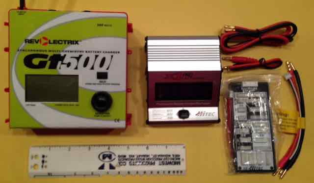
     The photo shows my Gt500, which isn't large at all, with the X1 Pro, its accessories and an 8" ruler.

     While setting up for the photo of the X1 PRO compared to the Gt500, I realized how small the 18AWG wire used on the charging cable is. Page 10 notes, &uqot;18AWG Wire Charging Cable". This cable is used for the charging cable from the charger to the battery's power lead. The photo, p. 10, clearly shows the cable to be short. It is about 6.5" long including the length of the banana connectors. The wire length between the connectors is 3.5".

     To begin using and testing the charger, I put Anderson Power Poles (APP) on the 18AWG Wire Charging Cable.

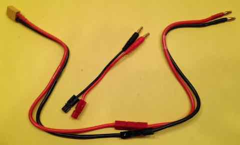
     I clipped the DC Input Power Cable in half and added Anderson Power Poles (APPs) to the clipped ends. I use APP connectors on my alligator clips from my Marine/RV battery to the charger. If another power supply is ever used with this charger, I wanted to keep the banana plug option available.

     The Power Cable half, with the banana plugs on it and the APPs, can also be used as a heavier duty 'battery' charging cable.

     I read through the well written manual one more time.

     With no power applied to the charge, I plugged the XT-60 DC Input Power Cable into its socket. I plugged the 18AWG Wire Charging Cable into its banana plug sockets. I plugged the Balance Adapter into the Balance Board and then into the Balance Socket, which is a 6S JST-XH. connector.

     Page 16 of the manual has a VERY IMPORTANT NOTE about plugging in the Balance Adaptor to the charger. "The balance wire attached to the battery must be connected to the charger with the black wire aligned with the negative symbol (-)."

     It is possible to hook up the 'wrong end' of the Balance Adapter. I know. Don't ask.

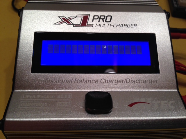
     Unfortunately, when I plugged in the charger it didnÕt work. It just showed a line of boxes going across the screen.

     I called Hitec/RCD and got a very positive response. I thought I'd have to send both units back through Tower Hobbies. Mike Mayberry said he'd just exchange the charger, as the power supply appeared to work. We made the arrangement for Hitec to send out the replacement charger on 12/12/2017.

     The replacement charger arrived on 12/15/17 by 2 Day Priority Mail. A prepaid return mailing slip was included.

     That is what I call SERVICE!!!

     I reread the manual again.

     On Page 12, Optimized Operating Software, it notes, "The X1 Pro "AUTO" feature sets the charge and discharge current for you automatically, preventing overcharging which can damage your battery."

     What it doesn't note is that this feature only applies to NiCd/NiMN batteries, p. 30. A person using Lithium based batteries could be confused.

     Actually a lot of the charger's features are for NiCd/NiMH batteries that are still in use by many 'car guys'.

     On p. 35, Pb CHARGE MODES, it reads, "The X1 Pro offers the following NiCd/NiMH charge modes: Charge and Discharge." It should read, "The X1 Pro offers the following Pb charge modes: Charge and Discharge."

     Unfortunately the explanations are not very clear for the System Setup starting on p. 42. The System Setup found in the SkyRC manual is a bit clearer, but not much better.

     It appears that the majority of System Setup changes relate to charging NiCd/NiMH type cells and peak detection for NiCd/NiMH cells.

     First I set up the 'new' charger on its companion power supply using the provided "double-sided" banana plug connectors between the power supply top banana sockets, which was unplugged from the AC and off, and the chargerÕs bottom sockets. No adapters or leads were plugged into the charger.

     The power supply was plugged in and then turned on.

     The easy to read, blue, LCD screen, with white characters, lit up.

     I used the printed manual to remind me how to navigate the various menus. Trying to read the printed manual also reminded me how very poor my vision is. Thank goodness I had a magnifying glass at hand.

     The power supply was then shut down. There is no On/Off switch on the charger. The Balance Adaptor cable and Balancing Board were connected correctly to the charger following the information on p. 16 of the manual. The banana plugs of the 18AWG Wire Charging Cable, with APP connectors at the other end, were plugged into their correct sockets of the Charging Output.

     The menu was easily navigated to LI BATT METER. A 3S 1000mAh standard LiPo pack was plugged into the Charging Cable and its JST-XH balance connector into the appropriate socket on the Balancing Board. The 'stick' was pushed to the right and voltages for each cell, 3.80V each, showed up on screen. Pushing the 'stick' forward showed the pack voltage of 11.41V and the high (H) cell at 3.806V and low (L) cell at 3.805V.

     Next a 4S 1100mAh A123 (LiFe) pack was attached. The voltages were 3.47V, 3.47V, 3.47V, 3.46V, pack voltage 13.88V, H 3.472V, and L 3.464V.

     The same 3S 1000mAh LiPo was put into LiPo BALANCE mode at 2 amps (2C) following the directions on p. 20 of the Hitec manual.

     During this charge, I accidentally stopped charger. While it was charging, I pressed the 'stick' up to note the individual cell voltages. Instead of pressing right to return to the main charger screen, I pressed the 'stick' down. A lot of interesting information was displayed. I should have pressed the 'stick' right to get out of that information, but pressed left and stopped the charger after about 8 minutes.

     I restarted the charger. It took about 18 minutes more to complete the charge. That was a total of about 26 minutes.

     Since the pack was not going to be used, I did a storage 'charge/discharge'. This was a discharge to storage voltage, since the pack was "full".

     The specifications note that the discharge power is 30W. 30W / 12.6V = 2.381 amps. I set the amps to 2.3A. The charger only allows amp input to the tenths place. The target storage voltage cannot be set.

     Shortly after starting the storage process, the fan came on.

     The charger stopped after 7 minutes and 39 seconds. It noted 11.38V as the terminated voltage. The individual voltages were not available on the FINISHED screen.

     The table on p. 7 of the manual indicates that LiPo Storage Voltage is 3.8V per cell. The SkyRC manual, p. 19 notes, "3.85V for LiPo".

     My repeated testing indicated that the charger software tried to terminate the discharge at 11.40V for a 3S LiPo pack. That is 3.8V per cell.

NiCd/NiMH Charging

     Next I wanted to check the NiCd/NiMH functions. Unfortunately, the only NiMH packs I have are small 4 cell receiver packs in the 800mAh range. They are generally charged at 1/10C rate. That is basically an over night charge on a 'wall wart' charger.

     I tried to charge two of these small 'receiver' packs. It didn't go well. They went 'over voltage' without the peak being detected.

     I believe my problem was noted in the manual on p. 30 where it says, "Some batteries of low resistance and capacity can lead to higher current in the Auto Charge mode."

     I do believe that they made a small error in the statement. I believe they meant high resistance and low capacity.

     I can really draw no conclusions about the charger's ability to charge larger capacity NiCd or NiMH packs used as power packs.

Output Ability

     To check the charger's output ability, a 6S 2300mAh A123 (LiFe) pack was used.

     Because I leave my A123 packs fully charged in their planes, the pack was discharged and allowed to rest over night.

     The charger was removed from the mating power supply and attached to an intentionally partially discharged 12V Marine/RV battery.

180W / (3.6V * 6 = 21.6V) = 8.33A

     Using the LiFe Balance Mode, the amps were set to 16. Heavy gauge leads were used by using the half of the DC Input Power Cable with banana plugs on one end and APP connectors on the other. I just had no 'faith' in the tiny 18AWG charing cable.

     During the constant current (CC) phase of the charge the amps rose to 8.5 and volts to 21.1. That is 179.35W. Impressive.

Charging a Pb (lead acid) Battery

     I have never used one of these multi-chemistry charges to charge a Pb battery before, as I never had a power supply. This was a first.

     From the recent use, the 12V Marine/RV battery had an open circuit voltage (OCV) of 12.54V.

     The charger was reinstalled on the power supply. I left my version the heavier gauge charge chord on. The Pb battery was attached to the charge cable.

     The charge terminated with the message "Over Charge Capacity Limit". It appeared to have reached the default the capacity limit of 5000mAh. That limit is found in the Set Up Menu.

     Two hours later the battery's OCV was 12.94V.

     The charge was started again.

     Within two minutes the volts reached 14.40V and the current dropped to 3.5 amps and continued to drop.

     The charge terminated with a TIME LIMIT warning at 2 hours (120 minutes). That is the default time set in the Set Up menu.

     After an over night rest, I put it back on the charger. Within two minutes the volts reached 14.40V and the current dropped to about 1 amps and moved up and down very slightly through the complete charge.

     The charge terminated with a TIME LIMIT warning at 2 hours (120 minutes).

     Shortly after the charge terminated, a Fluke multi-meter showed 13.62V.

     I decided that I'd had enough of trying to get the charge to terminate on this charger.

     I hooked up the battery to my NOCO charger. The NOCO went through its normal start up and within a few minutes it showed a solid green light. A solid green light indicates that it is 100% full. I have no idea when it reached this state with the X1 Pro, as the charge never terminated. It only ran out of time.

     Obviously, the charger can charge a Pb battery, but it is probably not the best option for doing so.

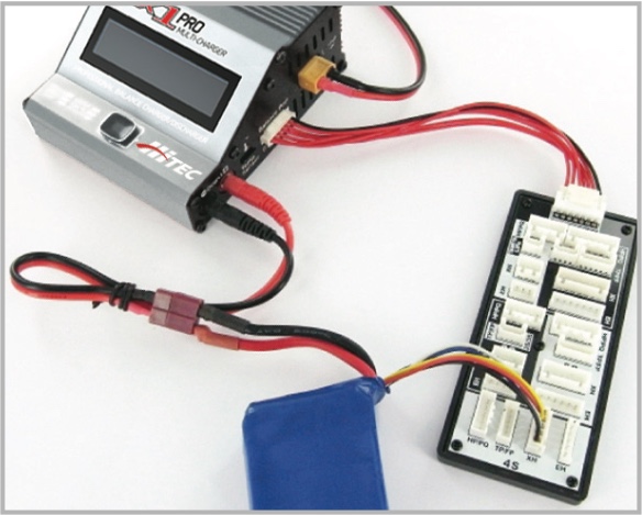
Parallel Charging (Advanced Skill Required)

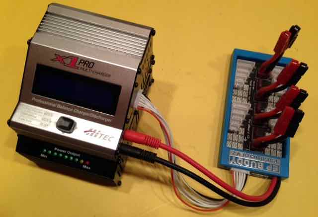
     My Buddy RC EP Buddy ParaBoard V2 plugs directly into the JST-XH connector on the side of the charger.

     With 180W of power out, this charger can easily parallel change 4 of my 3S 1000mAh LiPo batteries at 1 amps, which is 1C, while at home.

     Actually it could charge 180W / 12.6V = 14.29A
14.29A / 4 = 3.57A

     Up to four 3500mAh (3.5Ah) packs, charged in parallel, at 1C, which equals 14 amps, and could be handled by this charger.

     Beginner's, this is a best buy for you. Grab it while it is still available! Need a second charger? Go for it! :-)

Return to "What's In This Issue"

To Reach Ken Myers, you can land mail to the address at the top of the page. My E-mail address is: KMyersEFO@theampeer.org

EFO WEB Site