 |
Flying High With Electric Power!
The Ampeer ON-LINE!
Fly the Future - Fly Electric! |
Site Table of Contents
| President: | Vice-President: | Secretary/Treasurer: |
| Ken Myers | Richard Utkan | Rick Sawicki |
| 1911 Bradshaw Ct. | 240 Cabinet | 5089 Ledgewood Ct. W. |
| Commerce Twp., MI 48390 | Milford, MI 48381 | Commerce Twp., MI 48382 |
| (248) 669-8124 | (248) 685-1705 | 248.685.7056 |
 | ||
| Board of Directors: | Board of Directors: | Ampeer Editor |
| David Stacer | Arthur Deane | Ken Myers |
| 16575 Brookland Blvd. | 21690 Bedford Dr. | 1911 Bradshaw Ct. |
| Northville, MI 48167 | Northville, MI 48167 | Commerce Twp., MI 48390 |
| 248.924.2324 | 248.348.2058 | 248.669.8124 |
| Mailed Ampeer printed subscriptions are no longer available.
The Ampeer is FREE on-line in Acrobat .pdf format and HTML with active links! | ||
| The Next Meeting:
Date: Sat. Nov. 2 Time: 11:00 a.m.
Place: Midwest RC Society 7 Mi. Rd. field | ||
| What's In This Issue? | ||||
| Tactic Brand Radio: A Follow Up, Ken Myers presents follow-up information this transmitter and receiver. The article also includes how to set up a throttle cut safety switch. | More on the Tactic TTX650 and TR624 Receiver Joe Hass shares his positive experiences using Tactic TTX650 and TR624 receivers. | |||
| National Model Aviation Day Wounded Warrior Fundraiser Report Joe Hass reports on the event held at the Ultimate Soccer Arenas in Pontiac, MI | Upcoming November 3 Swap Meet Info Information on Midwest's upcoming Swap Shop in Northville, MI. | |||
| A Problem with a CellPro Balance Adaptor, Arthur Deane discusses a problem with the CellPro balance adaptor and the solution. | An Oops with My Maxford USA An-2 Ken describes an oops he had with this ARF and how he fixed it. | |||
| Do You Ever Read Stuff and Just Go, "Huh?", Ken Myers discusses why you should think while you read, AKA critical thinking skills. | ||||
By Ken Myers
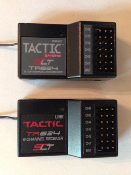
"The July 2013 Ampeer had a feature article on the Tactic TTX650 and companion TR624 receiver. At the time of this writing, I have had the TR624 installed in five planes. The total flights as of October 17 are 188. The planes range from a 34 oz. parkzone T-28 to the 98 oz. Maxford USA Antonov An-2. I have been very satisfied with the system and especially the ease of programming the Tactic TTX650. "There appear to be two versions of the TR624 receiver. The one with the word Tactic in white lettering and with the word bind near the link button appears to be the earliest version. The second version has the word Tactic in red lettering and the word link appears near the link button. Both have performed equally well for me. Tactic has added a new receiver to the mix. It is the TR625. It is physically different from the TR624 in that it has dual antennas, which should allow for greater signal diversity selection. The new TR625 is priced at two for $47.99 at Tower Hobbies. I should note again that the single antenna TR624 have been working well for me. Tactic has also added a Frequently Asked Questions (FAQ) section to the Support section of their Web site. The link above is to the FAQ for the TTX650 and includes:
Always set the failsafe after setting up a new receiver to the TTX650. The failsafe for the TTX650 using the TR624 only sets the throttle to 'off'. To set the failsafe, after setting up the transmitter and receiver, with both units on and the transmitter throttle stick in the off position, press and hold the bind/link button and watch for the flashes indicating the failsafe has been set. Check the failsafe operation. With the prop off, run up the motor a bit. Full throttle is not necessary. Turn off the transmitter. The throttle should 'shut down'. This indicates that the failsafe is operating. One of the things that I've always liked about my Hitec Eclipse 7 and Optic 6 is a button on the face of the transmitter that locks the throttle. This is a MUST HAVE safety feature for electric planes. I wanted that feature on my Tactic TTX650. To set it up, I chose the two-position switch H, which is located on the top right of the transmitter, to be my Lock "button". The "Lock" feature can be added when setting up a new electric plane or added to a preexisting plane. It must be added to each plane. It actually will take less than a minute to add this safety feature. Actually, it will take a lot longer to read how to do it, than actually do it! Enter the SETTINGS Menu for the desired aircraft Use the MINUS key to move to THROTTLE CUT Press the ENTER key The cursor box is at CTRL: Press the ENTER key "Chose the Control Switch" appears on screen Move Switch H "SH L:(0) H:(1)" appears on screen Press the ESC key to accept the default Move switch H so that CTRL: SH ON appears on the screen
Move the cursor box to TRIG: press the Enter key. Nothing will appear to happen, but the default 10% is selected. Move the cursor box to CUT.: Press the ENTER Key, reduce to 0% using the MINUS key, press the ENTER key The Throttle Cut is now set as a throttle lock. The graphic on the right side of the screen shows no movement when the throttle stick is moved and the screen shows CTRL: SH ON. Push switch H back toward the rear of the transmitter and the screen shows CTRL: SH OFF The graphic moves with the throttle stick movement. If the Tactic TTX650 is turned on with the throttle sick anywhere but 0% a Warning Box appears on the screen that says "THR CUT CONTINUE YES" and the transmitter beeps. Press the ENTER key or move switch H rearward to remove the warning box and stop the beeping. It may be necessary to have the throttle "Lock" off to arm the speed control. Don't forget to turn it back on after arming. The programming must be done for each plane and is really a MUST DO safety feature! We have a lot of the Tactic TR624 receivers performing well in our club. There has been almost no problems with them, but... Midwest president, and EFO member, Arthur Deane did find a faulty TR624 while performing a range check of a freshly installed, new TR624 in his Clouds Fly. A different, new TR624 was installed in the aircraft. The failsafe was set and it easily passed the range check. With the new, new receiver installed the plane flew well and under control at all times. The defective receiver was exchanged by Hobby Services of Hobbico. From Joe Hass, via email Since many of the aircraft I have flown with the TACTIC TTX 650 have been small and electric, I have had a lot of questions about the compatibility of the TACTIC transmitter and receiver with larger aircraft and glow power. Today (Aug. 20, 2013 KM) I flew my 64", 9 pound OS .90 powered Crossfire sport pattern aircraft. It uses a lot of sky. The landing pattern can extend past the high tension wires on the east side of the (Skymasters) field. I have also flown a .46, 68" wingspan amphibian Laker. The receiver is below the water line during taxi, take off and landing. I am satisfied with the performance. Joe Hass The Flyzone Tidewater from Hobbico has proven to be a great aircraft for flying off water. I hope you enjoy the write up and video at www.modelaviation.com/flyzonetidewater. The Tactic wireless Buddy Box is a great way to "get your feet wet" when it comes to float flying. I will be happy to let anyone fly mine. Thanks to all for the help in getting the pictures and video. Thanks to Roger Schemmling for letting me assemble his Tidewater, as mine was already put together before I got the assignment to do the review. John Hoover at Flight Line Hobby (Lake Orion, MI) has the Tidewater and Tactic systems in stock. Give the Tactic 650 Transmitter a good look. It has tons of features and a great price point. Enjoy!
From Joe Hass, via email
The first National Model Aviation Day was an overwhelming success with $2,160.00 raised to benefit the Wounded Warriors Project. This event was a unique combination of both Free Flight and Radio Controlled fixed wing, 3-D, helicopters and quadcopters all held in the beautiful facilities at Ultimate Soccer Arenas in Pontiac, MI. 68 pilots enjoyed air conditioned comfort and flew for 4 hours. George Derderian, one of the principals at Ultimate, was on board immediately when I asked for his help. Ultimate provided 2 turf covered fields, over 120,000 square feet of flying area, and a meeting room at no charge. Hobbico joined in support by providing a plethora of prizes. Local retailers including John Hoover at Flight Line Hobby, Chris Wrigley at Nankin Hobby, Matt Brubaker at Prop Shop Hobby as well as Mark Freeland of Retro R/C and Max Ettinger of Park Models all made major contributions. Even though this was an indoor event Merlin Glow Plugs of Western Springs, IL wanted to help the cause and donated gift certificates and merchandise recognizing that many of the participants also fly outdoors. While an event flyer was put together and distributed throughout southeastern Michigan the biggest publicity boost came when I had an opportunity to speak on air with Frank Beckmann on the 50,000 watt radio station 760 AM. I had 5 minutes to share with Frank and his audience everything that was going to happen and the great cause that would benefit. I know it worked because folks from as far away as Lansing and Toledo stopped by to see first hand what model aviation is all about and make a contribution. After the Pledge of Allegiance Davis Gloff, a member of the Cloudbusters, sang the National Anthem. Davis is an active modeler, singer, songwriter and actor with credits including the movie Gran Torino. A group picture was taken. Tim Jesky, our AMA District 7 VP was airborne flying to South Africa to watch his son Andrew fly at the World Championships. Tim asked me to read a short message to the participants. Simultaneously the new managers of the World Cup Grill open up the restaurant for great food. Now it was time to fly. About 1 PM I shut down the flight line for some demos. First up was the new Flyzone P-38. Folks were amazed that it not only took off from the "turf" but landed and taxied back. You can fly a twin in the amount of time that it takes to charge the single cell lipo.  Chris and I then flew a pair of the new Heli-Max Blackhawk helicopters. This is a beautiful rendition of the Blackhawk with a flybarless 4 blade rotor system and gyros. It can handle wind and performs very well, especially in the hands of a skilled pilot like Chris. Two pylons were then added to center stage for the "slowest" race possible. To the music from the movie "Those Magnificent Men and Their Flying Machines" 4 pre WWI replicas (2 Antoinettes, a Demoiselle and a Deperdussin) were flown by Bill Brown Sr. and Joe Hass, Bill Brown Jr. and Mark Freeland. The breakneck speed resulted in an astounding 3 laps in the 2 minutes the song played. Neat to see aircraft so big flying so slow. There was time set aside for all balsa airplanes so that the "builders" could fly in unobstructed air. Other demos included the Great Planes flat foam Citabria and the "flying pizza box" ERAZE. The ERAZE is hard to describe except that it is really cool and, when equipped with a 600MAH 3 cell lipo will go straight up while rolling. It is a lot tamer with 2 cells. Suffice to say that it was FAST. Chris and I then took up the Flyzone SE-5 and Triplane for a bit of Snoopy and the Red Baron flying. The Quad Copter Obstacle Course included a horizontal chicane, a vertical chicane and a rotating hoop that the quad had to fly through. It was a challenge but fun. At this writing I havenŐt had a chance to see the "course video" recorded on the 1SQVM (a Heli-Max1SQ quad copter with an on board video camera all in the palm of your hand). Jim Held organized a "satellite event" at the Romeo Skyhawks field. First prize there was a chance to fly his giant scale P-51 ŇOld CrowÓ. This provided a major contribution and a lot of fun. Throughout the event over $1,000.00 in prizes were presented to pilots and donors. There are so many stories about neat people winning neat prizes. One of the free flight pilots won the Parkzone RTF Archer. He always wanted to fly R/C. The two TACTIC 650 transmitters and receivers were won by Bill Stark and Jim Wynn. Bill wasnŐt at the event so I called his cell. His wife answered, explaining that Bill was driving and he would call me back. I explained what he had won a radio and she said "He will talk to you now!" His excitement, as well as Jim's was palpable. My thanks go to the members of M.I.A.A., George Maiorana, Jim Held, Steve Fredericks, Fred Engelman and others who helped. Walt Plentis (the guy who flies the full size J-3 on floats at the September float fly) and his son stayed around to help with tear down. Chuck Adams and Amy Copland of PMAC helped too. A special thanks to my wife Paula who left her crutches in the car to man the registration area and tolerated 3 months of loosing the living room and dining room to "model aviation". She had already lost here spot in the garage to Chris' 35% aircraft. Joe Hass From Rudi Reinhard, Swap Meet Chairman Midwest RC Society
Sunday, November 3, 2013
location
admission charge
vendor table cost
For Information
directions Take the 8 Mile Road exit off of I-275 Go west 2.5 miles to Center Street Go south on Center Street 0.5 miles to Main Street Go west on Main Street The Northville Senior Community Center is located at 303 Main Street in downtown Northville There is free parking in the back of the building off of Cady Street. THIS IS THE BEST AND LARGEST SWAP MEET IN SOUTHEASTERN MICHIGAN! From Arthur Deane via email I recently had a problem using a CellPro charger adaptor. A 4-cell battery would charge but a 2- or 3-cell battery would not. I received an alarm "battery not connected". I measured the battery voltages on both the power and balance leads. The battery voltages were correct. By process of elimination the problem had to be in the balance adaptor. Using a blade I opened up the back of the adaptor over the balance connector that was not working and found that the copper circuit strip had delaminated from the circuit board and broken. I have to assume that when connecting and disconnecting the balance leads I had pressed the adhesive backed foam spacer on to the circuit board (2). When I removed the finger pressure, the foam pad returned to its original position and pulled the copper circuit bar from the board and broke it. See sketch. (3) 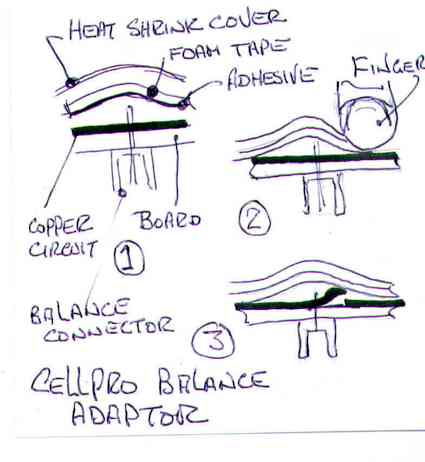 The problem was corrected by scraping the insulating coating to expose the copper bar and then soldering a jumper across the break. See photo. 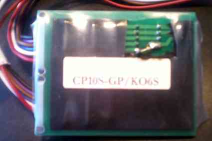 I wanted to use the solder wire as a jumper but without precise heat control and a steady hand it simply melts. I had to make a jumper out of an old servo wire. Finally replaced the foam insulator with adhesive side away from the board. Apparently CellPro added the foam pad to prevent the connector wire projecting through the heat shrink cover. That was a good fix, but they now need to delete the adhesive. It is not needed. The heat shrink will keep the foam pad in position. By Ken Myers I had a major 'oops' with the Maxford USA Antonov An-2 on August 9 on its third flight of the day. I believe that I was feeling cocky. The first two flights were perfect with good, upright, landings. I broke my cardinal rule; no crosswind takeoffs. I lost sight of it behind the cars behind flight line and it hit hard on the nose. The end result was a lot of broken 'stuff', but not the basic airframe structure. The fiberglass cowl cracked in many places, but did not break. The vacuum formed plastic motor and air scoop cracked and both were missing pieces. The motor mount fractured and became a total jigsaw puzzle. Amazingly, the other 'stuff' that 'broke' were just parts that hold things together. ĘMost of the parts just came 'unglued'. All of the 'unglued' parts were in really good shape.The glue joints simply failed. If I didn't have to do wing surgery to glue the Maxlok key tabs back into the upper wing panels, no covering would have had to been replaced. ĘOne of the tabs that pulled out looks like it had absolutely no glue on it at all. The transmitter should provide a warning if the selected model does not match the aircraft the 'receiver' is in that is to be flown. I thought a strut broke, but it didn't. ĘIt just separated at a construction joint near the top of the strut where it widens and rounds to attach to the wing. The radio, servos, and electronic speed control (ESC) all checked out okay. The motor needed a new prop adapter and shaft. See "Heads-up On the O.S. Motor OMA-50xx-xxx Motors" in the October 2013 Ampeer to see why I had a problem replacing the shaft. A full description of the repairs is located at theampeer.org/ampeer/ampnov13/An-2-repair.pdf for those who want all the gristly details. After the repairs, the plane seemed to fly even better than before. I still enjoy flying it. 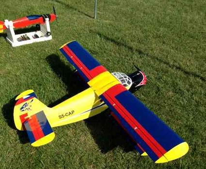 The photo shows the new red bands paralleling the top center section. The bands cover the open Maxlok key tab surgery and some balsa repairs on the top sheeting. By Ken Myers I was given an issue of a fairly current, October 2013, RC flying magazine. There was a new E-Power column in it. I was curious as to how good it might be and what 'direction' it might take. I read the column several times over, as well as the captions to the graphics. I really wanted to let my observations go without comment, but I just couldn't. First, let me say that I have made many mistakes in the Ampeer over the years. Some I have caught and some were caught by you, the Ampeer readers. I try my hardest not to publish misinformation, but it does happen, and it has happened to me. Starting on p. 47, the author described an electrically powered sport twin.
I calculated the the wing cube loading and stall speed. Wing Cube Loading (WCL) = 152 oz. / (5.5 sq.ft. ^ 1.5) = 11.8, which places it in the advanced sport category difficulty to fly level.
Category levels information is found on the tab labeled disk load.
The author noted that it uses two Emax BL2826 outrunners. The Emax BL2826 weighs between 182g and 193g (depending on the source) and has a stated Kv of 850.
He noted that the props used are a 12 x 6 slow-fly-type. The photos of the plane show what looks like APC 12x6SF props. He stated, near the bottom right column on p. 47, that the Kv is 850, and then, out of nowhere, with no supporting information, stated that the propellers turn at about 8000 rpm at full throttle. Huh? APC recommends an RPM safety limit for their props. For the SF props their recommended RPM limit is Maximum RPM = 65,000/prop diameter (inches)
8000 RPM is about 2600 RPM over the limit, based on their recommendation, for an APC Slow Flyer Prop, if the prop is indeed an APC prop. There was a description of how the plane is usually flown, and full throttle is hardly ever used. I mention the RPM limit only because it could be a problem when 'bench testing' the battery, motor(s), ESC(s), prop combination. It takes about 600 watts OUT to turn an APC 12x6SF at 8000 RPM. (For the APC 12x6SF prop the Drive Calculator Exponent is 3.3 and the Factor is 0.6289999
Prop calculations for the power required to turn at a given RPM are only approximate, but usually reasonably close. I verified the Exponent and Factor numbers by comparing the Drive Calculator predictions for the APC 12x6SF prop using Scorpion and Cobra measured motor data at the Innov8tive Designs' Web site. The Drive Calculator predictions, in each instance, were quite close to what Lucien Miller measured with a constant voltage power source. One Verification Example of the many I looked at for the APC 12x6SF: Innov8tive Designs' Data for the Scorpion SII-3020-780, 11.1v, 40.04 amps, 444.4 watts in, 6,750 RPM Drive Calculator Prediction for my elevation, 287m and a temperature of 20-deg C. Scorpion SII-3020-780KV, data input by www.litronics2000.de (www.elektromodellflug.de), 11.1v, 41.2 amps, 457 watts in, 6754 RPM The article states that a 3S 5300mAh LiPo is used for each motor and the maximum current draw is 38 amps per motor. I calculated that 11.1v (3S Li-Po voltage with an unknown amp draw) * 38 amps = 422 watts in. Even at 12.6v (3S Li-Po fully charged voltage) * 38 amps thatŐs only 479 watts in. The watts in are not close to the required watts out to turn an APC 12x6SF at 8000 RPM. Huh? The author talked about the relationship between Kv and RPM on p. 50. He noted that the term Kv defines the speed an electric motor will turn for each volt applied to the inputs. After that first statement, he clarified it further by noting that this is with respect to its no-load condition without a propeller. Huh? This is somewhat true, but stated a bit 'oddly'. The approximate Kv (RPM per volt) can be found by dividing the no-load RPM by the input voltage.
There are losses in the electrical system. To illustrate why dividing the no-load RPM by the input voltage is only approximate, I'll use my recently tested O.S. Motor OMA-5010-810 brushless outrunner motor. The numbers presented come from collected data using an Emeter II.
The Kv, using the method stated by the column's author, is 11,341 RPM / 14.48v = 789 Kv, which is pretty close to my measured Kv. This is the method used by the so called electronic Kv testers. 14.48v (measured input voltage between the ESC and battery) * 800Kv (my measured Kv) = 11,584 RPM Where did the 243 RPM (11,584 - 11,341) go? The reduction in RPM is mainly due to the voltage drop because of the current flow of 1.82 amps and the resistance of the motor, ESC, wire and connectors. That is about a 0.3v (243 / 800) drop with no load. As the amps go up, the voltage drop increases. Continuing his discourse about Kv, the author noted that when a propeller is fitted to the motor, the actual rpm will be somewhat less. Then he added more information by noting that typically a motor will achieve approximately 85 percent of its no load speed. Huh? For his example, he used 850Kv times 11 volts (not explaining why 11 volts) times 0.85 (85%) for 7947 RPM and then rounded up. This explained where his 8000 RPM number was derived, which had been presented earlier in the text with no explanation. The number of volts applied at the ESC for a brushless system varies with the current flow, which is determined by the load. Other factors affecting the voltage include the state of charge of the battery, the condition of the battery and its internal resistance or impedance which is related to the 'C' rating. Also, the load varies even with the exact same prop. The elevation above sea level, the air pressure and ambient temperature affect how much load is placed on the motor by the same prop. It is a somewhat common practice to guesstimate/approximate a Li-Po battery's voltage under load using 3.7v per cell. Therefore a 3S Li-Po would be 11.1v, which is close to his 11v figure. The voltage depends on the actual current flow and the point in time of the power meter reading during the discharge, the condition of the battery, and the batteryŐs internal impedance (resistance). Any voltage chosen is a compromise and only a snapshot of one point in time. We are trying to guess what it might be at some point, but it is a moving target, literally. I recently captured data, with my Emeter II, for the previously noted O.S. motor at about 10 seconds into the motor run using a 4S "A123" 2300mAh battery.
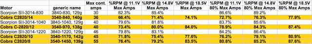
To me, an 1800 RPM drop from about 8900 RPM is a bit more than the 'somewhat' stated by the column's author. 85% of the no load RPM/voltage can be a bit overly optimistic for a 'rule of thumb'. Motors with less mass (small motors) are generally less efficient and the percentage can be expected to move down, while motors with greater mass (large motors) are generally more efficient and the percentage moves up. Using the Drive Calculator exponent and factor for the APC 12x6SF at 7947 RPM (the author's calculated RPM) yields 588 watts out, or being absorbed to turn the prop, at that RPM. The 11v he used in this formula times the given 38 amps yields a watts in of about 418. That means, using his formula for his RPM, this motor is over 140% efficient. Huh? If the motor were 100% efficient then 418 watts in would also be the watts out / 0.6289999 (the factor) = 664.55 ^ (1/3.3) = 7166 RPM. 1/3.3 is the inverse of the exponent 3.3. I would expect the actual RPM to be less than 7166. Without having the actual motor in-hand and not knowing exactly what prop it was, it is difficult to really guess about it. I do believe that the actual RPM will be much closer to, or less than, 7000 rather than the stated 8000. An often repeated 'rule of thumb' is that a good place to run a given motor is at a certain percentage of the no load RPM. This rule of thumb does not hold up. It is true that at about 50% of the no load RPM the motor is running at about 50% efficiency. That is a point to stay away from! There is no correlation for any other percentages based on the no load RPM. The percentage of no load RPM varies with the number of cells and the efficiency of the motor, as well as what 'amps' the operator wants the motor to draw statically at full throttle. Two similar motors were chosen to illustrate that there is no reason to use a percentage of the no load RPM to try and predict a good RPM usage point for a motor. The chosen motors have approximately the same weight and Kv. The Scorpion 3014 series has an outside diameter of about 38mm and an approximate length of 40mm, and it has a given weight of 129g for the three different winds. The Cobra C2820 series has an outside diameter of about 35mm (3mm shorter than the Scorpion) and an approximate length of 40mm and, it has a given weight of about 139g for the four different winds. It is easy to note the percentage of the no load RPM differences between the two motors and that the only consistent thing is that the percentage of no load RPM increases with the number of cells. |

|
According to the data on the Innov8tive Designs Web site, the Scorpion SII-3014-830 can swing an APC 11x8.5E at about 7,613 RPM with an input of 11.1V. The amp draw is given as 30.49 amps for 340.8 watts in. The approximate computed watts out is 251 for an efficiency of 73.7%. 7,613 RPM is 82.6% of the 9213 no load RPM. The Cobra C2820/14 can swing an APC 12x10E at 6,617 RPM with an input of 11.1V. The amp draw is given as 30.74 amps for 341.2 watts in. The approximate computed watts out is 233 for an efficiency of 68.2%. 6,617 RPM is 71% of the 9,324 no load RPM. At the rated maximum amps the percent of the no load RPM gets even lower, as well as the efficiency. After looking at all the information and data that I collected, I contacted the author via email. He looked at some of the information that I provided about what I feel is an erroneous 8000 RPM and has removed that number from the article about the plane on his Web site. HeŐs going to try and verify the actual RPM with the owner of the aircraft in the article on his Web site. Lastly, while doing some research on a diagram that was presented on p. 47 regarding using water flow to describe electricity, I found a very interesting site called "DC Circuit Water Analogy". Maybe, when you read this, you too said huh to my writing. Think while you read. Yes, I do know that many of you read my 'stuff' and just go, "huh", but all I ask is that you think about it. |
To Reach Ken Myers, you can land mail to the address at the top of the page. My E-mail address is: KMyersEFO@theampeer.org