 |
Flying High With Electric Power!
The Ampeer ON-LINE!
Fly the Future - Fly Electric! |
Site Table of Contents
| President: | Vice-President: | Secretary/Treasurer: |
| Ken Myers | Richard Utkan | Rick Sawicki |
| 1911 Bradshaw Ct. | 240 Cabinet | 5089 Ledgewood Ct. W. |
| Commerce Twp., MI 48390 | Milford, MI 48381 | Commerce Twp., MI 48382 |
| (248) 669-8124 | (248) 685-1705 | 248.685.7056 |
 | ||
| Board of Directors: | Board of Directors: | Ampeer Editor |
| David Stacer | Arthur Deane | Ken Myers |
| 16575 Brookland Blvd. | 21690 Bedford Dr. | 1911 Bradshaw Ct. |
| Northville, MI 48167 | Northville, MI 48167 | Commerce Twp., MI 48390 |
| 248.924.2324 | 248.348.2058 | 248.669.8124 |
| Mailed Ampeer printed subscriptions are no longer available.
The Ampeer is FREE on-line in Acrobat .pdf format and HTML with active links! | ||
| The Next EFO Flying Meeting:
Date: Sat., Sept. 7 Time: 10:00 a.m.
Place: Midwest RC Society 7 Mi. Rd. field | ||
| What's In This Issue? | ||||
| Maxford USA Antonov An-2 ARF, assembly tips and review by Ken Myers. | ||||
By Ken Myers August 2013 Forward: Sometime during 2010, I became interested in making a model of the Antonov An-2 Colt. In December of 2010 I started drawing up the plans for an Antonov An-2. I even went so far as to make up some proof of concept models for some of the more difficult design areas. I found that the 3-view that I was using from the Internet was not as accurate as I wanted. Two years ago I purchased a better set of views while at the Toledo RC Expo. My goal was to redraw my plans for my large scale An-2. This year, in April 2013, while at the Toledo RC Expo, Roger Wilfong told me about an An-2 ARF that was being sold by Maxford USA. I immediately went to their booth and looked it over. While not as large as I was planning on, and not very accurate, I thought that I might learn some design ideas from it. I pre-purchased the An-2 on April 5. I was told that it 'might' be available in a few weeks to a month. It finally became 'in stock' on their Web site just after Memorial Day, May 27. I called Maxford USA on May 29 and was told that each kit was being checked over before shipping and that they would be shipped in the order that the pre-orders were received. I called again during the first full week of June and was told that my order would be shipped soon. I called at the beginning of the second full week of June and was told that the order filler was ill. It was shipped on June 10 via UPS, but I never received a tracking notice. I emailed later in that week and was given a tracking number. It finally arrived here in the early evening of June 20. There was no physical damage on the shipping box, so it was not opened until the morning of June 21. The outside corrugated box and inside corrugated box were in perfect shape. There were no indentations, punches or cuts in either box. 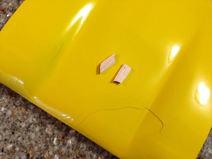 The first piece that I removed was the top wing center section. The 'plastic' top of the center section was cracked in two places. There were also two pieces of balsa floating around in the center section and obviously rattling when I turned it over to look at the bottom of the section. I was able to get one piece to fall out and the other required a straight pin and needle nose pliers. The cracks and 'extra' pieces can be seen in the photo. I believe the quality control guy must have missed them. I did absolutely nothing to embellish the cracks. They are exactly as received. 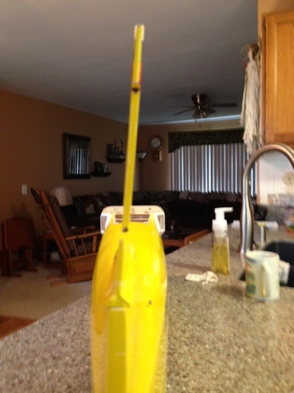 The triangle stock glued to the bottom of the vertical fin is 'crooked' and is not tapered to match the fuselage. The vertical fin, as received, was then taped onto the fuselage. The results can be seen in in the photo. 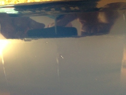 There were three dents in the covering of the top right wing panel. That is not a 'big' deal as a covering iron popped them right out. They were packed in a light foam wrap. I mention it only because, obviously, something hard was pressing against them the way they were packed in the box. The top leading edges of both bottom wings were not 'ironed down' around the leading edges. The film could easily be 'lifted' with the fingers. While the covering iron was out and hot, I 'fixed' that issue as well. There is not a complete packing list and parts identification provided. The brief, and barely adequate, manual was used to identify as many parts as possible. I created a parts list and have it available as An-2-parts-list.xls. While sorting and identifying all of the parts found in the kit, they were weighed on a triple-beam balance scale that measures grams. The total weight of the provided parts for the airframe is 1782.9g, 62.89 oz., or about 3 lb. 15 oz. That was 11 oz. under what Maxford USA listed, 4 lb. 10 oz. Of course that weight does not include the weight of any glue. The only thing found to be missing was one small wheel collar for the tailwheel assembly. The wood screws are noted as being 5/16" long in the manual. All of the provided wood screws measured 3/8" from the bottom of the head to the tip. There were two different diameters. That was not noted anywhere in the manual. The larger diameter appears to attach the main landing gear straps, as shown on p. 7 of the manual, and the rest, of smaller diameter, appear to be used when 5/16" wood screws are called out for in the assembly. On Friday, June 21, I emailed Maxford USA about the problems I had discovered. On Monday, June 24, the new center section arrived in the postal mail. Wow, what fantastic service! A funny thing happened on the way through the assembly. It turned out that Greg Gimlick had just completed the assembly of this model and was awaiting delivery of the motor that he'd chosen. It is a Cobra 4120-12, 293g, 850Kv outrunner. We began a series of emails regarding the assembly. It should be noted that Greg's kit did NOT have many of the problems that I found in mine. His upcoming review in Model Aviation will probably be quite different than this one. Assembly started on June 25 by coating the inside, front joints of the adjustable motor box with 30-minute epoxy. On page 2 of the manual, "Safety Precautions and Assembly Tips", "10. You may use 30-minute epoxy to attach critical parts...&quoit; and on page 3, "2. Items you must supply - 5-minute epoxy, cyanoacrylate (CA)..." 30-minute epoxy is really a better choice for many reasons. The first step in the manual, on p. 4, is to install the rudder and elevator servos. The pre-installed pushrods are solid wire inside a red plastic outer sleeve. I found that the elevator pushrod took extreme force to move it, and I do mean extreme! The rudder pushrod was only slightly better. I removed some of the bottom covering at the tail so that I could inspect where the elevator pushrod entered the fuselage. I found that there is an extremely sharp curve/bend where the outer sleeve exits the fuselage. The binding is there, at the sharp curve/bend. 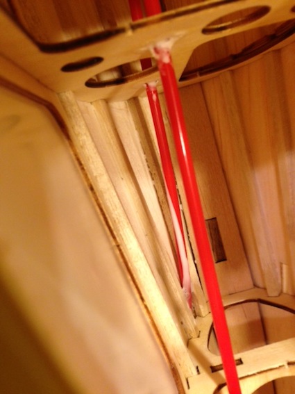 The sharp bend can be seen in the rod with the whitish glue smeared on it on the left in the photo. To eliminate the binding, I decided to replace the pre-installed, and unusable, pushrod with a Sullivan Flexible Gold-N-Rods Stock #504. This required a whole morning of work with a soldering iron, Dremel rotary tool, razor blades, X-acto handle and #11 blade and drill bits. To be sure that my replacement pushrod had the correct angle and no "S" bend, it was necessary to temporally install the elevator control horn, horizontal stabilizer and elevator at this time. The control horn backplate was prepared for use by running a 1/16" drill bit in a pin vice through the holes on the plate, threading a provided 3/8" small diameter wood screw into the hole and then screwing one of the short machine screws through the hole. The process provided the threads in the nylon backplate for the machine screw. I did all six backplates at this time. The photo in the manual shows the servos in the rearmost position in the servo try. The newly installed red outer pushrod sleeve was trimmed to allow for this placement. The servo placement has since been changed by Maxford USA to the forward holes.There is a manual addendum available on the Maxford An-2 site. The wire elevator joiner was sanded and then the two elevator halves were joined using epoxy. Wax paper was placed between the elevator and horizontal stabilizer to keep them from sticking together. The whole assembly was then taped firmly to the flat building board. The tailwheel assembly was assembled and tailwheel wire 30-minute epoxied into rudder. The new center section had about a 1/8" lip/overhang that would have covered the wing panel joints very nicely. Unfortunately, the lip was hanging down and it would not allow the wing panels to seat to the center section. The lip was removed. The left and right wing panels were hinged using the Monokote/X-type hinging method. A photo of this hinging method is found at www.rcgroups.com/forums/attachment.php?attachmentid=1458836 A red stripe was added to the top and bottom of the wing panels to conceal the hinges. The same method was used on the horizontal stabilizer and elevator and on the vertical stabilizer and rudder. With only a little time to work on the plane, only a little more hinging and striping was done the following day and it was finished on Thursday, June 27. The self-adhesive graphics were trimmed and placed on the fuselage, cowl, bottom of the left wing panel and vertical stabilizer/rudder. Before the horizontal stabilizer could be 30-minute epoxied to the tail, the lower wing fairings and lower wings, according to the manual, were to be fitted to give a visual alignment for the horizontal stabilizer. The rear stub tube on the lower right wing fairing would not go into its hole in the fuselage. The hole was enlarged slightly and carefully with a file. 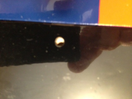 A bigger problem was that the tab for the Maxlok key, that is glued in the lower right wing panel, was not inserted to the correct depth into the wing. This caused the misalignment which can seen in the photo. The hole in the tab was filled with a piece of dowel and then a new hole drilled in the correct location for the Maxlok key insertion. The lower wing fairings were glued into place using the stub tubes and Titebond glue with Gorilla glue on the inside. The lower wings were fitted and Maxlok Keys inserted. Actually, I found that leveling the plane to the building board using the top wing was easier. The covering material was removed from the horizontal stabilizer where it would be glued to the fuselage. The horizontal stabilizer was then epoxied on using the building board to measure from and the top wing as a visual aid. On Friday, June 28, it was time to deal with the vertical stabilizer problem. The vertical fin with the previously hinged rudder was trial fitted. The covering was removed from the top of the horizontal stabilizer where the vertical fin would be glued. Without trying to correct the problem with the 1/4"-triangle stock on the right side of the vertical stabilizer, it was 30-minute epoxied to the fuselage and horizontal stabilizer. It was aligned vertically using a 90-deg triangle. Later, the gap, created by the misaligned 1/4"-triangle stock was filled with 30-minute epoxy. The rear of the 1/4"-triangle stock was not tapered to match the angle of the rear of the fuselage and 'hangs over' the rear of the fuselage on both sides. The installation of the aileron and flap servos came next. Maxford USA recommends Hitec HS-55 servos all around. Why they would recommend an 8g 15 oz-in servo for a six pound airplane is beyond me. The prototype photos, in the manual on page 9, definitely do not show Hitec HS-55 servos. In an email, Greg said that he had good luck, in four other planes, with the Power Up 12g Digital Metal Gear Sub-Micro Servo. It is a 'metal gear' (well sort of) 12g 30.8 oz-in servo. Unfortunately, I did not pay attention correctly to the name in the email and ordered the analog version, the Power Up 12g Metal Gear Sub-Micro Servo. It is a metal gear (well sort of) 12g analog 30.8 oz-in. They fit the servo mounts as provided for the ailerons and flaps and the servo tray in the fuselage. The Power Up servos look very much like the ones in the photos on p. 9 of the manual. The servo mount pedestals were attached to the servo plates using 30-minute epoxy. A new Tactic TR634 receiver was linked to a Tactic TTX650 transmitter and all of the servos tested using a 4.8V receiver battery to power the receiver. Holes were drilled for the 4-40 bolts and blind nuts in the adjustable motor box face. A 4-40 blind nut was slightly threaded onto a 1-1/2" 4-40 bolt and the blind nut pulled into position to enter the hole. A toothpick was used to place 30-minute epoxy under the blind nut and the 1-1/2" bolt pulled the blind nut into its hole while needle nose pliers were used to press it in from the back. Very carefully the 1-1/2" bolt was exchanged for a 1/2" 4-40 bolt and washer and the blind nut screwed firmly into position. Once the blind nut was in position, the 1/2" 4-40 bolt was removed until the epoxy cured. This task took much, much longer than I thought it would. It was difficult to figure a good method to use to get the blind nuts into the confined space of the adjustable motor box. Unfortunately the face of the motor box, where the motor's "+" mount is attached, is NOT good birch aircraft plywood. The type of plywood used has not held up well for me in the past. Once the epoxy cured on the vertical stabilizer, the remaining X-type hinges on the rudder were ironed onto the fuselage rear and the red trim stripe applied over them. The tailwheel bracket was screwed onto the fuselage with two small diameter 3/8" wood screws and the wheel collar tightened onto the tailwheel landing gear wire just below the bracket. The rudder control horn was mounted using the holes already in the control surface and then screwing the short machine screws through to the prepared backplate.  The rudder servo was installed first using the supplied pushrod and EZ Link. The servo was too low when setting in the servo tray and it put another bend and bind in the already binding rudder pushrod. The offending preinstalled rudder pushrod was removed with as much vexation as the elevator pushrod and replaced with another Sullivan Flexible pushrod. I found that the control horn on the elevator needed to be repositioned and angled to the angle of the pushrod and aligned to the hinge line. The rudder control horn was also repositioned and moved forward so that the holes in the control horn aligned with the rudder hinge line. The control horn also had to be trimmed near the bottom most hole to allow proper movement of the rudder. By this time, I had been in contact with Maxford USA about the problems I was finding with the assembly. Curt Sidles, of Maxford USA, called in the afternoon. He was very concerned about the quality issues in the kit that I had found and was going to immediately check inventory to see that the issues are taken care of before other kits were shipped. He also started writing the addendum to the manual, so that others would not run into these same issues. It seems to me that Maxford USA is very concerned about putting out the best ARF possible. They are definitely concerned with consumer support and very responsive to customer feedback. Saturday, June 28, was started by completing the new rudder pushrod installation. The control horns were attached to the elevator and rudder in their new locations. The elevator servo was installed in the original tray position, but the rudder servo required a 1/4" 'pedestal' on each end of the servo so that the pushrod had a straight run. The servos were hooked up to the radio system and a 4.8v NiMH receiver pack. The elevator throw could not be reduced physically because of where the pushrods were pre-located. Dual rates were used to reduce the elevator throw. The rudder throw appeared to be okay. Both servos were checked for proper throw direction. The motor shaft opening in the cowl was opened with a sanding drum in a Dremel rotary tool to allow the motor shaft to protrude. The motor mount box installation was started. It was very handy not having it installed while setting up the pushrods and servos. The motor mount box needed a lot of sanding to fit into the fuselage opening. On Sunday, June 30, more sanding was completed on the motor box for a good fit. The motor was temporarily attached to the motor box. The cowl was fitted and the holes drilled for the two 3/8" small diameter screws on each side using a pin vice and 1/16" drill bit. The cowl was removed and the motor box marked. The motor was removed from the motor box. 30-minute epoxy was applied to the motor box from the line marked on it to the rear. The motor box was reinserted to the marked line. Whenever possible, I like to use a proven radio system in a new plane. Therefore, a new red label Tactic TR624 receiver with the word LINK on it was wrapped with two bands of Scotch tape, to keep the receiver back from separating from the front. Velcro was attached to the rear of the receiver and then the new receiver was hooked up in the Thunder Tiger Lazy Tiger Club trainer. The previously flown white label Tactic TR624 receiver with the word BIND on it, with 20 flights on it in the trainer, was used as the receiver in the An-2. Later, the 'new' receiver was tested in the trainer and found to be working well, but better safe than sorry. The aileron and flap servos were setup on the bench with the receiver to verify how to set them up in their positions in the top wing; ailerons arms on opposite sides and flap servos, when using a "Y" harness, have the arms on the same side. The aileron servos were installed. Double-sided tape was placed where the servo would go on the servo hatch cover. The servo was positioned and pressed to the double-sided tape and the wood screws, that were provided with the servos, were screwed into the servo pedestals, after pilot holes were drilled using a pin vice and 1/16" bit. The servo arms were adjusted on the bench. Unfortunately the splines of the servo and in the servo arm did not allow the arm to be centered. The servo arm screws were screwed in. A 12" servo extension wire was added to each servo and secured with an EMS safety lock. The servo hatch covers were each secured with four small diameter 3/8" wood screws. The flap servos were installed next paying close attention to the servo orientation. The same procedure was used as for the ailerons, except 6" servo extensions were used. They are not called out for in the what you need to supply section of the manual, as the flaps are sort of optional, but not really. The Tactic TTX650 transmitter was programmed to mix flaps, flaperons and elevator while keeping the no flap point at the servo neutral position. The location of the aileron and flap control horns were marked. The marked holes were drilled with a pin vice with 1/16" drill bit. Next a 3/32" drill bit was run through each hole using an electric drill. The two front holes were then each drilled with a 7/64" bit. It is important for the holes to be a bit oversized when going through a tapered piece like the ailerons and flaps. The long machine screws were used to attach the control horns to the backplates for the ailerons and flaps. This procedure was markedly different from what the manual stated on p. 9. For control horn attachment to the ailerons and flaps, the manual said, "f. Attach a control horn to each aileron and flap with thin CA." On Monday, July 1, the remaining control horns were installed. The kit's control rods were not used. Four control rods with clevises, similar to Great Planes Nylon Clevis 2-56 w/12" Rod, were used for the ailerons and flaps. Z-bends, made with a Z-bend pliers, were created for the servo connections. Using a 'standard' pushrod setup with clevises allows for external adjustments of the control surfaces for trimming. The 1-1/4" carbon fiber rods for the leading edge center section were roughed up with sandpaper where they would be inserted and epoxied into the top center section. The rods were epoxied into the center section leaving approximately 3/4" of each rod protruding. Wax paper was used between the fuselage and wing center section and the center section mounted to check the fit and the rear center section hold down screws inserted. The tailwheel and its wheel collar were added. The main landing gear was fitted. The main landing gear straps were secured with four of the large diameter 3/8" wood screws. The large wheel collars did not have a long enough screw to be secure the collar to the axles. Other metric screws from my 'stash' were substituted in the wheel collars. The main wheels were added. There is now a note about the main landing gear wheel collars in the manual's addendum. It is important to trial fit the interplane struts into their slots in their respective wing panels before attempting to slide the wing panels into position. This has also been addressed in the manual's addendum. I slide the bottom wing panels into place. For appearance sake, I cut off approximately 1/4" of the Maxlok key. It just looked too long hanging down below the bottom of the wing. A short strip of Velcro was installed high on the inside of the fuselage just behind the cabin bulkhead for the Tactic TR624 receiver attachment. The wires, one 12" "Y" servo extension and two 12" servo extensions, were run through the center section of the top wing. The top wing panels were installed with the connection of the marked leads and the Maxlok keys. The receiver was placed into its position inside the fuselage through the canopy opening. I never did understand where Maxford USA wanted the receiver placed as the manual says, "Connect the servos to your receiver and position the receiver in the space behind the servos." I wouldn't think this was a good position as the receiver should be physically separated from the servos. There doesn't appear to be room for a receiver behind the servos and there are no photos of one placed there. Another thing that didn't make sense to me was that the manual said, on page 3, under Items you must supply, "...two 12-inch servo extensions and one 6-inch Y cable for the ailerons." That would never have been enough extensions. I used 4 12-inch extensions, 1 12-inch "Y" extension, and 2 6-inch servo extensions. I did not check the interplane strut fit before sliding the wings on. That was a big mistake. I corrected the interplane strut fit while the wings were still attached. That was not fun! After the interplane struts were epoxied in, the horizontal stabilizer struts were attached. The manual says to use 5/16" nuts and bolts to attach it to the horizontal stabilizer. None were provided. I used wire cutters and cut a 3/8" small diameter wood screw to about 1/4" and used that instead. After trimming the carbon fiber rod, the simulated oil cooler was epoxied in place. Titebond glue was used to glue the simulated hinges to the top wing. The power system consisting of an O.S. Motor OMA-5010-810, 236g, 790Kv outrunner, Castle Creations ICE 50-amp ESC and a 4S "A123" 2300mAh pack, was installed. On Monday, July 2, the cowl was removed and the shaft hole in the cowl was opened more using a Dremel rotary tool and sanding drum to allow for the right and down thrust. The cowl was reinstalled. An APC 13x6.5E prop was mounted followed by a quick run up of the motor to check the prop clearance. The wing panels were removed in the transport mode. I felt there was too much 'play' in the top wing panels and bottom right wing panels. I'd already fixed the bottom left panel, so it fit well. Using the wing panels as templates, 1/16" balsa ribs were created to add as spacers. The 1/16" shim ribs were too thick and had to be sanded to about 3/64" for the top wing panels and 1/32" for the bottom right wing panel to work and allow the Maxlok keys to seat properly. The shim ribs were sanded to the proper thickness and the exposed edges painted black. After the paint was dry, the shim ribs were glued to the appropriate wing panels. The wing panels were placed on the rods and servo connectors reconnected. It is important that any servo leads in the wing center section do not interfere with the magnet for the Maxlok key. The long machine control horn screws, for the flaps and ailerons, were removed one at a time, clipped with wire cutters to the appropriate length, and screwed back into the control horn plate. This was repeated for all twelve long machine horn screws. For the insertion of the new elevator and rudder pushrods, the covering had been removed from the two most rear bays on the bottom of the fuselage. Maxford USA sent me a nice size piece of the yellow covering they used on the An-2s. Thank YOU Maxford USA! The rear most bottom bay was left open as an air exit. The next bay forward was covered with the material that Maxford USA sent upon my request. The prop was removed from the motor for the radio system set up. All wing control surfaces were set at high rates per the manual, lower rates were set as an alternative. All of the control surfaces were checked for movement in the proper direction. The flaps and flaperons were working with the tentative set up for medium and full. The switch used for the flaps on the TTX650 was the three-position switch on the top, left of the transmitter. On Wednesday morning, July 3, I found that I had the wrong prop adapter on the O.S. motor. The cowl's shaft shaft opening was enlarged again to allow for the larger adapter diameter. Three APC props, a 13x6.5E, 13x8E and 14x7E, were reamed and balanced for possible use. The large fuel line tubing, to keep the clevises closed, was slide onto all six clevises. The Power System Check An APC 13x8E was mounted and the plane staked down outside. The APC 13x8E was chosen, as the Drive Calculator prediction for this motor, prop and 4S "A123" combination appeared to yield the desired 400 watts in. An Emeter II was used to capture the data. Ten seconds after the motor reached full throttle the Emeter II captured 11.51v, 32.9 amps, 379 watts in, and 7650 RPM. The calculated pitch speed is 58 mph and the system is providing 63.2 watts in per lb. The Drive Calculator prediction for 11.51v at my elevation and temperature was 32.8 amps, 378 watts in, 7657 RPM, 305 watts out, and an 80.6% system efficiency. A maiden flight was attempted at about 6 p.m. The wind was blowing across the field from behind the flight line at about 10 mph to 12 mph. The takeoff run was from left to right. As the plane lifted, the wind got under the right wing panels and it started to roll to the left. The throttle was shut down with the plane approximately four feet above the ground while the right aileron was applied. The plane landed on its nose and right wing panels. Remarkably there was no damage of any kind, except that the lower right Maxlok key hole, in the lower right faring, was elongated as the Maxlok key pulled outward toward the tip of the bottom wing panel. Flying was over for the day. 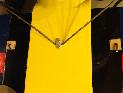 After returning home, 1/16" birch plywood was cut into 3/4" squares and drilled for the Maxlok key diameter. The squares were 30-minute epoxied to the bottom of the lower wing fairings over the Maxlok key holes, which only go through the extremely thin wood on the bottom of the lower wing fairing. The 3/4" square 1/16" birch plywood was painted black. The plane was also checked for horizontal balance and found to be okay. The actual maiden took place on the morning of July 5, when the wind conditions were ideal. The wind was light and varied from just down the runway to slightly quartering. The plane veered sharply left on takeoff. It required a lot of right rudder trim and right aileron trim and down elevator. The CG was set exactly at the recommended two inches behind the leading edge. It flew like it was tail-heavy and was a bit of a handful and not easy to fly. The recommended throws were used on all control surfaces. Denny Sumner helped by moving the trims as I had to totally fly the plane at all times. Just as I set up for landing, Keith Shaw arrived. The landing was good, but it flipped over on its back. The ailerons along with the flaps, rudder and elevator were physically trimmed on the plane and the transmitter controls returned to neutral. Before flight two, 3 ounces of lead was taped to the bottom of the cowl paralleling the fuselage and starting fairly close to the front of the cowl. That moved the CG to approximate 1 3/4" from the leading edge of the top wing. Keith took the plane off with only a slight veer to the left. He only added a couple of clicks of trim to the right for both ailerons and rudder. The elevator still needed quite a bit of down trim. He flew for only a couple of minutes, did a roll, loop, and checked the stall characteristics. Finally he handed me the transmitter. It was an entirely different plane to fly now. It was easy to feel comfortable with. The rest of the flight was simple circuits and then a set up for the landing. Again, the plane flipped on landing. More down trim was physically added before flight three. The flight was relaxing and enjoyable and consisted mostly of cruising around. The setup for the landing was excellent and it rolled along nicely on the grass but flipped over again. The takeaway is that it needs plenty of nose weight and should hang level 1-3/4" from the leading edge of the top wing. The elevator needs a 'dual rate' just for landing to hold the tail down. After returning home, the 4S "A123" 2300mAh pack was changed from a 1x4 configuration to a 2x2 configuration. After sanding away the part of the motor mount that was in the way, two of the cells could then slide into the motor mount. The 3 oz. weight was removed from the cowl bottom and 2.5 ounces of lead stick on weights were formed and epoxied between the ring of the dummy motor and cowl. With two of the "A123" 2300mAh cells moved forward, the 2.5 oz. of lead in the nose of the cowl was sufficient to move the CG to 1-3/4" behind the leading edge of the wing. A thin washer was placed between the left legs of the "+" mount and the motor mount front to provide more right thrust. The rudder was centered. A higher rate was set for the elevator for landing only. Further flights showed that the plane's flight characteristics also benefited from a bit of rudder mixing with the ailerons. On July 9, Keith Shaw did the first flight to check out the changes I'd made. All of the changes were good and no trimming was necessary. My next two flights were familiarization flights. I did a lot of takeoff and landing practice on the third flight. Even with the higher rate on during landing, the plane still wanted to flip onto its nose. I need more practice and maybe even more elevator throw as the last landing was really good; good speed, good attitude, good touch down, but it still flipped on its nose. With 18 flights on the plane, I've found that the best way to land is flip the dual rate elevator to maximum as the plane crosses in front of me on the downwind leg, flip the flap switch to partial flap and flaperons on the base leg and fly it in with a bit of power. That seems to work most of the time now. The plane is fun to fly and pretty much looks like an An-2 in the air. I try to fly it like the An-2s in these YouTube videos at:
The chosen power system is perfect for this type of scale-like flight. Both Greg and I chose motors that are much heavier than the recommended Uranus 35425V2, which only weighs about 150g. Greg didn't have to add any nose weight to balance at 1-3/4" from the leading edge of the top wing. His motor is actually about 60g heavier than mine. If the recommended Uranus outrunner is used, a lot of nose weight will need to be added to balance the plane. Maxford USA Specifications & My Measurements:
With a wing cube loading of about 8, a typical trainer/easy flying sport plane number, and an area loading of 18.4 oz./sq.ft., the plane is relatively easy to fly, but it is definitely not for a beginner! This plane is for an intermediate flyer and builder who wants a plane that looks like an Antonov An-2 in the air, and flies like one. For me, it was both a challenge and learning experience. I hope to incorporate some of the design features into my larger scale version, someday. I can't wait to get out and fly it again. It's a lot of fun. Don't be afraid to give one a try if you want one. Maxford has already taken steps to insure that some of the problem areas are going to be fixed and they are fantastic with customer service. Hits
Misses
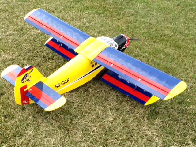 This is Ken Myers' Maxford USA Antonov An-2 Colt ARtF (almost-ready-to-fix). It flies well, but there were some problems during assembly that Maxford USA immediately took care of.
|
To Reach Ken Myers, you can land mail to the address at the top of the page. My E-mail address is: KMyersEFO@theampeer.org