|
Flying High With Electric Power!
The Ampeer ON-LINE!
Fly the Future - Fly Electric! |
|---|
Site Table of Contents
| President: | Vice-President: | Secretary-Treasurer: |
| Ken Myers | Richard Utkan | Rick Sawicki |
| 1911 Bradshaw Ct. | 240 Cabinet | 5089 Ledgewood Ct. W. |
| Commerce Twp., MI 48390 | Milford, MI 48381 | Commerce Twp., MI 48382 |
| (248) 669-8124 | (248) 685-1705 | (2480 685-7056 |
 | ||
| Board of Directors: | Board of Directors: | Ampeer Editor |
| David Stacer | Arthur Deane | Ken Myers |
| 16575 Brooklane Blvd. | 21690 Bedford Dr. | 1911 Bradshaw Ct. |
| Northville, MI 48168 | Northville, MI 48167 | Commerce Twp., MI 48390 |
| (248) 924-2324 | (248) 348-2058 | (248) 669-8124 |
| The Next Meeting: Date: Saturday, September 5 Time: 10 a.m.
Place: Midwest RC Society 7 Mile Rd. Flying Field | ||
| Reminder About EFO Flying Season Meetings Ken shares that EFO Flying meeting dates are tentative. | Power Wire and Power Wire Sizing Ken explains how he selects the power wire gauge for his projects. | |
| NEW - Electric Flyers Flight Box from Retro RC Joe Hass shares information and photos of this new product from Retro RC. | Freewing Pandora Review & Some General RC 'Trainer' Thoughts Ken Myers starts his review of this plane and sharing thoughts in general on RC 'trainer' planes. | |
Dates given for the flying season EFO flying meetings are tentative. The date depends on the weather and may change from the one noted in the monthly Ampeer. The EFO Web site has the most current information posted. Also, emails are sent to EFO members if a date change is required. |
By Ken Myers Preface:
Greg did a very good job with the article, and it contains a lot of useful and accurate information. After reading the article, I sent an email to Jay Smith, the editor of Model Aviation magazine. I told him that I did not appreciate the formatting of the sidebar on page 30 where they chose to use small, medium gray font on a light gray background. It made it very hard to read. Also, there was a statement in that same sidebar regarding amperage that was not true. "So a 3300mAh battery pack is 3.3 amperes." 3300mA is 3.3 amperes. 3300mAh (milliamp hours) is 3.3 Ah (amp hours) and relates to battery capacity. Why battery capacity was included in the definition of amperage is beyond me. The sidebar on page 33 got me to thinking more about wire and connectors. Several days of research lead to the following conclusions.
The wire most frequently used, and recommended, for electric power systems is often just called 'silicone wire'. The wire is a flexible, multi-strand count wire with a silicone jacket insulation. The size, which is known as gauge, of the power wires between the battery and electronic speed control (ESC) is based on the application, the expected maximum current between the battery and ESC and the length of wire from the BATTERY TO THE ESC AND BACK TO THE BATTERY. That is the total length of the positive and negative leads combined. In North America, American Wire Gauge (AWG) is used to identify the wire 'size'. The Internet can be used to convert AWG size to equivalent metric sizes and visa versa. The smaller the gauge number, the larger the wire diameter is. Large gauge (small gauge number) wire can safely handle more current, over longer distances, with less voltage drop than smaller gauge (large gauge number) wire, but it is heavier.Wire, capable of 'handling' the current (amps) without too much voltage drop, also has to be sized for the aircraft. AWG #12 wire is not a good choice for a two ounce plane requiring only a couple of amps. It would be too heavy. A giant scale model requiring 100 amps at full power is not going to use AWG #12 wire. The resistance of the wire will create an unacceptable voltage drop, and depending on the wire's insulation, it might even melt the insulation. Lucien Miller, of Innov8tive Designs, suggests, in a post on RC Groups, that for our purposes, "in RC applications, we can use 100 circular mils per amp or even 75 circular mils per amp..." 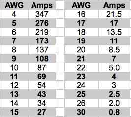 The table is based on a conservative 120 circular mils per amp. The table values are very similar to anecdotal information provided by Bob Aberle in his books on electric flight as well as others. The amps shown in the table are well below what Progressive RC suggests as the amp carrying values of their silicone wire. Progressive RC's amp ratings are about 75 circular mils per amp. Not all AWG gauges are available in multi-strand silicone wire. The connector guide on p. 33 of the article can be used to reference the different types of power connectors used in our hobby. The following list shows the maximum wire gauge a given connector will physically accept. There is no direct relationship between the connector's maximum acceptable wire gauge and the amp rating the manufacturer or supplier specifies for the connector. Smaller wire gauges can be fitted to most connectors. AWG: name of connector
The West Mountain Radio Information on Anderson Powerpoles (APP) including an assembly guide. Going to the actual ACTUAL Anderson Web site reveals that Anderson does NOT call them APP-15A, APP-30A or APP-45A. They call them PP15, PP30 and PP45 They are all rated to 55 amps. PP15 fits AWG 20 -16, PP30 fits AWG 16 - 12, PP45 fits AWG 14 - 10 gauge wire. Most ESC suppliers DO NOT note the wire gauge of the power leads. Some battery suppliers DO note the power lead gauge. Progressive RC has a good selection of connectors and a good video concerning connectors.
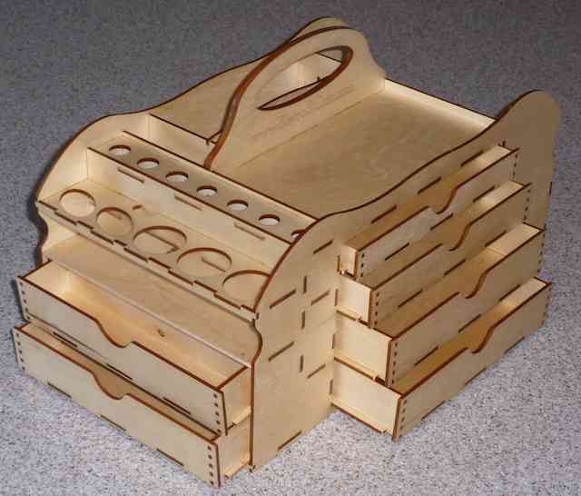
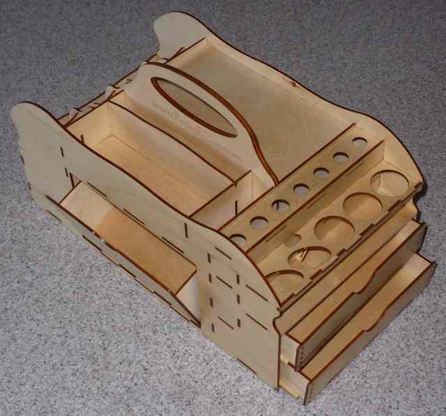
NEW - Electric Flyers Flight Box from Retro RC
There is a new flight box specifically designed for electric flyers. Mark Freeland, of Retro RC, designed the e'Flight Box to solve the problems associated with easily carrying all the necessary supplies, including batteries, to the field or indoor flying site. You build the e'Flight Box from laser cut plywood. Detailed instructions, with pictures, and drawings are included as are the drawer retention magnets and bin hinge material. There is a lot of drawer space, as well as a location for adhesives and kicker. There is even a place to safely hold a #11 knife. The e'Flight Box can be purchased from your local retailer of directly through Retro RC or 248-212-9666. 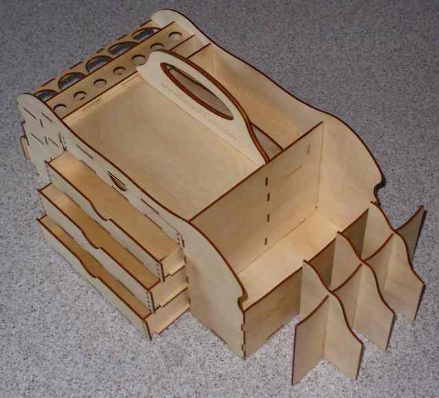
Freewing Pandora Review & Some General RC 'Trainer' Thoughts
Preface:
For the past few years our flying field has had fairly thick and long grass through the spring. Also, the spring winds have, for the most part, been from the south. That means that the wind is blowing across the field from our backs. Taking off into the wind, towards the pits, is unacceptable. Both the Flyzone Sensei and ParkZone T-28, used for flight instruction, have had problems taxiing and taking off. They are both tricycle landing gear planes. The nose wheels on both planes often 'dig' into the thick grass, or they sometimes tip over sideways due to the crosswind getting under their wings. I decided that, for this field and typical wind conditions, I should add a conventional landing gear (tail-dragger) 'trainer' to the mix. I had some basic parameters in mind when I started my search for a conventional landing gear trainer.
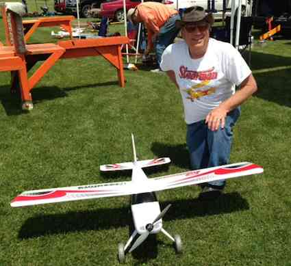
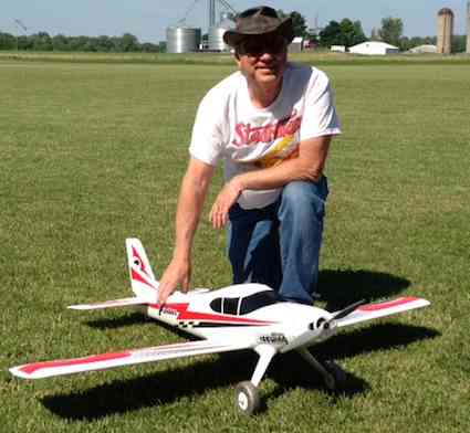
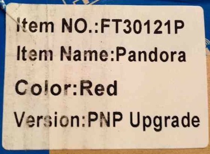
The choices were very limited. The Multiplex Mentor and Freewing Pandora were the only two conventional landing gear trainers, that I found, that met my simple criteria. The ParkZone Sport Cub S and Flyzone Beaver were not considered because they have their batteries loaded from the bottom of the aircraft. The Multiplex Mentor is provided in kit form. That means that there are several pieces, including the fuselage halves, that need to be glued together using medium CA type glue (NOT Foam Safe CA!). Multiplex calls its EPO foam (Expanded Polyolefin foam) ELAPOR®. The motor and electronic speed control (ESC), as well as the power battery, needs to be provided by the builder. All of the onboard radio components, servos, 'receiver' and a recommended receiver battery, if used, need to be provided by the user as well. I almost always select my own motor and ESC to match A123 Systems 2300mAh/2500mAh cells and use a Castle Creations' 50-amp (ICE or EDGE) ESC with a switching Battery Eliminator Circuit (BEC) with all of my 4S or larger A123 packs. A receiver battery would not be necessary. Selecting the appropriate Hitec servos would not be a 'problem' either. (the Ampeer, Dec. 2013) It's a relatively large size for this type of foam trainer with a 65 inch wingspan and 698 sq.in. of wing area. That size makes it easy to 'see' and stay oriented on in the air. With a given ready to fly weight of 71 ounces, or about 4.5 pounds, the wing area loading could be 14.6 oz./sq.ft. and it could have a wing cube loading factor of 6.65 (typical for a park flyer - but it is NOT a park flyer!). Using a 5S 2300mAh/2500mAh pack would likely result in a 5 lb. (80 ounce) ready to fly weight and change the wing loading and WCL factor a little. It would still be a very good 'trainer'. Before my research, I was not familiar with the Freewing Pandora. I found references to it on RC Groups in the Beginner Training Area (Aircraft-Electric) section. It was mentioned in various threads along with the Apprentice, Sensei and Mentor. I noted that Motion RC, of Lake Barrington, IL, sold it. I had become familiar with Motion RC while researching Tactic radio videos. The Freewing Pandora is unique. It can be configured as either a cabin, high-wing style aircraft or low-wing aircraft. Tricycle and conventional landing gear are also configuration options. The Freewing Pandora is an EPO foam, almost ready-to-fly (ARF) plane. It uses only screws for assembly. An outrunner motor and 30-amp ESC are installed and a three-bladed prop (11x6) and spinner are included. A 2200mAh LiPo battery pack is recommended and must be provided by the user. The upgrade red version, there is a blue version as well, that I received, had three 9 gram servos installed (two for the ailerons and one for the elevator) and a 17 gram servo installed for the rudder/tailwheel/nose gear. No data is available on the servo dimensions or torque. Very thin wire pushrods, running in plastic tubes, are also installed. The pushrods have small clevises installed on the flight surface ends. The pushrods are attached to the servos using connectors similar to Dubro E/Z connectors. Only the receiver needs to be provided to complete the onboard radio system. Flaps are optional and need to be cut free of the wing. The control horns, pushrods and clevises are provided for the flap option, but the servos must be purchased separately. The almost useless instruction manual was downloaded from the Motion RC Website. The black and white instruction manual, that came with the plane, was identical and did not show the upgraded rudder/nose wheel/tailwheel servo. Like many of the EPO Chinese planes, the wing area was not noted. The wing span is noted at 55-1/8". (Measured - 54-15/16") The five videos of the aircraft flying, available on the Motion RC Website, show a person with the plane and suggested that the wing area is reasonable. The videos of the Pandora indicated that the wing area loading and WCL factor should be reasonable for a trainer type plane. The videos show it being flown low and slow without the use of the optional flaps. Unboxing - Really? Normally I feel that unboxing videos and notes are a waste of time, but I thought there were some significant things to note. Note: A Pandora unboxing video on YouTube The outside shipping box arrived in fine shape. The shipping box had a label on one end that noted the plane inside as the Upgrade Red version. There was also a sticker on the inside box cover on the front, lower left corner that said "Upgraded Version". The compartmented foam box, with the component parts, looked good, but I noted a rattle when bringing the box in the house. After opening the box, I believe the rattle was the nose gear/wheel pant/wheel assembly banging around in a large cut out section in the foam component box. 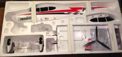
  I searched the Internet for the parts layout in the box. It appeared, from the very poor instruction manual, that the kit was shipped with the nose gear attached and possibly the cabin high-wing center section and bottom fuselage center section filler already attached. The instruction manual also seemed to indicate that the tailwheel assembly needed to be attached, but it was already attached. The fuselage actually came with the low-wing canopy installed on the fuselage and tailwheel assembly attached. After opening and inspecting the box contents, the weights and measures were taken. A triple-beam scientific balance scale was used to weigh the components in grams. The grams were mathematically converted to ounces. The linear measurements were taken using United States customary units and converted to metric units.
(lightest weight - no tail weight included*) Airframe only weight: 46.16 ounces 1308.5 grams
(heaviest weight - no tail weight included*) Airframe only weight: 49.20 ounces 1389.75g
It appeared that the rudder/tailwheel/nose gear servo was changed from the stated 9g servo to an unlabeled Freewing 17g servo. An email was sent to Motion RC asking if they knew of any other upgrades to the upgrade version. I actually received replies from a couple of different people at Motion RC stating they didn't 'believe' anything else was upgraded. My plane is ONLY going to be used in the conventional landing gear configuration. That eliminated any concern about the nose gear mounting plate integrity from banging loads on the nose wheel attachment plate or servo issues. The main conventional landing gear will crack near the small fairing mounting screws.
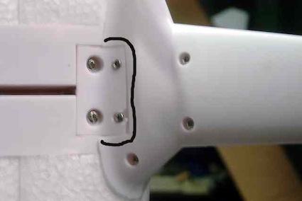 I removed the conventional landing gear fairings. The fairings have three cross-members with semi-circles for the just over 3.5mm (~5/32") landing gear wire to pass through. DAP Kwik Seal Kitchen & Bath Adhesive Caulk was applied down wire center line and along the ribs. More caulk was applied in the top of the fairing where the wire has the most stress where it bends into the fuselage. The fairings were screwed back together and the caulk allowed to 'dry'. The weight of the conventional main gear was now 140.5g. That is an increase of of 27.95g, or about an ounce, more than the supplied landing gear. 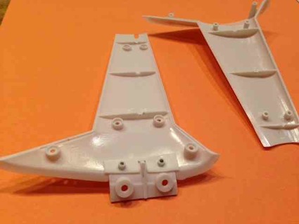 After seven flights I noticed the tailwheel was spinning freely. This was not unexpected. How I tried to fix it is found in this thread on RC Groups. Unfortunately there is really no room in the rear of the fuselage to get a 1.5mm allen wrench on the set screw in the side of the metal top fitting that the steering arm is attached to. I learned that I had NOT gotten it tight enough. Ten flights later, the tailwheel was loose again and partially turning. To find out what was really going on, I completely disassembled the tailwheel assembly. To get inside the fuselage to the tailwheel assembly, I removed the two screws holding the vertical stabilizer/rudder assembly and the horizontal stabilizer/elevator assembly to the airframe and removed the horizontal stabilizer and vertical stabilizer assemblies. I discovered that there are more pieces to the tailwheel assembly than apparent. At the top, inside the rear of the fuselage, is a metal fitting for the steering arm. The cylindrical metal fitting has flats on two sides near the top and a threaded hole, centered in the top of the cylinder, to secure the steering arm with a small screw. There is a 1.5mm threaded hole in the side of the fitting for a set screw. A 2mm diameter by 26mm long 'shaft', with flats on each end, is connected, using 1.5mm set screws, between the top fitting and a cylindrical coupler under the fuselage. From the photo on p. 14, of the poorly written and illustrated manual, it is impossible to tell that the metal 'collar' beneath the fuselage is really a coupler and not just a 'collar' with a set screw in it. Only the 2mm set screw, at the bottom of the coupler, is visible. In fact, the coupler has a 1.5mm threaded hole on one side near the upper end of the cylinder and a 2mm threaded hole, on the same side, near the lower end of the cylinder. The 2mm prebent tailwheel wire, with the tailwheel attached, goes up through the hole in the plastic tailwheel bracket into the lower end of the coupler and is held in place by a 2mm allen screw, as shown on p. 19 of the poor excuse of a manual. I found a piece of approximately 2mm music/piano wire in my 'stock' and cut a new top shaft 31mm long. I ground flats on each end using a grinding wheel in a Dremel. The top fitting was very snuggly tightened onto the new 'shaft' top. A 1/8" long piece on yellow inner Nyrod was cut as a 'bushing' to prevent too much vertical play in the tailwheel assembly. Any piece of round plastic, that the 'shaft' can pass through, would have been fine. The new 'shaft', with the top fitting securely attached, was dropped through the plastic tube 'shaft' guide. The new 'shaft' was fed through the Nyrod bushing and into the top of the coupler. The top fitting and coupler were aligned and the 1.5mm set screw, in the coupler, was tightened onto the new shaft. The lower tailwheel wire, with the tailwheel on it, was positioned up through the bottom of the tailwheel bracket and into the coupler. The 2mm set screw, in the coupler, was tightened onto the tailwheel wire. 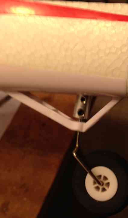 The steering arm was screwed back onto the top fitting and the tailwheel pushrod attached to it. The horizontal stabilizer/elevator assembly and vertical stabilizer assembly were screwed back into place and the pushrods attached and adjusted. The requirement of a 1.5mm allen-type ball driver was not noted in the very poorly written instructions. There are actually four 1.5mm set screws used for the plane and only one 2mm set screw. Only a 2mm allen type wrench is provided. Having a metric Bondhus Balldriver L-Wrench Set on hand is always a good idea when dealing with Chinese planes. IMPORTANT NOTE: If the plane is to be configured using the conventional landing gear, I HIGHLY RECOMMEND the previously noted tailwheel modification as the first step of assembly of this plane. I never trust the supplier recommended center of gravity (CG), never! I always recalculate the CG. Since this is a very simple rectangular wing planform, the center of gravity was calculated using an online CG calculator. The online calculator outputs, using 15% and 20% static margins, were identical to the recommended CG in the really poor instruction manual. The recommended CG is 70mm (~2-3/4") to 80mm (~3-1/8") from the leading edge of the wing. There are some slots in the bottom of the wing panels that can aid in checking the CG. Using the cabin top wing option, it is easy to set up the CG, even if the low-wing version is to be used. The CG is relatively the same on both versions, as the wing placement aligns top and bottom. 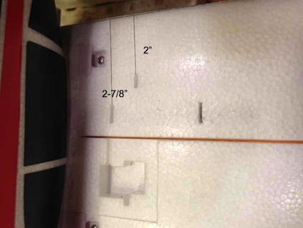 The photo shows the slots. The forward slot is 2" from the wing panel's leading edge and is 3/8" long. The rear slot is 2-7/8" (73.025mm) from the wing panel's leading edge and is 1/2" long. These make good reference points for checking the CG. While double-checking the CG information, I realized that I had my initial CG too far forward on the first seven flights. My CG was at 2-5/32" or about 55mm from the leading edge. That is about the middle of the slot 2" from the leading edge of the wing panel. There was no problem flying the plane with the CG placed at 55mm. No excessive up elevator was required for level flight and there was plenty of elevator for landings. The plane's overall handling characteristics were very gentle. I decided to adjust the CG to that recommended by the supplier. I was not surprised that tail weight was required. 1.25 ounces of Great Planes Self Adhesive Lead Weights was painters' taped to the bottom of the fuselage, just ahead of the tailwheel bracket to achieve the recommended balance of about 2-7/8". From my research, it appears that tail weight WILL be needed on all versions of this plane to achieve the recommended balance. The diagram of the plane assembly, located at the end of the poorly written and illustrated instruction manual, page 18, shows the screw positions and calls them out by name. The diagram is really all that is needed to assemble the aircraft. The Chinese naming of some parts in the parts bag and quantity accuracy leaves a lot to be desired! Here is my translation, along with their uses. They are listed by total quantity, the Chinese designation in the illustration, the description and where it is used. Don't be surprised if some screws are missing and the quantities differ. 4 ea. PM3*25mm, pan head machine screw, two hold on either wing center section and two are used to affix the bottom fuselage center section when the high-wing configuration is used 2 ea. PA3*10mm, pan head philips self-tapping screw, used to hold the tail assembly together 4 ea. PWM3*6mm, pan washer head machine screw, holds the wing panels to the center section (mislabeled PM3*6mm on diagram) 4 ea. PA3*18mm, pan head philips self-tapping screw, used to affix the trike gear main landing gear 4 ea. PWA3*18mm, pan washer head philips self-tapping screw, shown to hold conventional gear in place in diagram - NONE WERE PROVIDED WITH MY PANDORA - PA3*18mm were used 4 ea. PWA3*8mm, pan washer head self-tapping screw, holds "Nose Gear Fixing Part" in place 3 ea. PA2.6*10mm, pan head philips self-tapping screw, attach the spinner to the spinner backplate 6 ea. PT1.7*14mm, thread forming screw for plastics, control horn screws, four are used for the optional flap control horns and there appears to be 2 extra A metric ruler is handy for sorting the screws. Other parts notes:
The servo surface arm and servo surface spacer are the two nylon parts for the optional flap control horns. The Main wing servo metal wires are the pushrods for the optional flaps. There were four pushrod clevises. Two are for the optional flap pushrods and there were two extra in this kit. These seem to be what the Chinese are calling Chuck (1.2mm). The parts bag notes 2 pieces, but there were four. My knock on the manual is really inconsequential, as the plane can be easily assembled, by someone with some experience, just using the parts illustration. It is NOT a plane for a 'rank' beginner with no experience assembling RC aircraft and no flight experience. For the experienced RC model assembler and flyer, this is an enjoyable plane. It flies quite well. Keith Shaw has flown both the high-wing and low-wing, taildragger versions, and noted that for a 'convertible' plane, it flies better than most he's had a chance to fly. It is also working well as a trainer with an instructor and buddy box system. If the uniqueness and value appeals to you, I'd recommend it. The stock power system, using a 3S LiPo battery, is very adequate at about 100 watt in per pound of aircraft weight. The more adventurous might enjoy using a 4S LiPo battery with the stock motor and prop. That requires at least a different ESC. A 50-amp ESC, with switching BEC, should be adequate, as the expected amp draw should be about 38 or 39 amps with the stock motor and stock 3-blade 11x6 prop. Whether the 120g stock motor can handle that amp draw is questionable, but other brand motors, which I will discuss, will fit. More on the stock and optional power systems appears in Part 2. I actually received an email from Motion RC on June 2, 2015 that said in part, "... if you find it sluggish, I use a 4S LiPo in it and it really makes it a better flying plane. The ESC and motor can handle the extra draw just fine." Unfortunately, the email was only signed, "Your Motion RC Team". I'm not so sure about the ESC, that is why I'm recommending at least an ESC change when going to a 4S LiPo battery and sticking with the stock motor and stock prop. A word of Warning: If this plane sounds interesting, and you want to add one to your fleet, I'd order it soon. Almost every time that I've reviewed a plane, it becomes 'unavailable' or discontinued! To Reach Ken Myers, you can land mail to the address at the top of the page. My E-mail address is: KMyersEFO@theampeer.org |