|
Flying High With Electric Power!
The Ampeer ON-LINE!
Fly the Future - Fly Electric! |
|---|
Site Table of Contents
| President: | Vice-President: | Secretary-Treasurer: |
| Ken Myers | Richard Utkan | Rick Sawicki |
| 1911 Bradshaw Ct. | 240 Cabinet | 5089 Ledgewood Ct. W. |
| Commerce Twp., MI 48390 | Milford, MI 48381 | Commerce Twp., MI 48382 |
| (248) 669-8124 | (248) 685-1705 | (2480 685-7056 |
 | ||
| Board of Directors: | Board of Directors: | Ampeer Editor |
| David Stacer | Arthur Deane | Ken Myers |
| 16575 Brooklane Blvd. | 21690 Bedford Dr. | 1911 Bradshaw Ct. |
| Northville, MI 48168 | Northville, MI 48167 | Commerce Twp., MI 48390 |
| (248) 924-2324 | (248) 348-2058 | (248) 669-8124 |
| EFO Flying Meeting: Saturday, September 1 Time: 10 a.m.
Place: Midwest RC Society 7 Mile Rd. flying field Everyone with an interest is WELCOME Proof of AMA membership required to fly | ||
| The June EFO Flying Meeting Combined with the Midwest Fly 4 Fun A Midwest & EFO Fun Fly Report | Flite Test Partners With amain hobbies New information regarding the Flite Test Store |
| The August EFO Flying Meeting A report on the August Flying Meeting | Electric Radio Intercept Free Flight Bob Kopski describes what it is and shares some examples. |
| Servo Arms, Movable Surface Control Horns, and Movable Surface Control Throws Ken discusses these essential items. | |
"The Sunday, June 24 EFO flying meeting was held in conjunction with the Midwest RC Society Fun Fly Event. The weather, while not perfect, was quite flyable. There was an overcast for most of the day. It started off a bit chilly. The wind was pretty much out of the west, so a take off from right to left was possible at the Midwest flying field. Thanks to Pete Waters, the organizer of the Midwest Event the coffee and donuts, for a small donation, warmed things up a bit. The Fun Fly included Midwest RC Society members, as well as EFO members. The events came off smoothly and were a lot of fun. After the flying events were over, several more members, of both clubs, joined in the flying and just having a good time among friends. Pete Waters wrote up a nice article describing the event. It was published in the August 2018 Midwest RC Society newsletter, the Monitor. Sunday, June 24 Via Email from Peter Waters The beginning session for this program was delayed through typical weather, but it finally happened on Sunday, June 24. The first event was a climb and glide. The motor was run for 7 seconds and then shut down. The person with the longest glide time was won the event. The glide was to a spot landing.  Denny Sumner managed 124.26 seconds using a modified Sig Four Star 40. During this event, it was possible to get triple the score if you glided inverted! Even though the gathering throng of spectators encourage the pilots to do the inverted glide (is that heckled?), no one chose to do so. The second task was a "Virtual Limbo". Two poles, one on each side of the flying field, were used as gates, but there was no string, ribbon or pole across field. The "judges" decided "Yes or No" as to whether the plane passed under the tops of the poles. The contestant had one minuted to get as many passes in as possible. Dangerous Dennis and Rough Rider Roger scored 4 passes each. The third task was "Dunk the Can". An empty beer can was tied on a long string to the model. The contestants were allowed three passes to "dunk" the can on the snow board target. 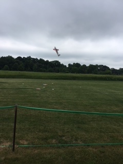 The closest was Larry Markey using his giant model to tail hover - close but no prize. Ken Myers, flying his SuperEZ trainer, also managed to dunk the can just before the target twice and drag it across the target. That didn't count either! Each flight ended with a spot landing, aiming at a towel. The closest through the program was Larry Markey. He won the ONLY prize, a turned wooden bowl. It was a fun filled few hours, and will be repeated monthly for the two clubs. 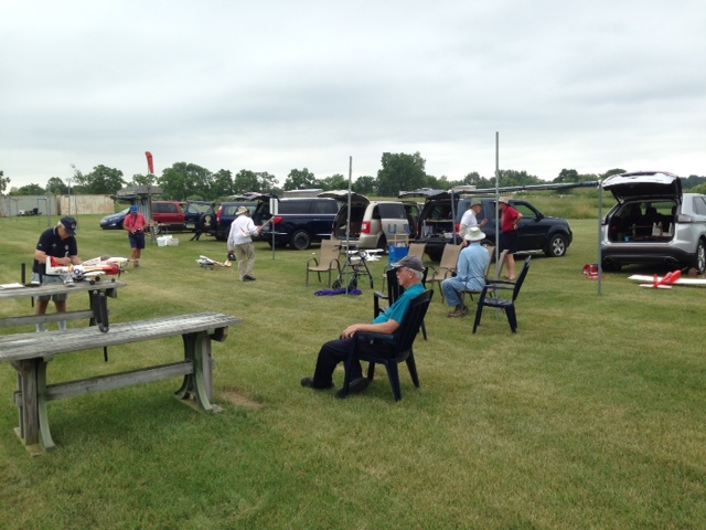 Thank you to the sideline spectators and helpers.
 By Ken Myers "On July 20, 2018 the Flite Test online store was updated. All of a sudden hundreds, possibly thousands, of more items were available through the FT online store. Brands such as Great Planes, which no longer exits, showed up in many categories. Tactic radios were available. The FT online store search became much, much harder to use and quite a bit more frustrating. I could no longer find many of the Flite Test branded items such as landing gear wire, pushrods and their own brand of E/Z links. At first I thought that there was some kind of connection between Flite Test and Horizon Hobby, mostly because of the FT Radian from Horizon Hobby and the fact that Horizon Hobby recently purchased Hobbico, including the Great Planes brand. I tried to find any possible link between the two, and couldn't find it. I thought that maybe the proposed hobby store at Edgewater Air Park might be a Hobby Town store, because the identical items at Hobby Town and the FT store had the same descriptions and reviews. I could find no link between Hobby Town and Flite Test. On August 5, 2018 I found a video that explained that the connection for both Flite Test and Hobby Town is through amain hobbies. The Flite Test video, explaining the amain hobby connection, was posted to YouTube on July 26. The amain hobbies connection is why when you open the following three pages for amain hobbies, Flite Test and Hobby Town, you see the same reviews. It appears that all of the data is coming from the same place, amain, although the pages are customized for each "store". www.amainhobbies.com/flite-test-simple-cub-electric-airplane-kit-956mm-flt-1053/p675949 store.flitetest.com/flite-test-simple-cub-electric-airplane-kit-956mm-flt-1053/p675949 www.hobbytown.com/simple-cub-electric-airplane-kit-956mm-by-flite-test-flt-1053/p675949 Only the domain name is different in the URL. On August 6, amain hobbies posted a video to YouTube titled "New Flite Test Store Navigation Tips & Tricks Ep. 2". I did not find the video all that helpful. The August EFO Flying Meeting
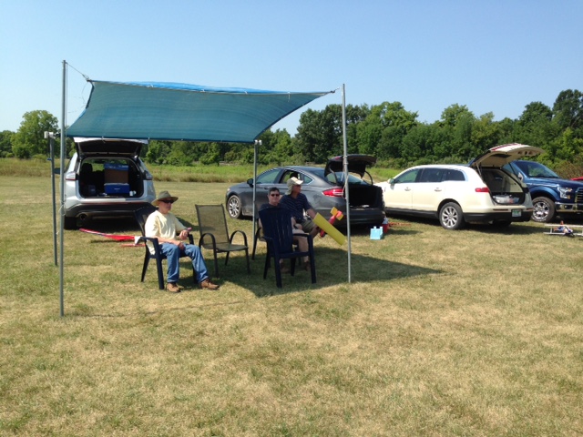
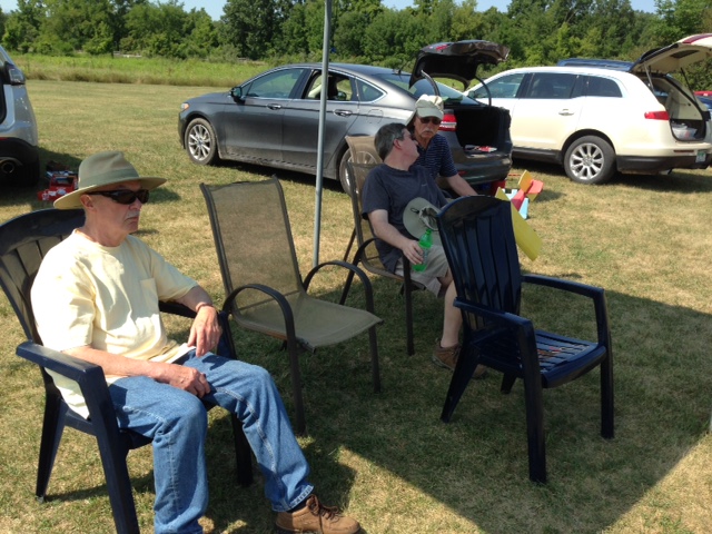
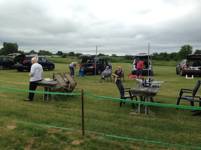
As seen in the photo, Saturday, August 4 was a beautiful, if extremely hot, flying day at the Midwest RC Society 7 Mile Rd. Flying field in Salem Township, MI. The winds were light and variable, but not a bother at all, even when working with Mike Russell with his new, modified, Flite Test Simple Cub.
Mike Russell, Dave Stacer and EFO vice-president, Richard Utkan seek shade under one of the shelters along the flight line. Rick Sawicki had out several of the planes that he had not flown recently. One of them presented a problem. He took the plane up for its first flight in a long time and there was a sound, like a barking dog, coming from the plane. At first he thought that the E-Flite ESC was losing timing. After discussion among the group, he decided to use a different battery. The different battery did not produce the barking noise. He was going to check out that first pack he used and see if he could find a problem with it. 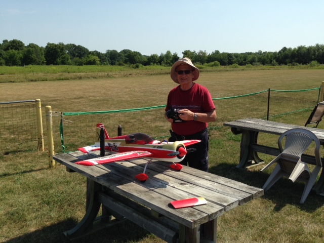 The photo shows Rick and his barking plane.  The photo shows more of Rick's oldies but goodies as Denny gives Greg a hand unloading. Ken, as well as working with Mike on updating his flying skills, also flew two more flights on his version 4 modified Flite Test Cub. Ken was checking the average amp draw of the power system using a Revolectrix 3S 1000mAh pack. Ken�s timer is set up to use the throttle of his Tactic TTX650 radio when the throttle is on. He did a power on 7 minute 16 second flight and a power on 7 minute 6 second flight for a total of 14 minutes and 22 seconds or 0.239 hours on the same battery charge. Later that evening, the battery was recharged at home and 753mAh was returned to the pack. 753mAh is 0.753Ah.
Both flights had consisted of circuits, a few loops, stall turns, many touch and goes and a lot of time doing horizontal 8s. This is very consistent with several other average amp draw tests that Ken has performed on this power system in the Simple Cub. He actually calls it his "amp sipping" plane. Just a random thought thrown in here: Why on earth are so many folks building the FT Simple Cub trying to stuff a 3S 2200mAh pack into it? Flite Test is now recommending a 3S 1000mAh - 3S 1300mAh. That seems about right to me. Electric Radio Intercept Free Flight
Many of you may remember Bob as the very long running electric columnist in Model Aviation Magazine. He has also contributed several articles that were published here in the Ampeer. KM Hi Ken, I've been toying with a new-to-me Electric variant that I'm sharing with you. You are free to share it with Ampeer readers if you think any might have an interest. I got the idea on-line from "domoremath" wherein that fellow details MANY of his rubber powered planes flying in a high rise bounded park in Manhattan. There are over 60 videos on that site and the guy is an amazing builder of classic rubber models - now with RC added in. 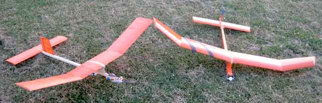 One photo shows two Electric Radio Intercept free flights. One called "RECALL" is my 45", 8 oz original, the other is a kit derived QUARK by KRC President Denny Carlson. The idea with both is to fly some good 'ole free flight on a too-small field relying on rudder only RC intercept to avoid the hostile field boundaries ' like trees 'n stuff. The idea is "climb then glide" - safely. We are calling this R/I instead of R/C. 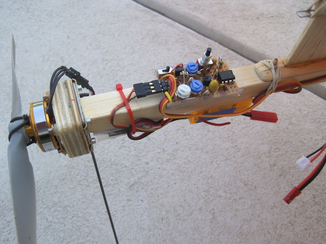 One RECALL photo shows a home-brew electronic assembly. I call it a Motor Management Circuit. It allows screw adjusted motor RPM and motor run time over the range of 10 to 90 seconds. The QUARK employs a commercially available equivalent. Both planes have brushless motors and ESC's and 2 cell LiPo packs. 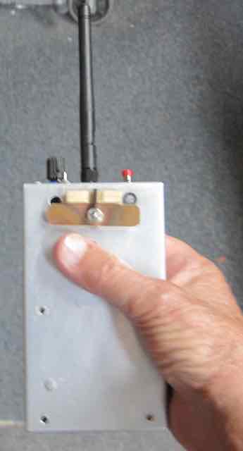 I'm using a homemade Spektrum compatible transmitter with a finger operated "left-neutral-right" rocker switch for "bang-bang" rudder servo operation while Denny uses a conventional Tx. An interesting field experience has been that of randomly handing my Tx "cold turkey" to fellow club members - thirteen in all so far - with NO problems from take off thru landing! "Ground school" just shows "how to" switch operation - and off they go. Most found particular fun in attempting to hit our runway - in the glide - with only the limited rudder operation. Not so easy - and several just wanted to keep trying flight after flight - now experiencing what RCers of the early days of escapements did some 60 years ago. Hey - it's just another fun Electric variant - and when my piloting is not the best and I miss the runway (the good glide is a fooler!) I get much needed exercise going after RECALL! And YES, I continue enjoying Ampeer very much - Thank You! Warm Regards,
Servo Arms, Movable Surface Control Horns, and Movable Surface Control Throws
When I started using proportional radios, the first one I purchased was a Cox 2-channel (made by Sanwa). The set included two rotational-type servos, like we mostly use today. There were still linear servos available for some high end systems of the time. Rotational servos became the standard used in RC model aircraft. Protruding through the top of the servo case is an axle. A flat lever, with spaced holes in it, is attached to the axle. The lever uses the rotational movement, within a certain defined degree of rotation, to provide a linear movement, via a pushrod of some type or cables, to a control horn on a moveable surface or steering arm. For more than 1/2 a century I called the lever part of the servo a servo arm. I wasn't entirely wrong. Spektrum RC lists "Servo Arms (2) for SPMSA22".
Spektrum only lists two of these types of items as servo arms, and all of the rest of them are call servo horns. Check it out on their Web site. Hitec only uses the term servo horn. I recently started writing an article regarding control throws and setting up planes for their initial flight. I started doing some CAD drawings showing the linear movement of the pushrod compared to degrees of movement of the lever/servo arm/servo horn. I know that all servo horns are not created equal for a lot of different reasons. What I didn't know was that my assumption that four armed servo horns were symmetrical was wrong! I never asked myself the basic question, "Why four arms on a servo horn?" I remembered seeing drawings of servo horns in the past that gave dimensions. I couldn't remember where I'd seen them. I turned to Google and searched, and searched, and searched and searched and searched. Arms, horns, it made no difference. I could not find what I was looking for. I thought maybe I'd seen them on the Servo City Web site. I struck out again. Finally, after looking at images in the Google search, I found a reference to the Hitec servo horns in 2011. The reference is in .pdf format from Hitec. I finally got the dimensions that I was looking for, at least for Hitec servos. Servo horn dimensions are not listed on the Hitec RCD Web site. There are photos of the servo horns and a table that indicates what servo horn fits on what servo, but there are no dimensions. The four arm servo horns dimensions were not what I had expected. I have drawn a lot of servos into my 2D CAD program to use when designing planes. When drawing the servo horns, I just drew one arm of a four arm servo horn and copied it to the other three positions. WRONG!
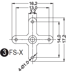
The dimensions shown for the Hitec servo horns show that NOT all four arms are the same. If they were, what would be the point? The measurements are presented in millimeters (mm). One set of holes, closest to the servo screw, on the FS-X arm is 6.5mm from the center hole, and the other is 7mm from the center of the center hole. In his article titled "Servo rotation versus linear motor", Fly RC Feb. 21, 2013, Jack Sallade states, "Most servos "out of the box" are made to rotate to a maximum of around 60 degrees in each direction or 120 degrees overall."
A Hitec FS-X servo horn was provided with the Hitec HS-53 Super-Economy Feather, Nylon Gear Servo (Part No:�31053S) that I've been using in my RUA 2-4-10 and modified Flite Test Simple Cub. I determined that both subjectively and mathematically, that out of the box, and paired with my Tactic receiver and transmitter, the throw is 45 degrees each way from center. Using 6.5mm hole position, the linear movement between 0 degrees and 45 degrees is 0.18095 inches. Using 7mm, the linear movement between 0 degrees and 45 degrees 0.19487 inches. That is only a difference of 0.01392 inches. That is not really significant at all! When a pushrod is attached to a control horn on a movable surface, with the control horn's hole aligned with the hinge line and 1/2" above the moveable surface, there is only 1 degree of deflection difference on the moveable surface between the two servo horn holes' distances. Using a hole in the surface mounted control horn 1/4" from the moveable surface results in a 5 degree difference between the two different hole spacings in the servo horn. Why this is a 4 arm servo horn is not clear to me. 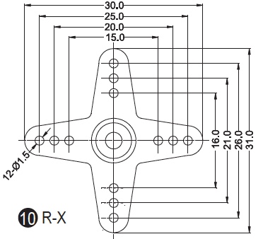 The Hitec Regular R-X horn also only has a 1/2mm difference between the inner most holes and the servo screw. I still have no idea why they do this, since the innermost servo horn hole, closest to the servo screw, is the most significant hole in the servo horn for flying sport and trainer planes that fly on the wing. This part of the article is targeted for RC plane beginner's or low-time RC pilots. Today's computer style radios allow several ways to adjust the control throws in the transmitter, and even provide for different control throws via a switch. The following information provides the 'old school' means of adjusting the surface control throws to a range around 15 degrees, which is adequate in most beginner and sport planes. Originally, Flite Test called for 12 degrees of throw on all of the moveable surfaces for their Simple Cub. This is still noted on the DIY Plans for the Simple Cub in the specifications section. When they updated their Store Web page for the Simple Cub it was changed to "12 - 16 degrees". It is unclear if this means 12 to 16 degrees or 12 degrees Low rate and 16 degrees High rate. The plywood control horns on the DIY plans, and provided in the kit, have the outermost hole of the control horn approximately 1/2 above the movable surface. In the Simple Cub build video, Josh notes that the servo end pushrods go into the innermost servo arm hole, the hole closest to the servo arm screw. He also notes that the elevator and rudder control horn ends go into the outermost hole of the control horns.
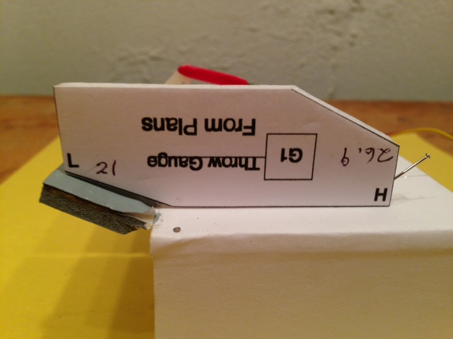
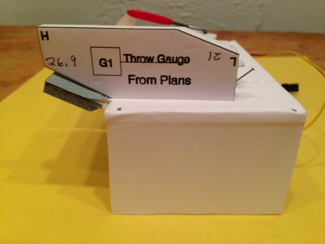
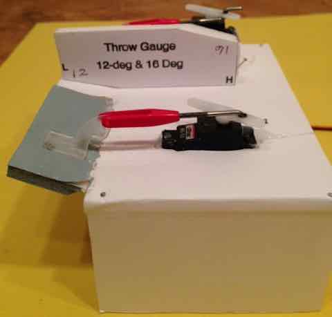
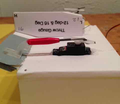
There is a throw gauge provided on the DIY plans and in the laser cut it. Josh is shown using the throw gauge when he talks about setting up dual rates. 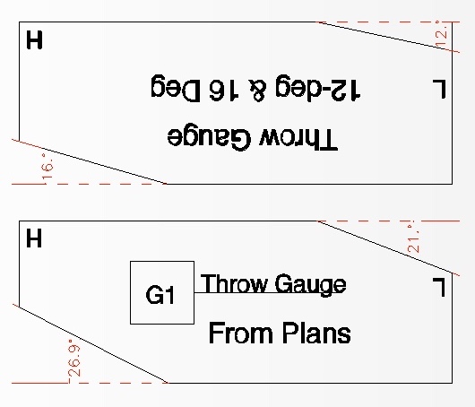 The provided throw gauge has one angle on it that is approximately 21 degrees for the low rate (L) and another angle on it that is almost 27 degrees for high rate (H). Those angles do not agree with the stated throw of 12 - 16 degrees recommended. The angles on the included throw gauge provide too much throw for this type of aircraft and lead to over controlling the plane. A pdf file, printable version, of the two gauges can be downloaded from here. The undesired results of having too much throw can be seen in many of the YouTube videos of the Simple Cub. This video demonstrates the problem of having too much throw. I created another throw gauge with one angle at 12 degrees and the other angle at 16 degrees. (Shown in the diagram with the FT gauge above.) 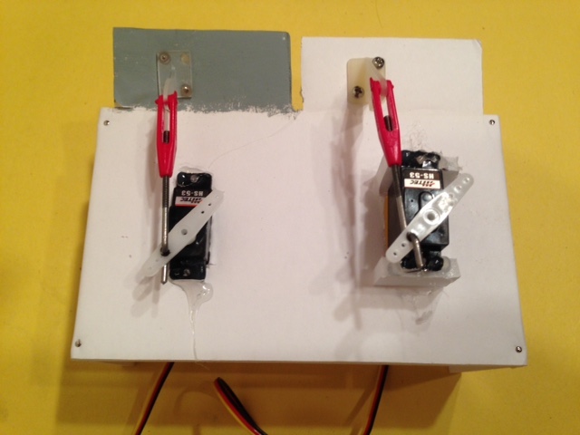 I made a fixture where I could measure two movable surfaces side by side. The fixture contained two identical Hitec HS-53 servos. A control horn was attached to one moveable surface (painted gray) that had its outmost hole about 1/2" above the top surface of the moveable surface. It represented the FT control horn. A second control horn, the Great Planes Large, was attached to the other movable surface. Its outmost hole is approximately 1" above the top surface of the moveable surface. The servo, connected to the GP control horn, was raised so that the angle going from the servo arm connection to the control horn connection had approximately the same angle as the other servo arm connection to control horn connection. Each servo was independently moved to the 'full up' position and left there for measuring purposes. It can be seen that the servo arms are paralleling each other. 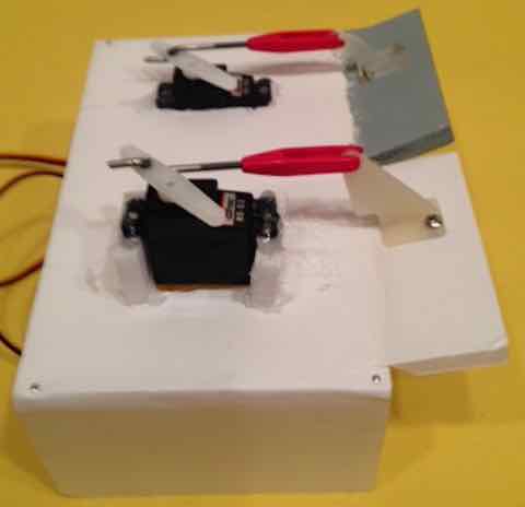 The photo shows the surface with control horn representing the FT control horn, on the painted gray moveable surface, at a greater angle, more deflection, than the one with the GP Large control horn.
The FT gauge shows that it is greater than 21 degrees and a bit less than 27 degrees.
My gauge shows about 12 degrees for the outermost control horn hole (~1" above the moveable surface's top surface) and about 16 degrees when place and adjusted in the second to outmost hole (~3/4" from the moveable surface's top surface). I originally used 12 degrees on the rudder, elevator and ailerons. The 3-ch Version 4 uses 12 degrees on the rudder and 16 degrees on the elevator. The 16 degrees of elevator movement is one of three modifications I made to help keep the plane from nosing in and then nosing over when landing grass. The first time the nosing in and over is shown during a YouTube video of the first landing on grass of the prototype known as the Tubby Cubby. Watch the short segment several times. You will see that the Tubby Cubby noses in, catches its landing gear and flips. Several YouTube videos show the Simple Cub, with landing gear, landing on pavement and not flipping, but I could find no videos of it landing on grass and not flipping. Even landing on a paved surface did not guarantee that the plane wouldn't flip on landing. This video segment is from the end of the build video and shows it landing on pavement. I showed the mechanical method for setting up the throws because the large control horns can be easily purchased to replace the provided plywood control horns and they provide the stated, and correct, throw for this plane. As previously stated, a person familiar with their computer radio COULD change the throws by adjustments in the transmitter. It is my belief that most beginners are not that familiar with their new computer style transmitter and that this would be difficult for them. The technique of using the Large GP control horns to control the throw was used on my modified Simple Cub, RUA-2-4-10 trainer and FMS Super EZ trainer. 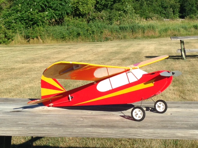
Ken's highly modified Flite Test Simple Cub To Reach Ken Myers, you can land mail to the address at the top of the page. My E-mail address is: KMyersEFO@theampeer.org |