Selecting a first track layout attempt, as I previously stated in the "What I've Learned So Far, section, #22", was EXTREMELY DIFFICULT! There were many variables involved and it took a LONG time to consider all of the possible variables. I found that that process can become overwhelming and even debilitating, which can stop the process in its tracks. Reaching a decision, and actually getting started proved very daunting to ME. I archived the process I went through before deciding on this version of a track plan. That process was long and involved and can be found here. My YouTube video, "My First HO Train Layout in a Long, Long Time - Part 1: The Search for a Track Plan & Layout" also covers the information about my selection of my track plan for my layout. The track plan layout is a fantasy, non-prototypical, switching, or shunting, puzzle type design with a bit of a difference. Many of the switching, or shunting, type layouts are of the shelf-type design. The layout also features two loops and a dogbone for the continuous running of trains, as well as a fairly long passing siding and two reversing loops, which are used to change the direction of a train's travel. There are several sidings that can be used for shunting various rolling stock around the layout. The track design, as well as the goals, considerations and acceptable constraints, noted below, took many months to develop. After studying many track plans, and discarding them after careful study, the track plan layout slowly evolved. The version of the track plan, shown here, is the 14th revision of this track plan. The current version of the track plan is now at revision 18.
To accommodate the two reverse loops, the track plan was designed to fit in a 12' x 4' space. It is quite difficult to distinguish between the three categories, but I've tried my best to do so. Goals
Considerations
Acceptable Constraints
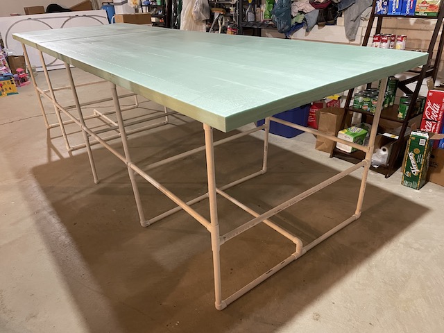
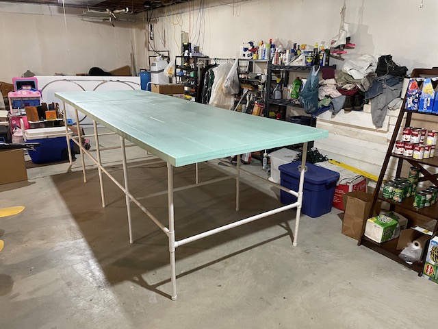
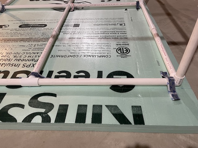
The table top was created using two nominally 4'x8' sheets of Kingspan Insulation R-10, 2-in x 4-ft x 8-ft Unfaced Polystyrene Board Insulation from Lowes, with one sheet cut in half. (I do not recommend this brand for this use. Alternate brands of 2" foam insulation board should work fine.) The frame was made from 3/4" PVC pipe. The table top uses Velcro™ to attach it to the PVC pipe frame. 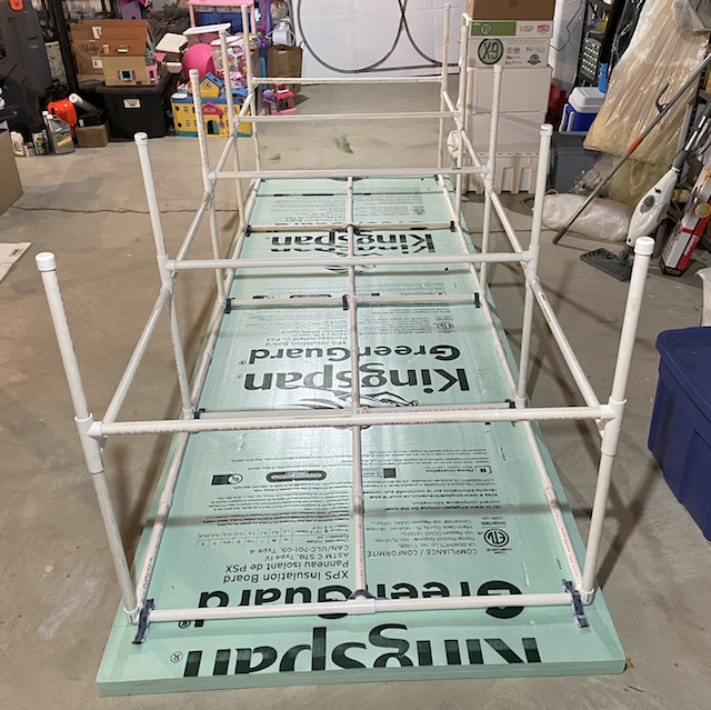
The table top and frame uses Velcro™ to hold them together. Note in the final version photo, the legs were changed to provide a more stable table.
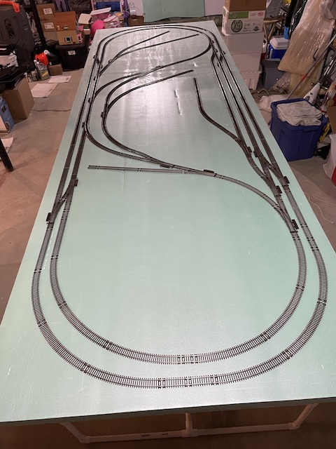
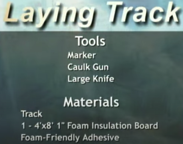
Using the track plan as a guide, the Atlas Code 83 sectional track was laid out on the table top.
There is a YouTube Video titled "My First HO Train Layout in a Long, Long Time - Part 2: How the Benchwork Was Created" that also covers and extends this information. As I began my search for a track plan to be used as my first HO train layout in a long, long time, over fifty years, I only had a few general goals and considerations in my mind. I didn't want it too large so that it could be up and running in a fairly short amount of time. It also had to be free standing, as opposed to near a wall or walls because of the way that things are stored in the basement. Scenery was secondary to ME. Running and operating trains was more important to me to maintain my interest in the model railroad. I really liked the way that trains could be easily reversed and operated on the demo portable layout. I built that layout to explore the use of Dead Rail/Battery on Board using a LocoFi™ sound and controller decoder installed in the locomotive. Unfortunately, there was no room on the demo layout table top, as built, to place more sidings on it. Therefore, a new track plan and layout was considered.
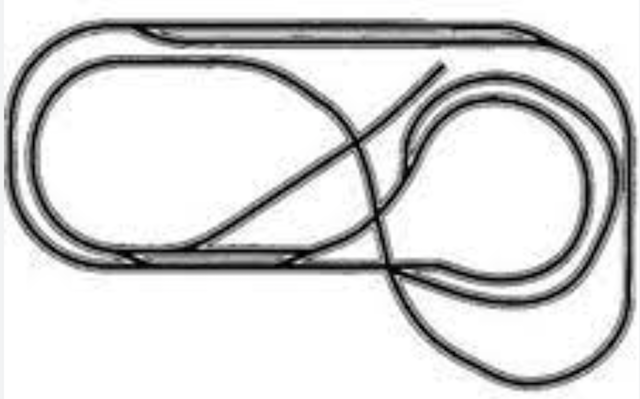
After a lot of searching for a first layout design, I thought that the Atlas HO-12, might be what I was looking for. It is a "folded dogbone" with two reversing loops. Using two reversing loops adds a lot of flexibility to the routes that a train can travel. With the use of Dead Rail/Battery on Board, the train(s) can be run continuously without having to "worry about switching the electrical track polarity". Reversing loops can be accomplished using DC or DCC power to the tracks and even automated, but with Dead Rail/Battery on Board, track polarity change does not have to be taken into account. Dead Rail/Battery on Board makes things much, much simpler. DC wiring for a reverse loop
 I created an X-Track CAD version of the Atlas HO-12 layout and spent hours running and operating trains on the layout. Yes, trains can be "run" on a layout in X-Track CAD. It ran exactly as I wanted it to, but... Without extending the left 4x6, the grade was too steep on the inside left loop heading back to the bridges. I created other iterations that used 4x8 spaces on the left and right, but I was still not satisfied. I added several sidings to increase the operational possibilities. I still was not satisfied. I viewed, and reviewed, a video of an extended version of the Atlas HO-12 track plan on YouTube. This was not going to work for ME, so I continued my research.
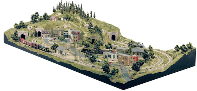
Next I started to look at and study the Woodland Scenics' Grand Valley™ track plan and kit. I carefully watched almost all of the YouTube Videos that I could find using the search term "Woodland Scenics Grand Valley layout". Since the kit had been around for a long time, there were a lot of videos. The various videos demonstrated the construction process, as well as problems with the design and operations of this layout. I thought that this layout would be great to build to learn all kinds of scenic techniques. While researching this design, I purchased the Woodland Scenics' book The Complete Guide to Model Scenery. Unfortunately, I physically cannot read it because of my vision. The Web page does not note the physical size of the book. The pages are 5.5" wide and 8.5" high. It is crammed with a lot of useful information. I was able, with the help of a magnifying glass, to read the chapter titled "SubTerrain". For ME, some of the fonts are too small and some are too light. For a person with excellent vision, this could be a very useful book. I created four different track plans in X-Track CAD for use with the Grand Valley layout. 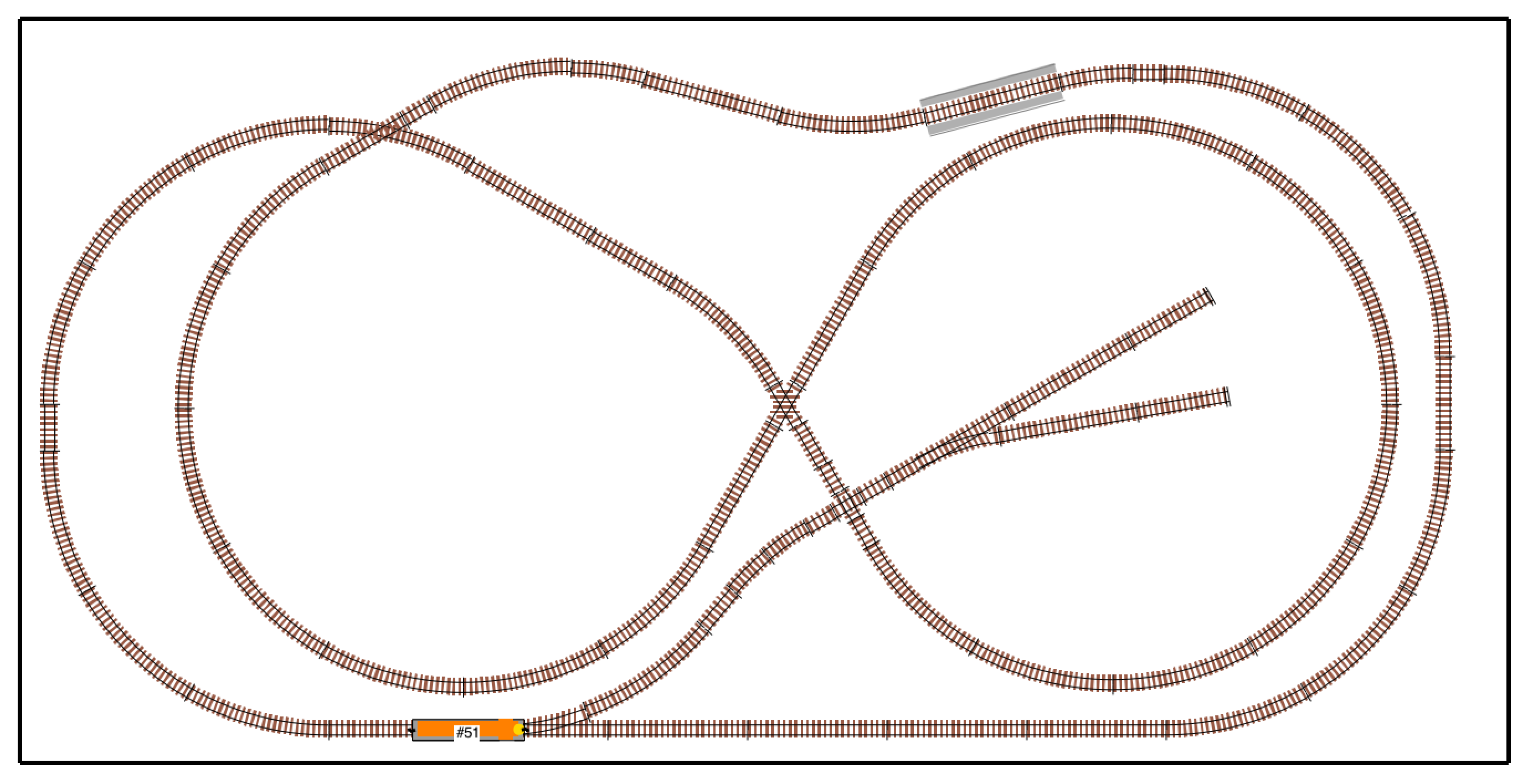 Grand Valley #1 clearly showed the limited operations that could be performed on the layout, but it had over 38' of mainline track wound onto a 4x8 space. 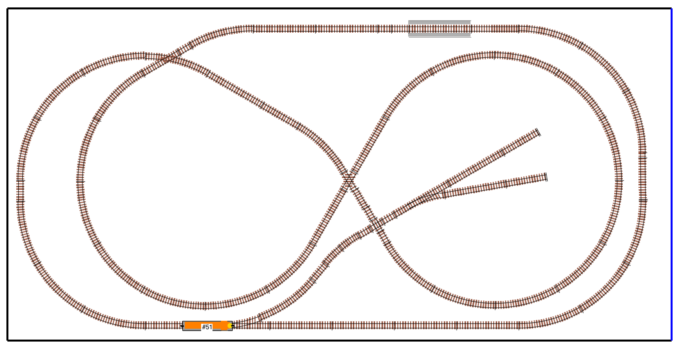 In X-Track CAD, I removed the rear curve, where the bridge was located, and changed it to a straight section because one of the problems noted in the videos was that some parts of some engines, when coming out of the tunnel, would run into the bridge. 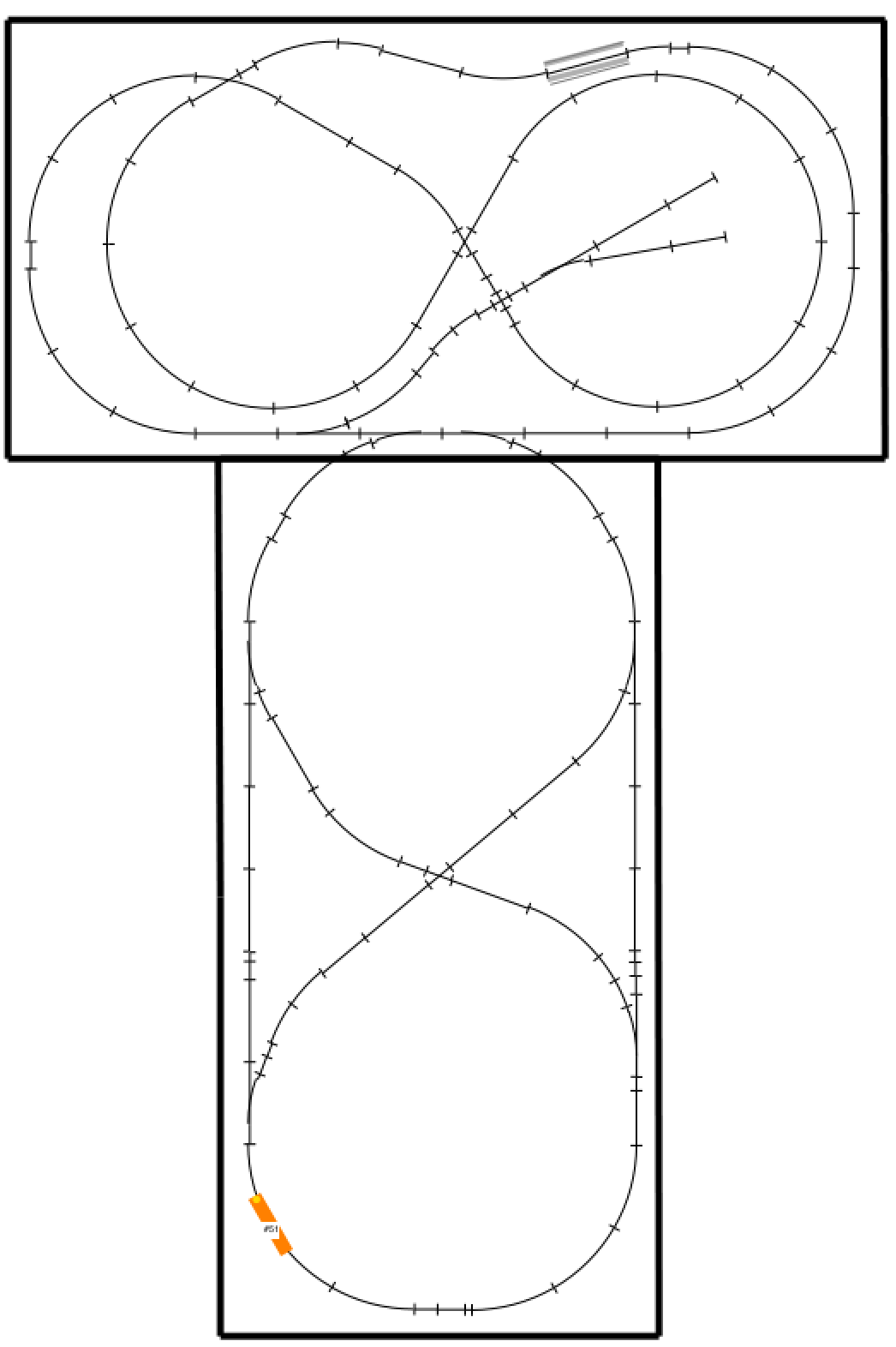 This screen capture shows the 1st attempt to add more functionality with an extension of a 4x8 space. I used a copy of the original plan with its original orientation to start the X-Track CAD program, so adding the 4x8 space to the width of the track plan viewing area didn't work out too well visually in X-Track CAD. I also did not like the "T" shape. 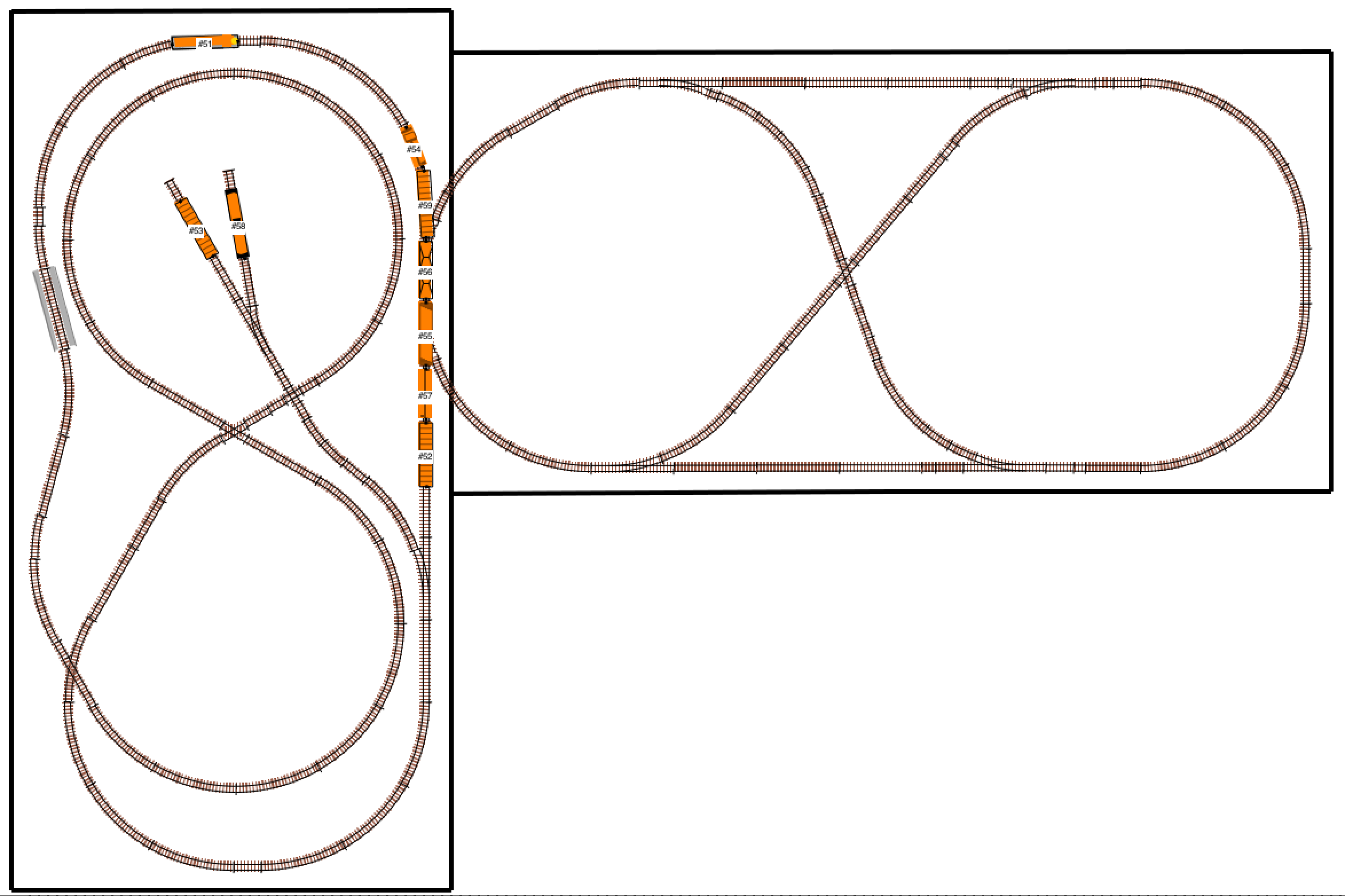 The final attempt at incorporating the Woodland Scenics Grand Valley Layout, into a usable layout for me, created more of an "L" shape, which was okay but... By this time, and after watching more and more Woodland Scenics Grand Valley layout videos on YouTube, along with my research, I decided that this iteration was not for ME. The grades are steep, there is less than 3.5" of clearance where the overpass is in the tunnel, too many of the videos showed too many derailments and other problems and, without some kind of extension, the operations were limited to running a couple of trains and switching a couple of cars at the only siding. While trains can be run both clockwise and anti-clockwise, only one way allows rolling stock to be switched to the siding without using the whole layout as a run around track. It was time to literally go back to the drawing board. 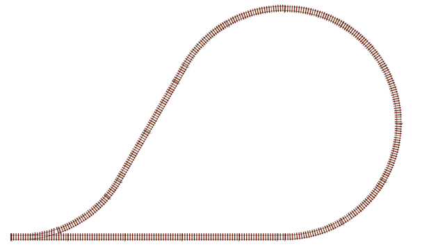 I had previously drawn up the smallest reverse loop to use 18" radius curves. 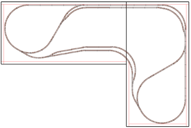 I used that information to create an "L" shaped track plan on two 4x8 spaces. This track plan had a lot of potential with two fairly long passing sidings that could also be used as run arounds with many potential places for sidings to provide a lot of operational interest, I played with this track layout idea for a long time. I realized that this track plan and total layout might just be "too much for ME " to take on at this point in my life. I decided to "modify" that plan, so that the right 4x8 space could be added at a later time, if ever. The next track plan mirrored the left 4x8 space with a 4x4 space extension making it a 4x12 space size. 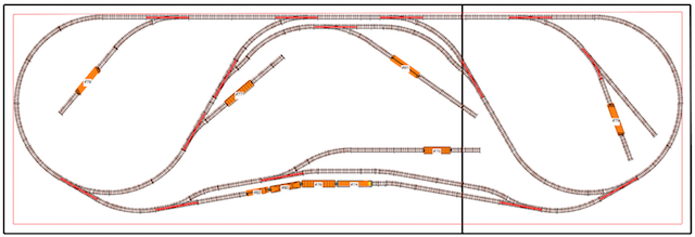 While this track plan was not finalized at this point, I could see that it could provide a lot of operational interest. It also met the other criteria I had in mind. I can also "live with" the restriction that a 4' (48") width restriction puts on the track radius, which limits the types of locomotives and rolling stock that can be used on the final layout. Since this track plan was based on the previous "L" shaped plan, there was already a future extension possibility in place. The following is a list of goals and constraints that I set for my operational layout. Some were thought of before I even started considering a track plan. Others evolved during the track planning process. Use Dead Rail/Battery on Board to power the locomotives
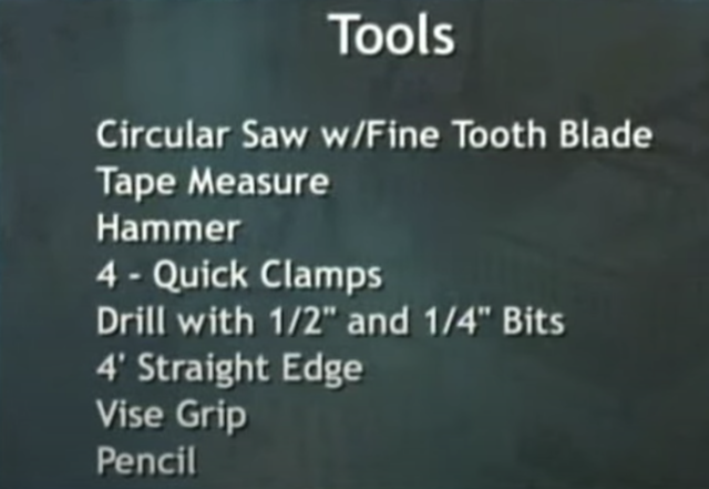
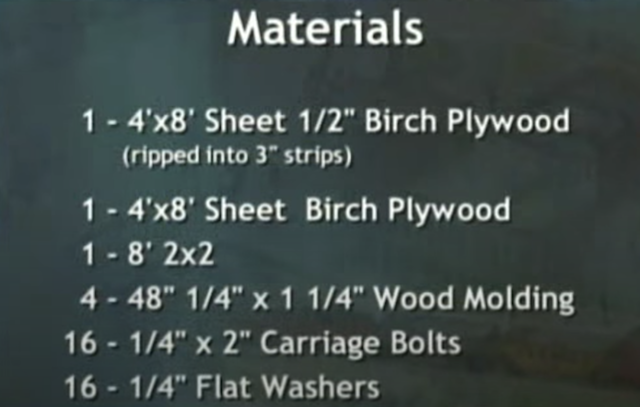
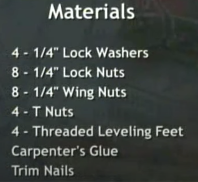
The "Benchwork" The track and roadbed needs to be attached to some type of table top, or other type of benchwork, to become a model railroad layout. Traditionally, the benchwork, either table top or "L-girder", is created using wood products, and more recently adding foam insulation board on top of any plywood used to help deaden the sound of the running trains. The screen captures, below, are from the videos and show the lists of tools and materials required to build the layout with traditional materials. The following three YouTube videos, for a 4' x 8' table top type layout, were used to gather the following information about a traditional table top layout's construction. Build a model train layout: Model railroad benchwork train table how to WGH Part 1
The creators of the videos did miss a few things including;
It can be seen that even building quite simple benchwork requires a lot of tools and materials. The good news is that, because of its size and removable legs, this simple layout can be easily removed when the time comes to do so. More complicated layouts require some destruction to be removed, and the layout might not be able to be reassembled and restored easily. My goal was to create a functional 4'x12' layout that could easily be moved and removed without a lot of destruction and reconstruction, if desired. To keep it as simple as possible, a simple walk around, free standing benchwork was designed for the layout. To keep with my "out of the box thinking" regarding a light weight, easily moveable and removeable layout, I decided to use 2" thick, high density, 4x8 insulation foam board as the base with no plywood under it to create the table top. The NMRA "Beginners Guide Part 3: Building Benchwork" noted that this could be a possible choice. It states, regarding high density foam insulation board, "Although not really needed for structural support, many modelers lay down a thin sheet of plywood ..." Pricewise it worked out a bit less expensive than 1.5" insulation foam board on top of plywood. Both Lowes and Home Depot wanted $79 to deliver two pieces of this foam insulation board. I rented a Lowes' pick-up for $19, plus Michigan's sales tax of 6%, and saved myself about $60 by bringing it home myself! Even though I took the time to hand-pick the foam insulation board, all of the sheets contain small gouges, ripples and imperfections, and they don't seem to lay perfectly flat. The same NMRA article also indicated how high the benchwork could be. Their statement regarding benchwork height, "This is a matter of personal preference and the height of the modeler. However, somewhere in the 38" (96.5 cm) to 52" (132 cm) range is comfortable for most modelers." To be used as legs and table top support, I explored the idea of using Velcro™ to stick the foam insulation board to the top of four 48" long by 24" wide Lifetime Height Adjustable Craft Camping and Utility Folding Tables. Using four of these tables could be a very quick way to support the foam insulation board at a 38" height, as the tables can be set to a height of 36". The process would be very simple. Place some strips of sticky-back Velcro™ on the bottom of the foam insulation board, with matching pieces on the table tops, and the benchwork could be created almost instantly. Unfortunately, that idea had some drawbacks for me. The turnouts have to be manually thrown on top of the layout, as placement of below benchwork turnout machines, like the Fast Tracks BullFrog Manual Turnout Control, would not be possible, but being an "island" style layout, manual switch machines, on the top of the layout, are doable. While there is no under benchwork wiring required to run Dead Rail/Battery on Board locomotives, wiring for lights for structures or other lighting accessories would be somewhat difficult. Next, I decided to explore another option for the framework and legs, commonly available PVC pipe. 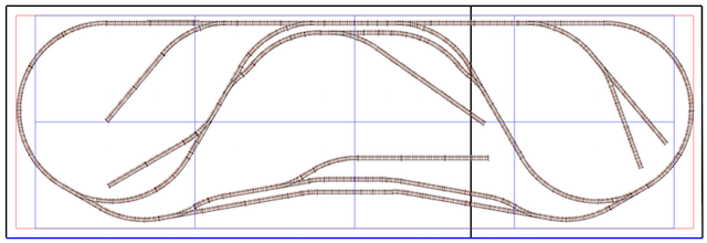 The black lines shown in the X-Track CAD drawing represent the two foam insulation boards. The red lines denote a distance of 2" from the "table's edge" and the red lines run underneath the blue lines that show the PVC 11' (132") by 44" frame top. To be able to use under the table turnout controls with the two furthest left turnouts, the turnouts were relocated on the track plan. 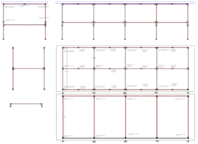 To get an idea of how many 10' lengths of 3/4" diameter PVC pipe and what fittings were required, I created a CAD drawing. Update 03/07/2023 I would tack glue, with hot melt glue, an appropriate number of 3/4" PVC pipe cross pieces across the top width of the frame and spaced about 12" inches apart. The Kingspan Insulation R- 10, 2-in x 4-ft x 8-ft Unfaced Polystyrene Board Insulation is only nominally 4' x 8'. One piece measured 96-1/4" x 47-7/8" and the other measured 96-3/8" x 47-7/8". A carpenter's square was used to check the squareness of each piece, and they were both found to be reasonably square. Update 03/07/2023 I DO NOT RECOMMEND USING THE KINGSPAN BRAND OF FOAM INSULATION BOARD FROM LOWES. Use the Owens Corning FOAMULAR 250 2 in. x 48 in. x 8 ft. R-10 Scored Squared Edge Foam Board Insulation Sheathing from the Home Depot. Cutting across the 4' width, using an Anvil 18 mm 7-Point Snap Knife was not that difficult. 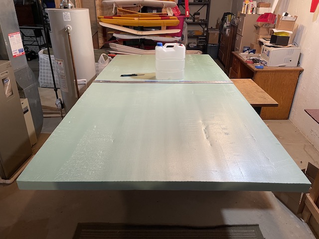 The workbench was pulled out and the nominal 4' x 8' foam insulation board was centered on it. The 4' cut was marked using a 4' metal rule and builder's square to be sure it was a square cut. The 4' metal rule was taped into position using painter's tape and weight was placed on the foam insulation board. The Anvil 18 mm 7-Point Snap Knife was used to score the foam many, many times from each side of the workbench. The knife was held at a 90 degree angle as much as possible using the metal rule as a guide. 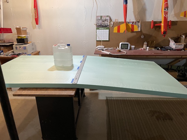 Once the many, many scores were completed, the foam board and weight were moved so that the scored line could be cracked over the edge of the workbench. 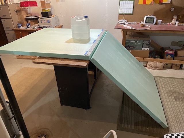 It cracked relatively cleanly. 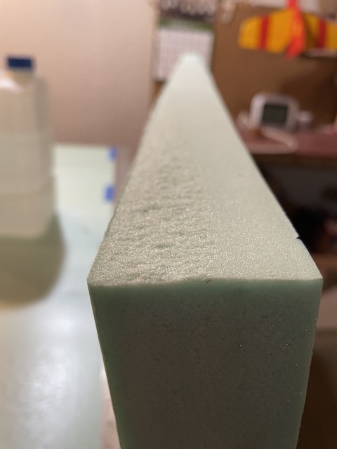 The section that was broken off was originally planned to be used, but the section that was on the workbench made a better butt joint with the other 4' x 8' foam insulation board, so it was used. That made the total length 144-1/2", which was fine. Aleene's Tacky Glue was used to butt join the two pieces. Wax paper was placed on the basement floor at the joint and a 4' level was used to align the two pieces of foam insulation board. 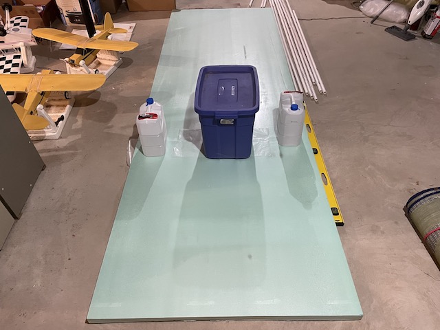 Wax paper was placed across the top of the joint and then weights were added on the top. The extended foam insulation board was allowed to dry. I had used Aleene's Tacky Glue before with foam projects. This proved to be a mistake. With the wax paper on the top and bottom of the butt joint, air could not reach the glue and allow evaporation. After two days, the glue had still not "set up". I would recommend using a different glue for this butt joint. 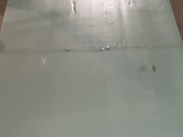 More Tacky Glue was applied to the butt joint with the wax paper off and allowed to dry thoroughly. Packaging tape was wrapped around both sides of the butt joint. Cutting the PVC Pipe
First I tried a 1-1/4 in. Ratcheting PVC Cutter. Even after practicing with it for quite awhile, I was not able to get close to "square" cuts. I don't recommend it!
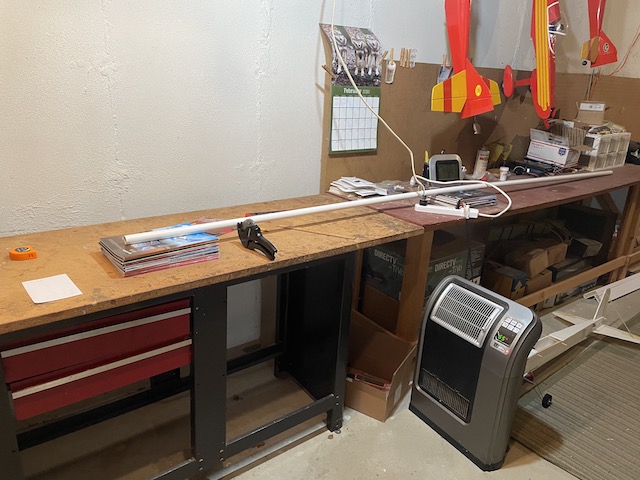
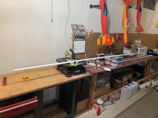
I used my Rockwell Blade Runner X2 Portable Tabletop Saw to cut the pipe to the desired lengths. While the pipe was still not cut totally "squarely", the cuts were a lot more acceptable than those provided by the ratcheting pipe cutter The 10' pipe length was set on magazines and a plastic box to raise the level so that the pipe was resting on the saw correctly before cutting.
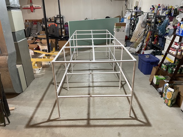
After the pieces were cut to length, based on my CAD drawing, the frame was assembled on its top and then turned over, as shown in the photo.
The foam insulation board was set on the frame, but not attached yet using Sticky Back Velcro™.
The foam insulation board was turned over. The PVC pipe frame was placed and aligned on the bottom of the foam insulation board table top. Once aligned, the Velcro™ strips were cut and put into place.
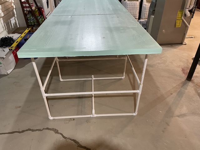
The protective plastic strips were removed from the 2" bottom pieces and stuck to the table top. The 6-1/2" pieces were tightened between the two inch strips. They had their protective plastic backing left on them. The whole unit was uprighted. I felt that the benchwork was a bit too wobbly when just sitting on the 10 legs.
I researched and found a "better way" to do the legs. The method I found is shown in the photos, and it significantly reduced any wobble in either direction. This type of leg construction, at each end of the frame is ABSOLUTELY ESSENTIAL. At this point, Nov. 12, 2022, the foam insulation board measured 47-7/8" wide, 144-1/2" long and the top of the table sets 40-3/4" above the floor.
15 - Charlotte Pipe 3/4-in 10-ft 480 Psi Schedule 40 White PVC Pipe
The following is not commonly stocked and had to be ordered
Exactly one week after completing my PVC pipe leg work, the following was put up on YouTube. 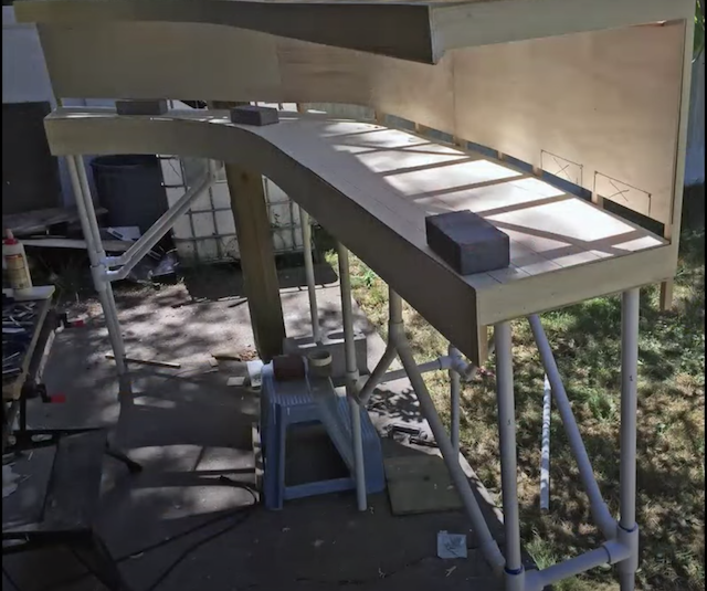
Screen Capture from "What's Neat This Week", Nov. 19, 2022 While watching "What's Neat This Week in Model Railroading #216 November 19th 2022", I was quite surprised to see a PVC pipe frame being used on a modular layout design. Using 45 degree fittings seemed to be a good idea. After attending a "Train Show" in East Lansing, MI on Sunday, Nov. 13, 2022 with a flying buddy who also does trains, he came into the house and I showed him the table and my latest proposed track plan. He liked the table idea, but noted that HE preferred a track plan that allowed more than one train to continuously run at a time. I knew that wasn't my intention, but that thought played on my mind for several days. I created a "new" track plan in X-Track CAD. The new plan allowed two trains to run continuously and possibly a third to do some switching with up to three engineers running trains. That was a very different goal than I'd originally intended with just one engineer, me, running a train and doing some switching. Is that possibly a bit of a paradigm shift? 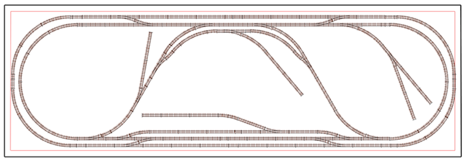 Use Dead Rail/Battery on Board to power the locomotives
With the realization that the thinking and planning stage could go on forever, I said to myself, "ENOUGH ALREADY!" 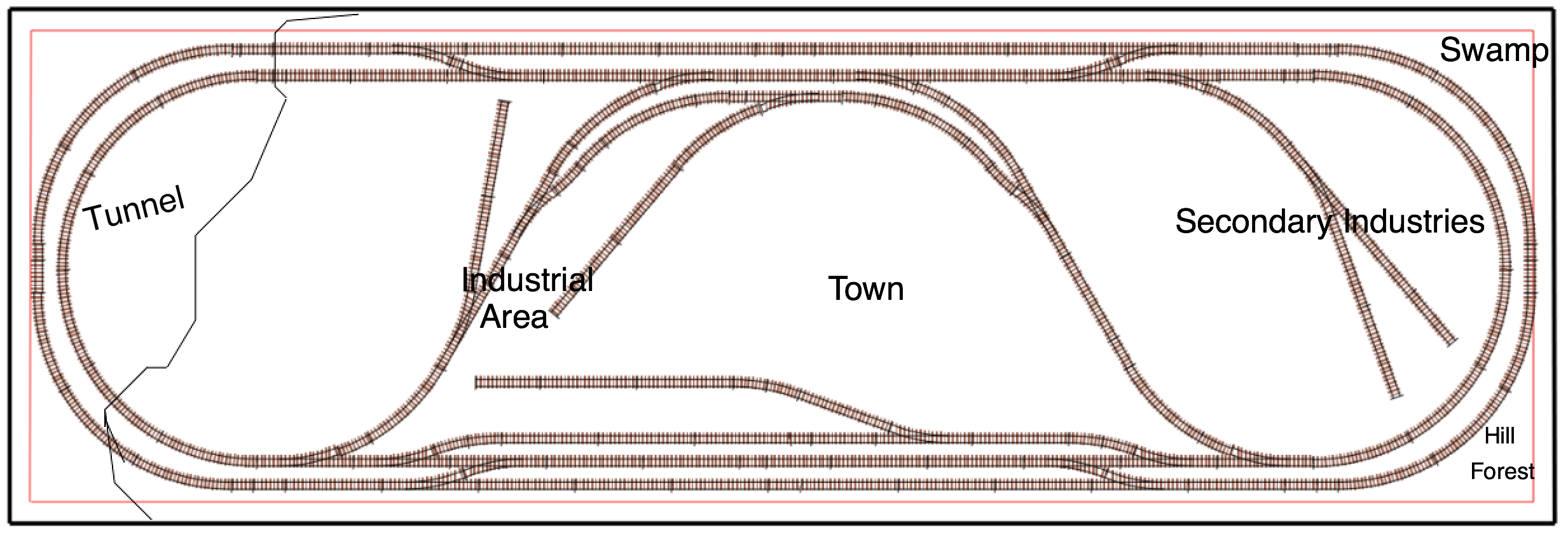 I had a couple of final thoughts before purchasing the track. I created a very quick "sketch" of what was in my mind at the time. The "sketch" provided a very rough idea of scenery placement and a slight track plan change. Then it was time to calculate the needed track and procure it.
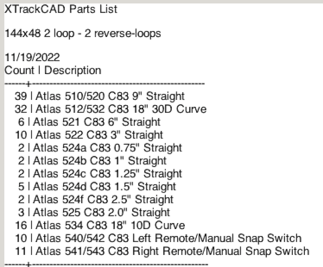
One of the features of the X-Track CAD program is that it provides a required track parts list for the completed track layout. 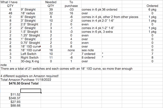
Inventory & Shopping List Spreadsheet An inventory was created of the Atlas Code 83 track that was on hand from the building of the Demo Layout. The inventory included the track that had been used on that layout. "Back in the day", obtaining the track could have been quite easy. Go to the local hobby shop. Select and purchase the track pieces. Return home. Start assembling the track on the benchwork top. Unfortunately, the local hobby shop didn't have even one Atlas HO 542 Code 83 Left Hand Manual Snap-Switch Track or Atlas HO 541 Code 83 Right Hand Remote Snap-Switch Track. An attempt was made to purchase all of the required track from a single supplier. It failed because no Internet suppliers, at that time, had all of the required track. After several frustrating hours of searching various Internet suppliers, Amazon was used for the purchase of the track. The criteria used for purchasing the track was that it had to have free shipping and be in stock. Price was only a secondary consideration, if even a consideration at all. Unfortunately, free shipping of the turnouts was not available unless I wanted to pay more than the current list prices of the turnouts. Free shipping, not! All four orders, to various suppliers on Amazon, were placed on Friday, November 18. Three of the orders arrived on Monday, November 21. The other order, that was shipped from the SELLER Winkie's Toys & Hobby, with all of the Atlas Code 83 switches, was not shipped until Monday, November 28, 2022. Only part of the Order arrived on December 2. That was 14 days, two weeks, AFTER the initial order was placed! Unfortunately, it was only a part of the initial order. Regarding two of the Atlas right manual switches, there was a hand written note on the invoice stating, "2 will ship separately". What was even stranger was that the package was sent 2-Day Priority USPS Mail. All of the items were suppose to be in stock on the day they were ordered. The two right switches showed up on Monday, December 5, 2022. This whole process did not go smoothly! Atlas 521 HO Code 83 6" Straight Section 4pcs - Ships from Y2PLAY = Sold by Y2PLAY - SELLER Rapid Warehousing
I would love to know the difference between Ships from/Sold By and the SELLER? I do not understand the difference at all! I should have gone to a "real" train store, with a presence online, such as Yankee Dabbler and avoided Amazon completely. I continued to watch a lot of YouTube videos on creating scenery. The use of Woodland scenics 2" risers was considered. After realizing where all of the platforms would have to be placed for the various industries, town areas and the like, I realized that using risers, for a more dramatic landscape, was probably not a good idea. While the original plan was to use under-the-table turnout throws, Caboose Industries HO Ground Throw Sprung 5 CAB5202S HO Track manual throws were ordered through Amazon to give them a try, since the layout is an island and the train controllers are cell phones and moving around the layout is not difficult. The YouTube video "Caboose Industries Switch Throws on Atlas Turnouts" showed which number to use with the Atlas Snap Switches and how to install them. Caboose Industries HO Ground Throw Sprung 5 CAB5202S HO Track, ordered Nov. 26, 2022 & delivered Nov. 29, 2022.
It took awhile, but I finally realized that I probably had enough track to mostly set up the main line track to see if the track plan, created in X-Track CAD, would actually work. All of the track was removed from the demo layout. That track, along with the new, ordered track that had arrived, was set up on the table top, using only the original 6 turnouts from the demo layout using the X-Track CAD plan as a guide. To paraphrase Robert Burns, "The best-laid track plans of mice and men often go awry!" In the real world, the reverse loops, as shown on the X-Track CAD track plans, did not work out physically! The tracks would not meet up correctly as shown. 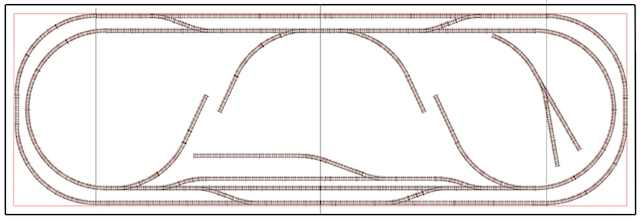 It was time for a plan B. Over two days were spent trying revisions to the X-Track CAD track plan and then laying the revised plan out on the table top. Much of the time it failed, as demonstrated in the screen capture above. 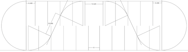 On the third very frustrating day, I used my CAD program to create the reverse loops and get the correct measurements. The measurements from my CAD drawing were input into X-Track CAD. Once the reverse loops were set up on the table top, it became apparent that the original track plan needed major revision. 
This is Revision 4. The red lines are 2" from the table top edges. It appeared, at that time that the run around, with its siding, could not be achieved between the reverse loops if sidings were also to be placed coming off the inside of the reverse loops. This later proved not to be true. A passing siding was added to the "far side" of the layout to use the space and also to use the Atlas switches that had been ordered for the original layout. The passing siding was later eliminated. When the track plan was laid out on the table top, without all of the turnouts available, it appeared that it was going to work, but another Atlas Railroad HO Code 83 Straight Assortment had to be ordered to complete all of the track connections. It was ordered from Amain Hobbies on Tuesday, November 29, 2022 and arrived on Friday, December 2, 2022. Re-inventorying also showed that more 2" sections were needed for the completion of Track Plan Revision 7. A package of 2" Code Atlas 83 was purchased at Nankin Hobby in Farmington, MI on Thursday, December 1, 2022. The track plan was actually revised 14 times. 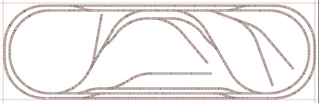 The overall track plan 14 then looked like the above, but... Once ALL of the track was available, it was laid out on the table top. Each time the track was physically laid out on the table top, it still had a problem. It seems that the X-Track CAD track planning program has a problem when using Atlas sectional track on a diagonal. Once the majority of turnouts arrived on November 28, 2022 I put in many, many long days placing track on the table top, finding that it did not work and then working with a new version in X-Trach CAD.
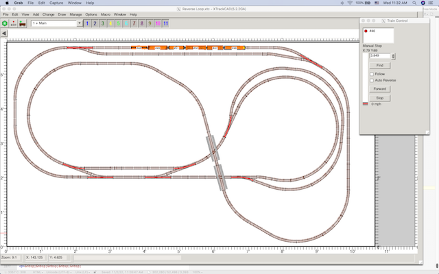
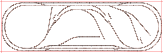 I knew that tha physical layout did work, I could see it, but the X-Track CAD drawing showed this. The two sections of track near the reverse loops are the actual length used on the physical layout, but are too long to fit in the open space shown on the track plan. The 6" section of track near the end of the "Y" spur, farthest to the right, actually fits physically, but not on the X-Track CAD drawing. One good thing was that the curves. entering and exiting, the reverse loops lined up in a straight line on the X-Track CAD drawing for the straight sections between the reversing curves. |