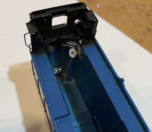
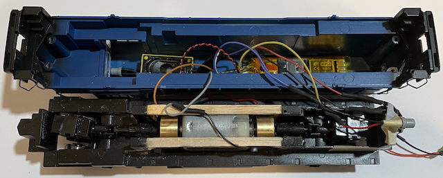
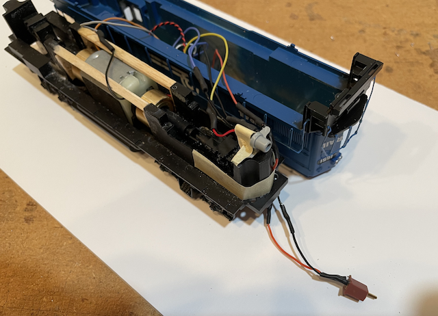
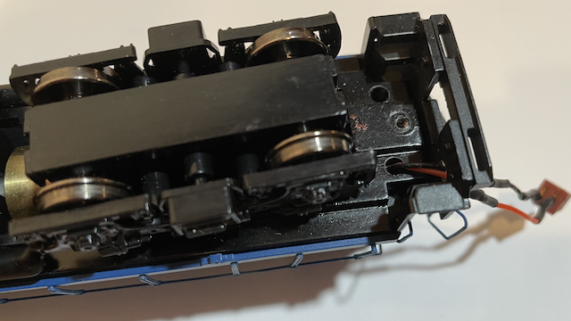
 The bottom portion of the right, rear screw holder was removed to allow the power wires from the decoder to drop down through the frame whole where the screw would have been attached.  LocoFi™ was easily installed and the speaker and decoder attached with tape.  The power leads for the decodeer are tucked under the right wing of the rear light bracket and taped in place. (Note: There is an oops shown in this photo. Can you spot it? Hint: It has to do with what's on the end of the power leads that shouldn't be there yet. At this point, I decided to use no connectors. I used no connectors, just "hard wiring" between the locomotive and battery car for many months. In September of 2022 I decided to use the MicroMark Micro Connectors as they are small and work very well.)  The shell is placed on the chassis and then the power leads are run through the screw hole and then threaded through the hole in the rear of the shell. The connector was then soldered on. (That was my oops.)  The rear coupler was installed and the unit was placed on the demo layout and tested in all directions while paying particular attention as to how the unit handled all the turnouts while running in each direction. After passing the running test on the demo layout, it was time to set up and configure the locomotive following the directions in the two LocoFi™ videos found on the LocoFi™ videos page. |