The following day the train set oval was set up and the locomotive was run in forward and reverse. At very low speed, right out of the box, it appeared to be a bit jerky in both forward and reverse when compared to the other two examples of this same locomotive that I have when they were run right out of the box. The locomotive was run for 10 minutes, at full speed using the train set's DC controller, in both forward and then reverse. After the brief run-in for 20 minutes, the lowest moving speed was still jerky. 
Note the red stripes on the gearbox covers Unlike Kadee coupler gearboxes, it is difficult to discern the correct orientation of the cover on the Walthers' gearboxes. The coupler gear boxes were striped with red paint to note the orientation for reattachment. 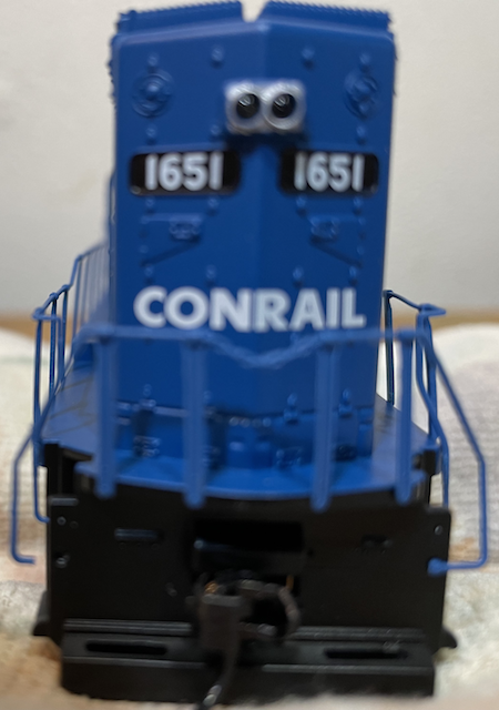 Before doing anything else, it was noted that the rear, left, bottom grab rail was missing its push in pin part and not attached as the pin was gone. 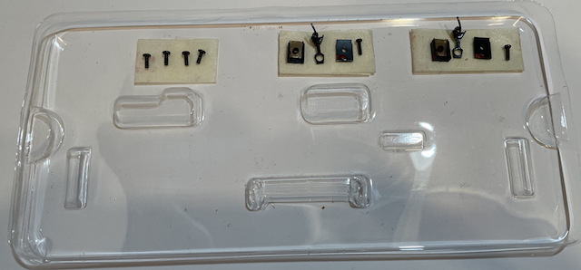 The couplers and gearboxes were removed using a Phillips 00 size head and placed on flat, folded masking tape that was stuck to the plastic cover for this locomotive. 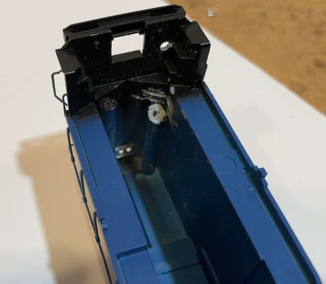
Note the 9/64" hole in the shell and bottom portion of screw holder removed A 9/64" hole was drilled on the right side bottom of the body shell, near the coupler and aligned with the right side screw frame screw hole, as an exit for the battery wires. The four screws, holding the body to the frame, were removed and the body shell slipped off the frame, which required the headlight LED to be slipped out of its socket in the body shell. 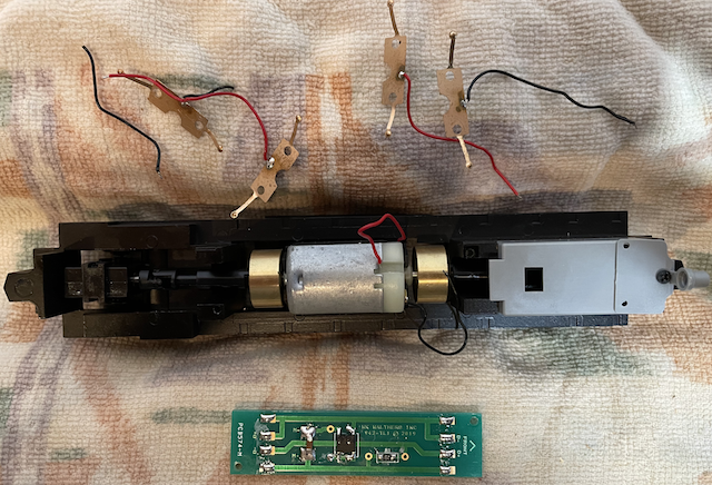 The pick-up wires, motor wires and LED Light wires were unsoldered from the PCB. The PCB was unscrewed and removed. The pick-ups were removed from the truck wheels by removing the truck side frames and pulling the pick-ups out with tweezers. A Dremel, with a cutter bit, was used to remove the bottom portion of the right screw holder to allow the power leads to exit through the right side, rear frame hole as shown in the previous photo. A 9/64" bit was used to enlarge the right, rear screw hole in the frame for the power leads to pass through. The gray box at the end of the frame was left in place. The LocoFi™ decoder, with its attached speaker, and the front and rear LEDs were removed from the broken Conrail, after cutting the motor leads. Folded masking tape, so that the sticky was on all sides, was used to secure them in place in the second unit. The power leads were run out through the right, rear screw hole and the motor wires soldered to the wires from the motor that were previously attached to the now discarded PCB. The motor wires from the decoder were soldered to the motor leads of the new locomotive. 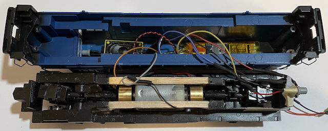 The photo is of the original installation and shows the parts placement. In this installation, into the new Conrail, there is no framework over the motor and the gray box, over the rear truck is still in place. (Forgot to take photo before screwing the body shell to the framework.) The body shell was mated to the frame, but the screws were not put in at this time. The power leads were soldered to the leads with the Micro-Mark connectors that go to the battery car. Four Soshine LiFe AAA size batteries were placed in the battery boxes in the Soo Line boxcar/battery car. The Micro-Mark connectors were connected and there was the familiar "click-click" of the decoder receiving power. The front two, and the remaining rear screw were screwed into the frame, thus attaching the body shell to the frame. The rear stock coupler was attached, which is always fiddly, and the Kadee #147, with its gearbox, was attached to the front. Even though the LocoFi™ App had not been configured for this new Locomotive with its battery car, it was run on the layout for about 15 minutes with no signs of derailments.  Notes on the configuration process for this locomotive are archived here. |