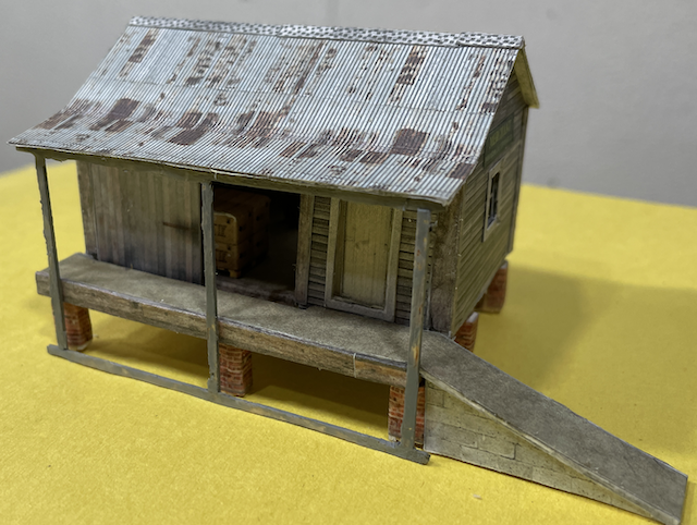
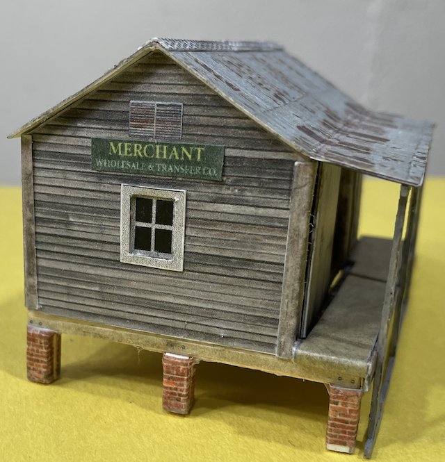
By Ken Myers September 2024
A lot of time was spent trying to understand why so many model railroad structures just didn't look "right" to me. The archived research was saved as .pdf files and can be found here.
09/10/24 Preparations The basement work area was straightened up and a lot of things were put away to clear the workbench. A tri-color 65XL HP cartridge, an AK Interactive Ultra Matt Varnish and an AK Interactive ultra matte varnish #183 were ordered from Amazon. The two varnishes were ordered per the recommendation of Michael Scott the creator of the YouTube channel Chandwell. (The varnishes caused the printer ink to smear and run and were not used.) Before ordering the free Small Goods Store from Scale Scenes, Google was searched for videos of Scale Scenes structures to learn how their kits were put together. Scalescenes was used as the search term and the results of the first page were viewed. Several of the videos were viewed. Two terms, or key words, kept coming up in the videos; Inkscape and Cricut cutter. 09/11/24 The doors of this small structure were to be left in the open position. This meant that the wall thickness, around the open doors, was an important thickness to note. I first noted an observation from the previous constructions that I had completed; doors that open out of the building sit at the front of the wall and those that open into the building are recessed. There is a threshold under the door. Windows are set in about 1/2 the thickness of the wall of a frame house. I calculated that a full scale wall thickness, of this type, would be about 4-5/8" thick. In HO scale that would be 0.0531609" or x 25.4 for mm equals 1.3502869mm. 1mm is about 0.039" or 3.43" in HO scale and 2mm is about 0.079" or 6.85" in HO scale. 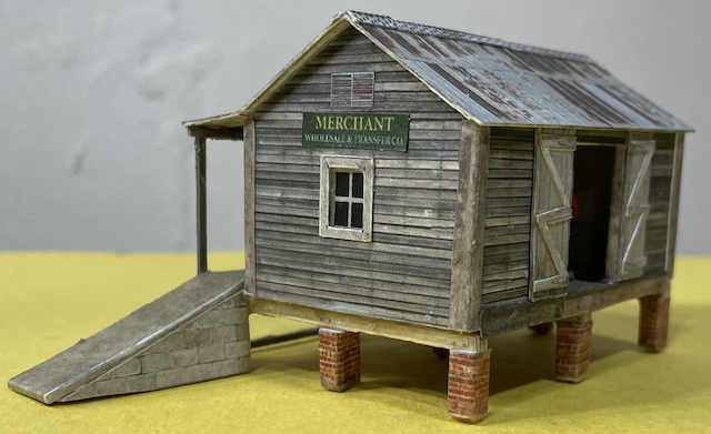 The photo of the open hinged doors demonstrates that by adjusting the wall thickness, by not using two 1mm thicknesses back to back, as noted on the plans, the resulting wall thickness did "look right". The Small Goods Store, in OO scale, had been downloaded the previous day, on September 10, 2024. All three sheets of the textures and plans were printed in black and white at a reduction of 87%. OO scale (1:76) divided by HO scale (1:87) equals 0.8735632 or 87% when rounded. This also served as a test to demonstrate that a whole page of textures, reduced to 87% for HO scale, would fit on an 8-1/2" by 11" sheet of standard US printer paper. The entire instruction sheet was carefully read through, while studying the printed parts. Looking at Step 13: The Wall Corner Caps are not the same width on each side of the building. One is 3.5mm wide and the narrower part 2.5mm wide. From the photo of this step, it appeared that the wider 3.5mm side of the corner cap goes on the long side of the structure. It says, "Print Only" for these parts, but coloring the edge of just a paper thickness was going to be difficult. The textures were affixed to 110lb. card stock. The 110lb. card stock is about the right thickness, 0.008" for a full scale 3/4" (0.75") thickness. 3/4" divided by 87 = 0.0086207". There are two different textures that can be used on the exterior of the structure but both versions use the same interior wall textures. The texture wrap for the piers notes centre & end. By end they mean facing out. The end portion measures 3mm wide. For a personal modification, windows were to be added to the short ends of the building. I did some research and found a 4 grid, double hung window at Home Depot. Its dimensions were used for the model window. Grid width: 1" (I can only use 1.5")
A window was created in my 2D CAD program, based on the previous measurements, but the positioning, on the wall, was yet to be determined. A video was watched where a fellow said that the size of card stock matters when building Scale Scenes structures. (This later came back to haunt me.) 09/12/24 Preparing to Print the Textures All three texture pages could have been printed, when reduced to 87% for HO scale, on standard, 8.5 x 11, US printer paper. I chose not to do that as there are two possible textures that may be used for the exterior, with only one being required, as well as a lot of extra text that did not need to be printed. Because I didn't want to waste ink, although it does waste a bit of paper, and because I knew that I'd make mistakes and have to reprint some of the textures, I used the method described in the YouTube video titled, "2022 Update: How to Take a Snapshot In Adobe Reader for Printing". The captured area had to be printed at the 87% reduction. 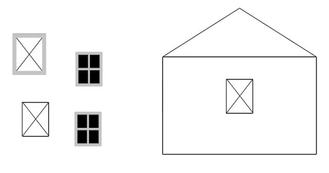 A full scale size 2D CAD drawing was made of the wall and window I wanted to add. It was printed at 100%. The two joined short walls of the clapboard texture were printed at a reduction of 87%. Both prints were compared. The printed walls fit fine, but the vertical of the window was not wide enough. I changed that. The two short wall textures, still joined, were affixed to some backing board (about 1mm thick). They were then cut to shape. The new 2D CAD drawing was affixed to one of the backing boards with a glue stick. From the 2D CAD side, the window opening was cut out. The printed window was cut out, without the frame. About 1/4" of white paper was left around the window for gluing. The window was glued to the inside of the short wall piece behind the cutout for the window. Aleene's Tacky Glue was used to affix the window to the back of the wall, and that wall was later covered by the inside wall. 09/13/24 The 2D CAD drawing of the window frame was one piece, and it worked well. An interesting technique was used to cut out the frame once it was attached to some 110lb. card stock. The outside of the frame was cut out first. The edges were grayed with a pencil lead. A very small dab of glue was placed in the center of the backside of the frame. It was then glued to some printer paper by the dab of glue on the backside. The inside of the frame was cut out of the frame piece. I was able to lift the frame from the paper, leaving the center glued to the paper. The inside of the frame edges were then grayed with a pencil. Aleene's Tacky Glue was used to affix the window frame to the short wall to allow better positioning time than a glue stick. Both exterior short walls, with their windows, were completed today. 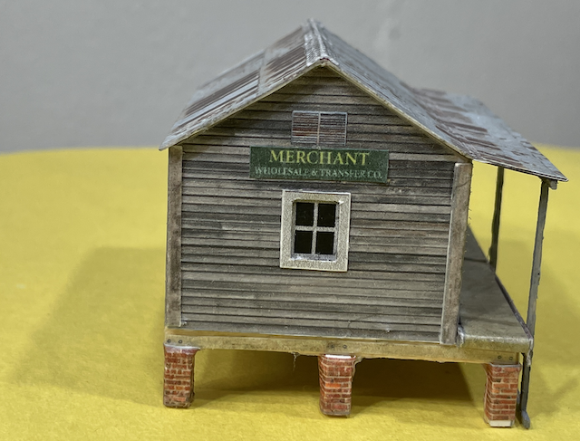
A completed short wall is shown well in this photo. 09/14/24 A personnel door from the Clever Models O scale Crossing Tower was added to the long side with the ramp. The door was printed in HO scale by reducing the original door by 55% from the original O scale sized door. The Scale Scenes' instruction sheet and plan sheets were carefully studied again. If Medium Card (1mm) was used for both the interior and exterior walls, it would creates a wall that is 7.1" thick in HO scale. Even in OO scale (1:76) the wall would be over 6" thick. That would cause a problem with the sliding and hinged door openings, as they were to be glued in the open position on the long walls. The walls would be too thick in appearance. 0.011" poster board was used for the long side interior walls. The hinged and sliding doors were supposed to use Medium (1mm) card stock, but again, that was too thick to be "scale". It appeared that the use of the 0.011" thick poster board might cause a problem with the platform gap for the sliding door. The gap appeared to be 2mm in width. In the end, it didn't turn out that way. The two pieces of poster board (0.011"), when laminated, worked out well. While not at this point yet, I had to remember that the texture wrapping for the pier bricks needed to be cut into three sections. I created a CAD drawing for the long side with the ramp for the insertion of a personnel door into that wall. The CAD drawing was printed. Cut out on the outside of the lines, it was a little bit big, but the door, overlaid on the printed door outline, looked just about right. 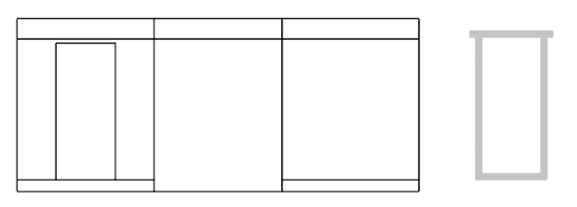 The screen capture shows the placement of the personnel door from INSIDE the structure on the ramp side. The 1mm backing board was quite difficult to cut. During construction, the short wall end beams, with their piers, were not built as a single unit as describe in the instructions. 1/8" balsa wood was used to create the beams and inside "legs" of the piers but the 1mm backing board was used to create the Part A pier parts. As a test, the center beam was completed, at this time, to check the beam texture and brick wrap texture. It worked fine. The matte varnishes, which had been ordered through Amazon, arrived on September 10, 2024. The AK Interactive Ultra Matt Varnish was used on the test piece of the short wall. The varnish made the printer ink run and blur. The test piece had actually been printed many days ago, therefore the ink had had plenty of time to dry. It looked like the construction of the long walls was going to be a problem. It didn't seem that just scoring between the exterior long walls and exterior floor would allow the exterior walls to wrap up onto the top of the floor. A test piece was made using a CAD drawing of the exterior floor and long walls. It appeared that the long walls had to go on top of the exterior floor but that the door opening had to protrude to the edge of the exterior floor. The test piece could not be completed successfully. Another possible problem was that the 1mm card stock, recommended as Medium by Scale Scenes, is NOT the same scale thickness as for HO scale. For HO scale, Medium card stock should be 0.87mm thick. That seemed to be a problem, but it really didn't turn out to be one. As stated earlier, 0.87mm would be 0.034252" when dividing by 25.4. The caliper, or thickness, also known as point (pt), of the cardstock that was on hand was verified. 110lb. Card Stock - 0.22mm or 0.0086614"
The backing board was a tad thicker, compared to what was considered as Medium cardstock for Scale Scenes. The other two are way too thin!!! I became very concerned about this discrepancy and did more research, especially since the video linked below notes that this can be a problem.
I visited the Scale Scenes page; "Not modelling in OO (1:76) or N (1:148) scales?". The research, on card thicknesses, was archived as a PDF for future reference. The Salient Points From the Research
09/15/2024 After all of the "cardstock research", 3 scrap pieces of backing board were put together to be used as a thickness gauge. The thickness gauge was laid up against the printed plans for the end pier texture covers, as they were supposed to be 3mm thick, and it seemed to work fine. Now what?
The exterior bottom and exterior walls were cut apart. That allowed me to do the cutting on the back of the exterior wall with a razor blade and then texture cover the exterior walls. A long wall CAD drawing, for opposite the ramp side, was created. A lot of time was spent with very little to show for it. When printing the front long wall for the first time, I forgot to mirror the template for use on the back of the wall. It was mirrored and reprinted. The openings for the personnel door and sliding door were cut out of the ramp side long wall and then the rest of the long wall was cut. The front texture print was glued, using a glue stick, onto the long wall piece. The door frame, for the personnel door, was cut, but it could not go on until the ramp was in place. The personnel door print texture was affixed, over the opening for it, in the back of the exterior, ramp side, long wall. Unfortunately, it was not a good job. It was torn off because it just wasn't quite right. This had been a very frustrating day. The kit instructions are, at times, somewhat vague. Many times the photos, accompanying the instructions, don't help all that much either! From my experiences in cutting the backing board, I didn't think I could cut out the 9 pier parts labelled A. Fortunately, later on, I was able to do that, since they were all straight cuts. I recalculated how closely 1/8" balsa would be to 3mm.
To make the piers, the following dimensions for the piers were measured;
09/16/2024 The pier parts were assembled. The center part of the piers and beams were cut from 1/8" balsa. Only 9 legs were needed from the 1/8" balsa but, mistakenly, 27 were cut. Oops. After constructing the center part of the pier beams and legs, and assembling them with thin CA glue, I realized that the A parts needed to be only 1mm thick, not 4mm (1/8"). I used the print texture/plan to cut the A parts from backing board. The other two center parts for the piers were made. The piers were finished by adding the A parts, cut from backing board, and then the brick texture was wrapped onto them. The exterior and interior floors were started next, but something was weird with them and I could not figure it out. I stopped working here for the day, as I had worked for 8 hours on this today. Time was taken to trial fit the long sides and one short wall to an exterior short wall. A quick view showed that the exterior wall was too wide by about a millimeter. Still much to do. 09/17/2024 Through much of this article, I had accidentally transposed two digits in the mm to inches conversion factor. The math errors were corrected where I had mistakenly used 24.5 to convert to and from mm and vice versa. It was replaced with the correct factor of 25.4mm to the inch. After casually, and incorrectly, observing that the cut exterior bottom was "too wide" physically, yesterday, I decided to measure the actual black and white prints that I made before starting the build. First, I double checked that the short walls did indeed overlap the long walls on the ends. Step 12 on the instructions clearly showed that. If I had made the short walls with the piers on them, this would have been very apparent. Instead, I wasted a lot of time proving to myself that the short walls overlapped the exterior floor and the long walls go on top of the exterior floor with the interior floor behind the long walls. Unfortunately, that meant that the personnel door was cut out too high on the exterior long wall, because I thought that the floor depth on the long wall was 2mm, but it is only 1mm. It was fixed by remaking the door frame bottom wider. Luckily, the personnel door frame had not been glued to the structure yet. The long interior sides were cut from poster board. They were cut out and held in place on the long sides to see how that affected the interior floor. The interior floor, with its texture applied, was cut out. The completed interior floor was just slightly wider, at the protrusions for the door openings, than the exterior floor. The exterior floor was affixed to the interior floor, leaving about a 1mm gap on each side of the top of the exterior floor on either side of the door openings. The protrusions needed to be sanded to become flush with the exterior floor and there was a gap in one of the door openings that needed some fixing. 09/18/2024 The protrusions of the interior floor were cut even to the exterior floor edge. Everything was trial fitted. The long sides sit ON TOP OF THE EXTERIOR FLOOR PIECE. The interior short walls were created using backing board. The interior short walls were glued to the exterior walls using Aleene's Tacky Glue. They were put under 1-2-3 blocks to dry flat. The door edge coverings were created using cardstock, even though the note on the pieces indicated that they should just be made from the printed texture paper. Once the door edge textures were affixed to the card stock and before cutting them out, the fold lines were scribed on the back side, using pin pricks through the cardstock to align the folds. A dulled awl was used for the scribing process. The cut edges were colored with a sharpened pencil lead used sideways. The folds were made. The door edges fit perfectly. Only the front part of the edge was glued on the long wall at first. The wrapping was completed after the front edge was allowed to dry thoroughly. The matte varnish had already been tested and found unacceptable, but I still tried it on the interior short wall pieces. It looked like it was "killing the color" and was taking a long time to dry. The original test piece, an extra short wall exterior and scrap piece of backing board had previously been made up and failed. Again, a coat of the acrylic varnish was applied to the interior pieces. In a bit, the test pieces were observed. The printer ink colors were definitely bleeding. It was at this point that I decided to spray the whole structure with KRYLON Colormax Flat Crystal Clear spray paint when the structure was completed. No matte varnish was applied to the long interior walls. The door edges were wrapped and glued with Aleene's Tacky Glue. They were then pressed down with wax paper between the interior wall and a 1-2-3 block and left to dry flat. 09/19/2024 A new personnel door was printed and the actual construction of the structure began. After careful fitting, one short wall was affixed to the floor and held in place with 1-2-3 blocks. An hour later, the other short wall was attached. An hour later, the long wall, with the personnel door was glued on. After waiting another hour, the other long wall was attached. I was still very frustrated. The finished photos on Scale Scene's Website and the photos in the instructions are quite different. One corner cap was trial fitted and it looked too wide on the long side. It was cut down a bit, but then it was too narrow. A different corner cap was test fitted and then affixed to the walls. I called it a day. 09/20/2024 Poster board could have been used for the construction of the interior short walls as well. That would have allowed for the narrowing of the corner cap to a more realistic width. Both doors were constructed using cardstock. An extra print of the roof was test fitted to see if the white guide marks on the edge could be cut off so that the edge piece could actually go on the building and not the roof, but it can't. The building was set on the piers and then set on the layout to observe the structures final height. It looked like the leg height would work out okay. A piece of extra corner caps (I cut more than was needed) was made to fit between the ramp and sliding door opening to fill the gap. Trying to figure out how to attach the piers was difficult. The first beam and pier set was glued onto a short end and blocked straight with 1-2-3 blocks. After an hour, more glue was added to that end. The first attempt at doing the roof was embossed and cut out using cardstock. It appeared to fit perfectly, but later, a second, modified roof was actually used. The ramp infills were printed and attached to backing board. These too had to be changed later. The side texture coverings, for the ramp, and the other long side were created. The doors were laminated and placed under 1-2-3 blocks to dry flat. The center pier section was glued to the structure's exterior floor bottom. 09/21/2024 Yesterday, when the ramp was test fitted, it was too short. A new ramp was built to actually fit the model. The OO scale ramp cover texture, printed at 100%, was used to extend the HO ramp to size. This caused a problem with the platform edge being too short. Another ramp edge piece was made that was longer and the OO scale platform texture cover was created to add to the length. All of it was cut out and assembled. The other edge cover was cut to length and added to the double door side of the structure. The hinged double doors were glued to the structure. The infill was glued to the brick pier on the ramp side. It turned out that the infill was WAY off of the ground, by about a millimeter. While the glue was still wet, the infill was removed. After thinking about it, and measuring the parts on my printout in HO scale, I calculated that my cross pier members were too high, compared to how it was done originally. The OO scale printed texture, printed at 100%, was used to create a new infill. The roof, which I already completed did not have an overhang at the short ends, as typical here in the US. I later remade the roof. The ramp was glued to the structure and the new infill was tested toward the outside of the ramp. 09/22/24 I slept on the roof issue and didn't think I could cut out the parts for the idea that I thought about yesterday. I thought about adding a roof over the platform at this point. Again, I slept on it. There was not really enough time today to do any "thinking" work. The front infill was glued into place on the inside of the ramp. 09/23/2024 It occurred to me that the roof capping, or ridge capping, was not going to be long enough for the extended roof that I had in mind, since I wanted to add an overhang over the short wall ends. Home Depot was used for research on ridge caps. Their Web site showed various caps. This cap showed a good color to use. The sections of capping are 10' long. That's 1.3793" (~1-3/8") long in HO scale. They are 20" wide, which is 0.230" (~ 1/4") in HO scale. A CAD drawing of the new roof, with the extension over the ramp, was made. It was physically created, and it worked on the 1st try! That never happens! Three pallets were made from the TeamTrackModels.com ACME Transfer Warehouse kit. I put them in the warehouse and added a HO scale man. 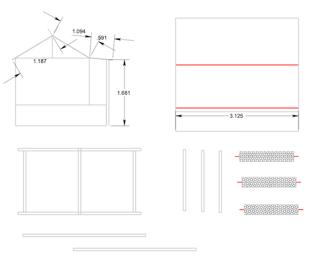 A cad drawing of the platform roof supports and the new roof ridge caps was added onto the drawing for the roof. It took a long, long time to make the frame for the ramp overhang from 1/16" square balsa wood. Thin CA was used to glue the balsa pieces together. 09/24/2024 The acrylic matte was painted on to a test sign for the building. The sign, like the pallets, was from the TeamTrackModels.com ACME Transfer Warehouse kit. The acrylic matte made the ink on the print run a bit, which was what I had expected, and just the effect that I wanted. Two of the signs were printed at 60% of the original size from the Transfer .pdf. Matte acrylic was painted on both of them and they were left to dry. The ridge caps, which were made yesterday, were attached to the roof. The roof was attached to the building. The balsa wood frame/post unit, used to hold up the roof over the ramp, was washed with a mixture of acrylic white, gray and black paints. When the paint dried, the frame was glued to the structure. 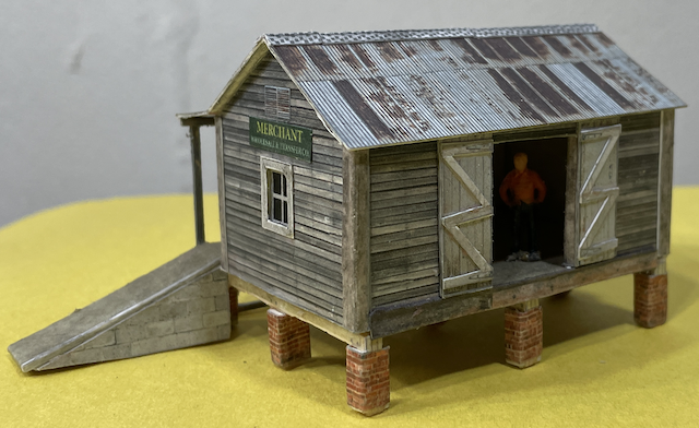
The signs were cut out and glued to each short wall over the windows. Even though I had used KRYLON Colormax Flat Crystal Clear spray paint on other buildings, a test piece of this building was made and sprayed. It worked fine. It was much better than the recommended matte varnish and didn't run or cause the colors to change. The whole structure had several coats of the Krylon flat applied. 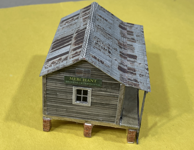 Once the finish had dried, several photos were taken. Two of the photos were shared on the Facebook Group titled, "Model Rail Buildings - Mostly Card & Paper".
|
