|
Flying High With Electric Power!
The Ampeer ON-LINE!
Fly the Future - Fly Electric! |
|---|
Site Table of Contents
| President: | Vice-President: | Secretary-Treasurer: |
| Ken Myers | Richard Utkan | Rick Sawicki |
| 1911 Bradshaw Ct. | 240 Cabinet | 5089 Ledgewood Ct. W. |
| Commerce Twp., MI 48390 | Milford, MI 48381 | Commerce Twp., MI 48382 |
| (248) 669-8124 | (248) 685-1705 | (2480 685-7056 |
 | ||
| Board of Directors: | Board of Directors: | Ampeer Editor |
| David Stacer | Arthur Deane | Ken Myers |
| 16575 Brooklane Blvd. | 21690 Bedford Dr. | 1911 Bradshaw Ct. |
| Northville, MI 48168 | Northville, MI 48167 | Commerce Twp., MI 48390 |
| (248) 924-2324 | (248) 348-2058 | (248) 669-8124 |
| The Next Meeting: Date: Saturday, October 3 Time: 10 a.m.
Place: Midwest RC Society 7 Mile Rd. Flying Field | ||
| Reminder About EFO Flying Season Meetings Ken shares that EFO Flying meeting dates are tentative. | Upcoming Midwest RC Society Swap Shop event announcement & details. |
| Dynam 50" WACO YMF-5 Gary Gullikson shares his views on this fine flying ARF. | Freewing Pandora Review & Some General RC 'Trainer' Thoughts, Part 2 Ken Myers continues his review of this plane and sharing thoughts in general on RC 'trainer' planes. |
| Regarding Fuselage Top Loading of the Battery from Robert Comerford shares his views on this topic. | Thank you Ken for your incredible part 1, "Selecting a Brushless Outrunner Motor Power System for Sport and Sport-Scale Airplanes" Article in the June 2015 Ampeer! Dave Peterson shares his thoughts on this article. |
| Denny Sumner's Omen III information on the maiden of this great flying Mark Rittinger design. | |
Dates given for the flying season EFO flying meetings are tentative. The date depends on the weather and may change from the one noted in the monthly Ampeer. The EFO Web site has the most current information posted. Also, emails are sent to EFO members if a date change is required. |
Midwest RC Society
location
admission charge
vendor table cost
For Information
directions
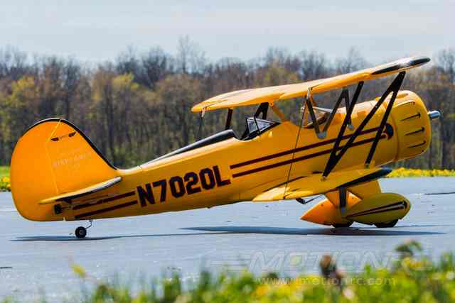
Return to "What's In This Issue" Dynam 50" WACO YMF-5
I read your review of the ARF trainer from Motion RC/China with interest. I just completed assembly and first flights of the Dynam 50" wingspan WACO YMF-5. I am not an experienced ARF assembler/modifier but am a veteran balsa model builder. After reading through the long, long thread in RCG Parkflyers forum, I ordered the WACO from Motion RC. The Dynam WACO airframe itself is a great flying model. The supplied components had some problems. The provided brushless motor is OK. The speed control is problematical and unreliable. The 40 amp "Detrum" speed control in the package is a "mystery" item. It is sold for $13.88 by another supplier and has timing issues resulting in uneven throttle up as well as frying in flight, etc. I could not tell from the label on the speed control whether it had a switch mode or linear BEC. The speed control instructions in the box were apparently copied from the instructions for the current Pentium and Guard series ESCs from another Chinese brand of speed control, Hobbywing (??). Motion RC told me that they were not provided this information but that nobody had any problems with the Detrum ESC. (Not so according to the thread in RC Groups) I e-mailed Dynam in China, but I never got a reply. I went ahead and used my 60 amp Cobra ESC with a 5 amp switch mode BEC. After installing my Hitec Optima receiver, I noted that the Detrum servo in the right wing was DOA (dead on arrival). I had to deal with that during assembly. I contacted Motion RC Support and asked for advice on removing the glued in servo. I was told to wiggle the servo and that it would eventually come out. It eventually came out, but a chunk of foam came with it making a hole through the top of the wing. I cut the foam chunk off of the dead servo and glued it back in place. Note: One of the posters on RCG cut around the servo with an X-acto and soaked the servo/glue with alcohol, which eventually softens the glue and allows for removal of servo without collateral damage. I glued a Hitec HS-55 in the cavity with clear silicon sealer. The steel cabane supports were crude stamped out parts with sharp ragged edges that had to be filed so as not to be dangerous. The cabane supports and 'N' struts also need to be painted yellow to match the rest of the model. The cabanes are not accurately bent to meet the fuselage and top wing attachment fittings. Getting them to mate with the fittings and centering the top wing was a tedious trial and error process. I ran into the same metric screw jargon, that you noted in your review, when trying to find the right machine and self-tapping screws. Attaching the cabane supports and N struts with the tiny short screws and nuts drove a number of fumble fingered assemblers (on RC Groups) bonkers and they replaced them with socket head screws and elastic nuts which required enlarging the holes in the attachment points. I happened to have a tiny 4mm wrench with box end. I put adhesive tape on one side of wrench and pushed the nut into the tape. I used the small magnetized Phillips screwdriver to grip the tiny screw while I drove it through the cabane support and N strut holes and through the attachment fittings and into the nut held by the wrench.�It went quite easily. I secured each tiny nut to its screw with a dab of CA. The plastic attachment fittings crumble if you get thread locker on them. I have had similar ESC and servo problems with the Parkzone Stinson Reliant. I won't go into my stuggles with the Maxford Gee Bee Model E. To sum up, the more complex ARF models are not for beginners. I am surprised that so many have limited success with all the foamy ARF warbirds. Gary Gullikson, Garden Grove, CA Freewing Pandora Review & Some General RC 'Trainer' Thoughts: Part 2
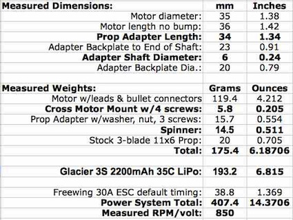
This is the continuation of Part 1. Part 1 appeared in the September 2015 issue of the Ampeer. The Freewing 3536-800Kv motor and Freewing 30-amp ESC were removed from the plane for bench testing and to gather the weights and measures. The following is averaged recorded data using the Emeter II logging function with the stock 3-blade 11x6 prop and a Glacier 3S1P 2200mAh 35C LiPo. The data was logged and averaged for three motor runs on the same pack, one after the other. 11.85V, 25.19A, 298.5W, 7942 RPM
11.75V, 24.68A, 290W, 7852 RPM
11.7V, 24.6A, 288W, 7839 RPM
Aircraft Assembly The plane was first assembled in the low-wing, conventional gear configuration. I later figured out that, to set the recommended CG (see Part 1), it should have been configured in the cabin, high-wing, conventional landing gear configuration first and then changed to the low-wing configuration. Following the illustration on page 18, of the very poor instruction manual, the plane went together very easily for me, but... With almost 60 years of aeromodeling under my belt, I have acquired a lot of useful tools. The supplied screwdriver is inadequate to assemble the plane. It will quickly round out the phillips type slots in the very soft metal screws, and it doesn't actually fit some of the screws. I had two screw drivers that worked perfectly. There is supposed to be a Freewing Pandora Hardware Parts Set available, which includes all of the screws, from Motion RC, but it is frequently unavailable. The supplied 2mm allen wrench is ONLY used for the bottom allen screw of the tailwheel assembly coupler. The 2mm allen screw on my example was difficult to loosen. Like the top tailwheel steering fitting, the wheel collars on the main conventional landing gear used 1.5mm set screws. The wing panel alignment holes did not align with the tabs with the threaded insert holes on the wing center sections. The wing panels could not be 'pushed in' far enough to align the holes. I used a carbide cutter, in a Dremel, to elongate the screw holes in the wing panels just slightly towards the center section. This problem was not unexpected. A Tactic TTX650 transmitter and Tactic TR624 receiver were used. A new airplane model, with the throttle channel reversed, was set up on the Tactic TTX650. ESCs require the throttle channel to be reversed on a Tactic transmitter. A charged 4-cell NiMH battery pack was used to link the TR624 receiver to the TTX650 transmitter and to power the receiver during radio system setup. The supplied "Y" aileron connector was plugged into the aileron socket on the receiver. The marked elevator and rudder servo plugs were plugged into the receiver. The elevator and rudder pushrods were NOT connected to the movable surfaces at this time. The ESC was not connected at this time. The NiMH battery pack was plugged into the receiver to 'center' the servos. The E/Z connector type screws were loosened for the elevator, rudder and tailwheel pushrods to slide freely. The clevises were attached to the outermost holes of the rudder and elevator surface control horns and the safety loops secured over the clevises. The elevator, rudder and tailwheel were adjusted to neutral by eyeball and E/Z type connector screws tightened. The Tactic TTX650 elevator and rudder movement was reversed for correct throw movement. 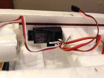 The Tactic TR624 receiver is held in place by Velcro on the right side of the fuselage. Using a 5" or 6" aileron extension, not supplied, or indicated as needed, plugged into the receiver aileron socket makes plugging and unplugging the "Y" aileron connector much easier when the wing configuration is changed. Inside the fuselage, the EPO foam was sawed and cut out that held the nose gear pushrod guide. This provided room for a 1/8" Lite ply battery tray extension. The battery tray extension was not glued in place until the Castle Creations Phoenix Edge 50-amp ESC was installed, using Velcro, in a position under the tray extension. The Cobra 2820/12 arrived on June 2. The weights and measures were taken. Five APC props were selected to gather data for Drive Calculator input. The prop selection was based on data from the Innov8tive Design's Website for this motor.
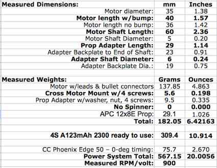
The Kv was measured and found to be about 901 RPM/volt. Oh, oh! The motor had a stated Kv of 970 RPM/volt. The motor was mounted for the bench test. The CC Edge 50-amp ESC was set to 0-deg timing (low). I always use 0-degree timing with my outrunners. The 'new' 4S A123 2300mAh pack was fully charge. The pack was made using 4 cells from a 28V DEWALT (8 cell) power pack, which I've had on hand since 2007 or 2008. Because of the lower than expected Kv, the initial and final prop used for flying was an APC 12x8E. The following is recorded data, using the Emeter II logging function, for an APC 12x8E prop and the 'new' 4S A123 2300mAh pack. The data was logged for three motor runs on the same pack, one after the other. 11.23V, 36.4A, 408.8W, 8211 RPM
11.00V, 34.9A, 383.9W, 8022 RPM
10.90V, 34.2A, 372.8W, 7996 RPM
The Cobra/A123 power system weight increased the ready to fly weight by 159.75 grams, or 5.64 ounces, over the stock version using the Glacier 2200mAh LiPo battery. That is a wing loading increase of 1.6 ounces per square foot and a wing cube loading factor of 0.85. Both are inconsequential to the plane's 'flyability'. The Low-Wing Conventional Gear (lightest weight - no tail weight included*) weighs 3.33 pounds ready to fly. Using 298.5 watts in (the best recorded average for the stock motor) yields 89.6 watts in per pound, but the watts out, using 71.4% efficiency, is 213. 213 estimated watts out yields 63.9 watts out per pound. The Low-Wing Conventional Gear with the Cobra power system, 4S A123 2300mAh pack and 1.25 ounce tail weight, weighs 3.82 pounds. Using 408.8 watts in (the best recorded for the Cobra motor) yields 107 watts in per pound, the watts out, using 77.4% efficiency, is 316.4. 316.4 estimated watts out yields 82.8 watts out per pound. Another important performance predictor is the estimated stall speed to pitch speed ratio. The Low-wing Conventional gear's stock power system estimated stall speed is 14.4 mph and pitch speed is 45 mph. 45 mph divided by 14.4 mph = 3.125 (Keith Shaw, "To do clean inside loops, rolls, and other sport-type aerobatics, three times stall speed is needed.") The Low-Wing Conventional Gear with the Cobra/A123 power system estimated stall speed is 15.4 mph and the pitch speed is 62 mph. 62 mph divided by 15.4 mph = 4.036 (Keith Shaw, "Anything over 4 times the stall speed gives 'fighter-type' performance and extended vertical aerobatics.") Both of the performance indicators illustrate that the stock power system should provide okay performance for this type of plane and the Cobra/4S A123 power system should provide much better performance. I never flew the plane with the stock power system and 3S LiPo, because I do not use LiPo batteries, but the videos on the Motion RC Website certainly indicate okay performance. The conventional gear, low-wing configuration, with no tail weight, was used for the first five flights. There were absolutely no bad flying habits exhibited. The power was more than adequate. There was no indication of a 'nose heavy' condition. Except for vertical maneuvers, the throttle stick position on the transmitter seldom went slightly above the 1/2 stick position. Two flights were flown using the cabin, high-wing configuration with no tail weight. The only noticeable difference between the two configurations was in the roll, as might be expected. The last half of the roll, from inverted to upright, was much quicker than the first half of the roll, from upright to inverted, for the cabin, high-wing configuration. The low-wing configuration rolls were a bit more axial. Five flights were flown using the cabin, high-wing configuration with 1.25 ounces of tail-weight added. The 'feel' was much better and the landings could be 'floated in' slower. Almost no forward pressure was required to hold the plane in inverted flight. Keith Shaw flew one of the five flights with the added tail weight and put the Pandora through a highly aerobatic routine including 4-point and 8-point rolls, loops (inside and outside), snaps (rights, lefts and inverted - it really doesn't snap roll well - good for a trainer), spins (which it doesn't like to do) and many other maneuvers that no pilots in training should fly, but could advance to. The plane has a tendency to bounce on landing with the stock, very, very firm, EPO foam wheels. Even Keith bounced a few landings, while doing touch and goes, before finessing it in. Part of that bounce might also be due to the non-linear feel of the elevator. It appeared that the non-linear feel was due to 'buckling', under load, of the extremely thin elevator pushrod wire. 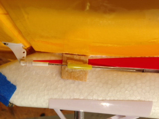 A small, triangular wedge shaped shim, when viewed from the top, was sanded from a small piece of 3/32" balsa. It was attached to the side of the fuselage with medium CA and CA 'kicker'. A piece of inner NyRod was slipped down the thin elevator wire. CA and baking soda was used to hold the guide/holder NyRod in place to minimize the buckling. The stock EPO foam wheels were changed to Dave Brown Products #709471057352 Lite Flite WR35-5735 3-1/2 IN FLITE (TRD) wheels from Flightline Hobbies. The wheel change added 57g, about 2 ounces, to the plane, but the 1/2 oz. of tail weight could be taped to the slant on the rear end of the fuselage to maintain the correct CG. The final flying weight, for my high-wing, conventional gear version, was 64 oz., 4 lb. or 1815g. The wing area loading is 18 oz./sq.ft. and the wing cube loading factor is still a very flyable 9.58. Changing the wheels only slightly reduced the bouncing tendency. I just need to learn the 'best' landing procedure for this plane and teach it to my students. If I had it to do over, I'd not silicone around the main landing gear wire inside the wheel fairings and not change the wheels. Unfortunately, the main landing gear are not set wide enough apart to keep the plane from tipping to the side when taxiing out for take off or back to the flight line after landing. The plane exhibits a very nice flying characteristic that I've never found on any other flat-bottom airfoil planes that I've ever flown. If the plane is trimmed to cruise around at a moderately slow 'instruction' speed of about 1/2 the throttle stick position and the throttle stick is pushed to the maximum, the plane barely starts to rise in a climb. It's actually pretty amazing, and a really nice characteristic. Overall the plane can be a very docile flyer, and handles some wind, say up to about 10 mph, pretty well. Every EPO foam 'trainer', that I've seen, is white with some spiffy self-stick graphics on it. In the air, they still appear basically white. White airplanes do not present well for orientation purposes in gray skies or even when a lot of clouds are present. Some beginners to the hobby tend to paint their trainers to make them look a bit better and different. Most of them don't think about visibility for orientation. I have found that shiny Cub yellow on the wings and the horizontal stabilizer/elevator work well for visible orientation on cloudy days. I'm often 'ribbed' at the field for my plethora of Cub yellow winged aircraft with red fuselages, but they 'work' best for me, and my vision, in all light conditions. After flying five flights in one day with totally 'gray' skies, and losing orientation more than a few times, I decided it was time to cover the wings and horizontal stabilizer/elevator with Cub yellow Top Flite EconoKote. I did nothing to prepare the EPO foam surfaces, except for wiping them down with a clean, dry cloth. The EconoKote was ironed on using a Coverite covering iron covered with a sock on it. The iron/sock combination was set to 205-deg F, the temperature recommended to activate the adhesive, using an infrared thermometer.
There is a slight, very slight, alligator texturing caused by the heat 'bring up' the foam beads in the EPO foam. The self-stick graphics were reapplied. The wing panels were done in the same fashion followed by the cabin, high-wing center section assembly. The EconoKoted parts were weighed and compared to the original weights.
The total weight increase, due to the EconoKote, was 58.25g or 2.05 ounces, but... Most of the covering weight was actually added behind the CG. Instead of 1.25 ounces of lead added to the tail, only 0.5 ounces was required. That means that the actual increase, to the ready to fly weight, was only about 1.3 ounces/36.9g.  1.3 ounces is a very small weight penalty to pay for much improved visibility in all lighting conditions. The plane flies as well as ever and is much easier to keep oriented. I recently buddy boxed several Cub Scouts on this plane and my Sensei. There was an extremely heavy cloud cover that evening. The non-RC flying parents could easily see that the 'yellow wing plane' was much easier to see, and follow, than the 'white wing plane'. Motion RC states, "The Freewing Pandora is not only one of the best beginner planes on the market, it is a great intermediate plane too." If by beginner plane, Motion RC means that it is relatively easy to fly, with no bad flight characteristics, I agree. Set up as the cabin, high-wing taildragger, it can be a good trainer on a grass RC club flying field with a flight instructor. It is NOT a beginner plane to take to the local park and try to teach yourself to fly on your own. The elevator is too sensitive. The ailerons would have been a bit too effective for training, if the throw had not been reduced by moving the pushrod into the second from outer hole on the servo arm and connected to the outer hole in the aileron control horn. The sport pilot should really like this plane. It is fun to fly, does sport maneuvers quite well, and with its four-in-one, unique design, it is certainly different. Changing out the stock 30-amp ESC for a 40-amp or 45-amp ESC and running a 4S LiPo could certainly add some 'pep' to it. Set up this way, the sport flyer should really enjoy the flying capability of this plane, as well as its uniqueness. Motion RC is now offering a 35-amp ESC as an upgrade for this plane. Using the stock motor, stock 3-blade prop and stock ESC, with a 3S LiPo, the amp draw is about 25 amps near the beginning of the pack run. When using the stock motor and stock 3-blade prop with a 4S LiPo, the anticipated amp draw should be in the mid to high 30 amp range. I believe a 45-amp or 50-amp ESC would be most appropriate, IF the stock prop is to be used. Of course the amp draw could be 'lowered' using a 2-blade APC 11x5.5E, or an APC 10x8 sport prop for greater speed. The modified Freewing Pandora has worked out okay as a trainer and it is fun to fly. If I had it to over again, I'd go with the Multiplex Mentor. I'd choose my own Hitec servos and power system. Because the Mentor is more like a traditional 'kit', it would be easier to add color for orientation purposes, either Top Flite Econokote or paint, before final assembly. The Mentor also has a wider main gear for better ground handling. You shouldn't be too surprised if a Multiplex Mentor review turns up in a future Ampeer, as my quest for a better 'club' trainer continues. Regarding Fuselage Top Loading of the Battery
Hi Ken, I just read you latest [September 2015 Ampeer issue]. Many thanks again. I am amazed at the planes that do not have top loading hatches these days. I am going to modify my HK WOT4 clone soon. I get tired of turning it upside down to change packs. My flying mate has noted the 2100mAh LiFe soft packs are starting to bloat even though they have been used well within the advertised limits for charge/discharge. Have fun,
Thank you Ken for your incredible part 1, "Selecting a Brushless Outrunner Motor Power System for Sport and Sport-Scale Airplanes" Article in the June 2015 Ampeer!
Hi Ken, Wow! I cannot thank you enough for your article you wrote in this issue of the Ampeer titled: Selecting a Brushless Outrunner Motor Power System for Sport and Sport-Scale Airplanes (Part 1) By Ken Myers. Ken, this is some of the best info I have ever seen on electric motor selection. I can hardly wait until the 2nd issue. To see the rest of the story, but thank you so much for the many hours of work, calculations and information you shared with us all. This hits close to home to me, as you know I have a Slow Poke .15 to .25 that was converted to electric by someone with limited knowledge. I took all the actual data that I could gather to make it fly based on the 35Amp ESC chosen, the prop size of 12x6 APC electric that was on it, and even the unknown motor specs, and chose the battery selection that should have been more than adequate, using the eCalc calculator of course to verify the info I had. I have an inline WattsUp Watt Meter that measure all parameters and by taxi the airplane weighing in at 4 lbs 4 ounces, the max current was below or at 30 amps, etc. All looked great! So I take it to the field and fly it. Hoping for the best. The taxi was fine, the takeoff sluggish but manageable, and the plane flew great around the field one pass. Then on to the 2nd pass, all of a sudden, the plane spiraled into a death dive for no reason at all. I had slowed down the throttle just a bit to be sure not to over tax the system but it just quit, and my belief is the ESC shut down due to excessive current. I also had a power data logger onboard, it is the DPR-50 that was offered a few years ago that captures P, I, V, and mAhs used. I had to go back twice to search for the plane in high thickets. But success! And guess what? There was not a scratch on the plane except about a 1 inch small tear in the wing Monokote. Now, in all my years flying, I have never ever had a break like this one! Truly amazing how it bounced around in the thicket to a smooth and safe intact plane! I know I got lucky. I only share this story to reinforce what you have written was invaluable to me and to many. I have 40 years of Electronics and Engineering experience, as well as computer experience, and flew on an AMA Sanctioned show team. What worked is the glow engine size rating to the kit. What does not work well yet, IMHO or lack of skills and knowledge, is the ability to even pick the right power system for any kind of plane that is not an ARF with BNF add battery and go, it seems. I am not complaining, but I can bet if I looked closer at the weight of the Slow-Poke, and realized from your article that if the plane was 4 lbs and 4 ounces then I would need more power and more battery. What would be wonderful to see happen in this hobby is some way to better estimate the real life power systems needed easier for the average RC pilot (I fly everything except drones and jets, including heli's I fly as well)... I would love to convert some of my older planes to electric if possible. Ideally taking the perspective of your 1st article on this subject by including all the parameters and how to narrow it down will be so very helpful. There needs to be an easier way to do this, and so far your 1st article makes it look like that may be possible. I have to tell you though, your knowledge and skill level on the topic thus far will be far greater than anyone with experience like me, and for those who are not EE's or experienced with the formula's etc it will still be difficult at best to still figure it out without some help. Congrats on a great article, I am not going to pursue further the Slow Poke conversion, as I prefer a more stable 4 channel plane than rudder and elevator, on a .15 to .20 size plane. I like more sporty, aerobatic planes in the .45 to .91 range that have a punch, something maybe my electric dreams will limit based on cost and power required. They may just stay nitro for now for those reasons. Again, just sharing some real world examples that I think will be great if you can somehow work these into part 2 of the article next month for all of us out here trying to figure it out. You are just the best Ken, many thanks for taking the time to read this, and any comments appreciated. Thank you for all you do for the electric world, it's a place I want to move to, but shared with you my experiences and concerns. Thanks again, I hope this helps give you a real life example and again my sincere thanks for all you do for the hobby! I admire you so much! Sincerely, Thanks, Dave PS - I am also an Advanced Class Amateur Radio Operator WA4EPW, and 40 years of circuit board building, computer building and electrical engineering experiences, as well as a past AMA Sponsored Show Team Pilot, with pattern, sport, aerobatic, acrobatic RC planes of all sorts. As well as multiple heli's too.
Denny Sumner's Omen III
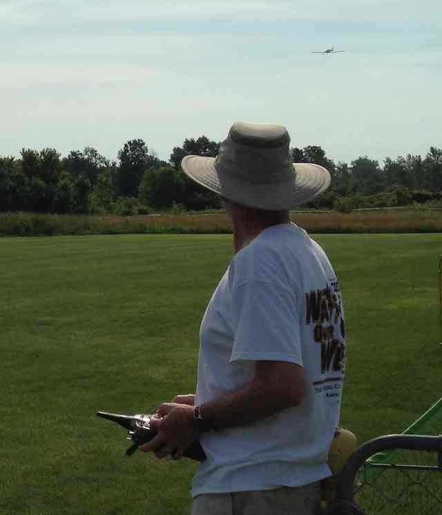
The photo shows Denny Sumner landing his Mark Rittinger designed Omen III after a very successful maiden flight. Denny described the flight in a very short sentence. "It flew smooth, like butter!" Mark based his Omen III design on the Omen II, by Don Wilkes. Don's design spanned 92". Mark simplified the original 1968 design and dropped the span to 65". The plans for the Omen III are available from Model Airplane News. Mark's build thread on RC Groups The thread also contains more information on Denny's prototype serial number 2. Denny's version weighs 5 pounds even. The E-flite Power 46 turns a 12x8 prop using a 4S 5300mAh LiPo. It pulls 35 amps, which provides 545 watts in for 109w/lb. He put 6 great flights on it on the first day. 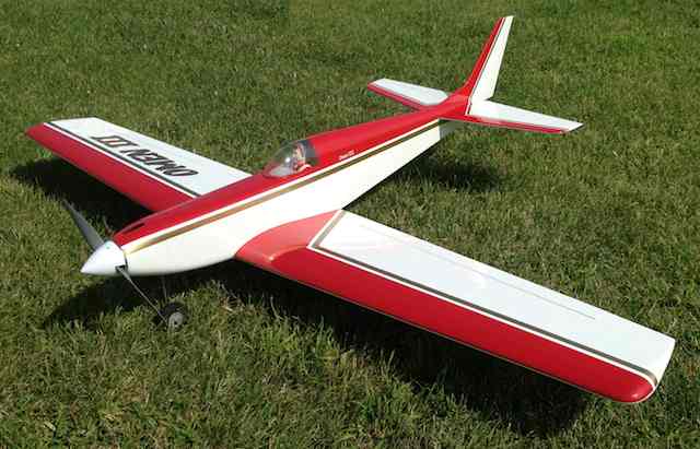
Denny Sumner's, Rittinger designed Omen III Pattern Plane Return to "What's In This Issue" To Reach Ken Myers, you can land mail to the address at the top of the page. My E-mail address is: KMyersEFO@theampeer.org |