1. The Problem:

Coupler Housings Painted Preparing to Remove the Body Shell From the Chassis on the 2nd Loco
I made three loops of masking tape with the sticky side out. I stuck the loops to the plastic and flattened them out. The screws and coupler parts were stuck to the tape for safe keeping. Once the paint had dried, I used a number 0 phillips head screwdriver to unscrew the coupler and its housing from the chassis. An X-ACTO knife, with a #11 blade, was used to split the paint between the two sides of the coupler boxes before the coupler parts were removed. Each set of coupler parts was placed on individual loops of masking tape to keep the same assemblies together. I removed the four screws that held the body shell to the chassis and placed them on the third piece of tape.
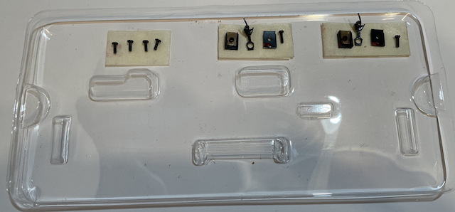
The photo shows the screws on the second locomotive's box plastic cover, but the plastic from the train set could also be used. I set the parts aside and carefully removed the body. The front LED is in the body, but neither example of this locomotive had their LEDs glued in. They were easily removed and the body shell set aside. 2. The Problem:
WARNING! ABSOLUTELY AVOID TOUCHING THE SPEAKER DIAPHRAGM DURING THE FITMENT AND INSTALLATION PROCESS. The Solution to #2 was archived here because using a Li-Po no longer applies. 3. The Problem:
The Solution to #3 was archived here because using a Li-Po no longer applies. 4. The Problem:
Preparing the Chassis for Dead Rail Operation On the original CSX chassis, I did not know how easily the track power pick-ups could be removed, since they are not required for battery operation. To remove the track power pick-ups, note the orientation of the removable sides of the truck assemblies.
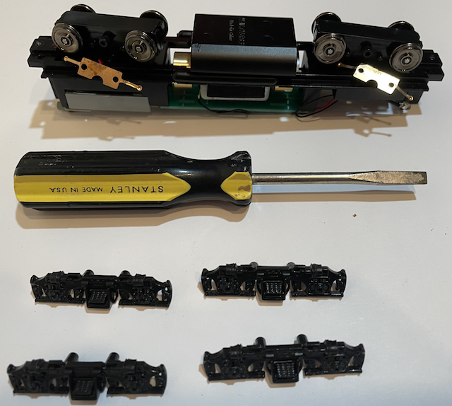
Truck Side Piece Assembly Removal With a small, but not tiny, flat-blade screwdriver, gently wiggle and pry the four side assemblies loose from the trucks and set them aside. Snip the wires off of the wheel pick-ups. The front pick-up wires can easily be brought up through the frame. The rear pick-up wires are under a gray colored plastic box.
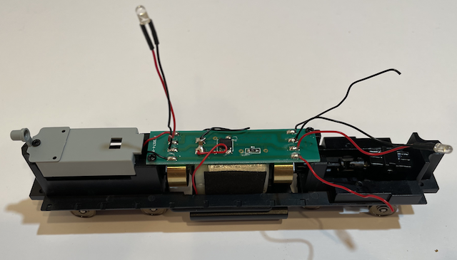
The gray box and rear light bracket For the CSX conversion, with the LiPo in the body shell, the gray box needed to be removed and the part of the box, where the screw went through it, needed to be cut off the gray box to act as a washer. On the conversion of the second Conrail, the gray box was left in place. Thus, making a washer, as described next, was not necessaary.
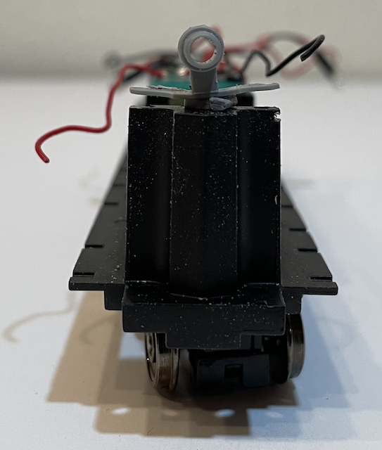
Washer under rear light bracket was cut from the gray box Unscrew the rear light bracket. Remove the part of the rear light bracket behind the screw hole. Remove the round protrusion on the gray box to act as a washer. Reassemble the now shortened rear light bracket by inserting the screw through the bracket and the washer part, that was cut from the gray box.
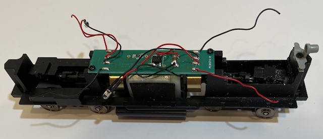 The chassis now looks like the photo above before the PCB was removed. Reassemble the side assemblies to the trucks. Unsolder all of the wires from the printed circuit board (PCB). Put the extra wire pieces and the two screws in a container for possible future use and discard the PCB. Only the motor wires are left on the chassis connected to the motor. 5. The Problem:
At first it appeared that the locomotive, box car and gondola did not have a consistant problem anywhere on the layout, but after more test runs, the gondola did have a derailing issue.
I created a tool to find out how much the caboose should weigh according to NMRA recommended practices for HO scale. The tool in PDF format for downloading.
 According to the guide, the caboose should weigh 3.5 oz. or about 99 grams. It only weighed 2.18 oz. or 61.9g as delivered. According to the NMRA recommendation, it needs about 1.3 oz. or 37g of weight added. The caboose shell was carefully removed from its chassis.
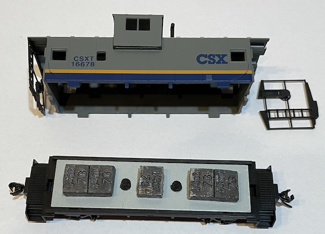 The shell was reinstalled on the chassis. The caboose with the added weight weighs 3.52 oz. or 99.7g It appeared to track better with no derailing. 6. The Problem:
According to the tool, the approximately 7" gondola should weigh 4.5 oz. or about 127.6 grams. It needs about 2 oz. or 56.7g of weight added. The gondola is the battery car for the second conversion, therefore the two AAA battery holders and 4 Lithium-ion 10440 350mAh batteries were placed in the gondola.
It did track better with no derailing. |
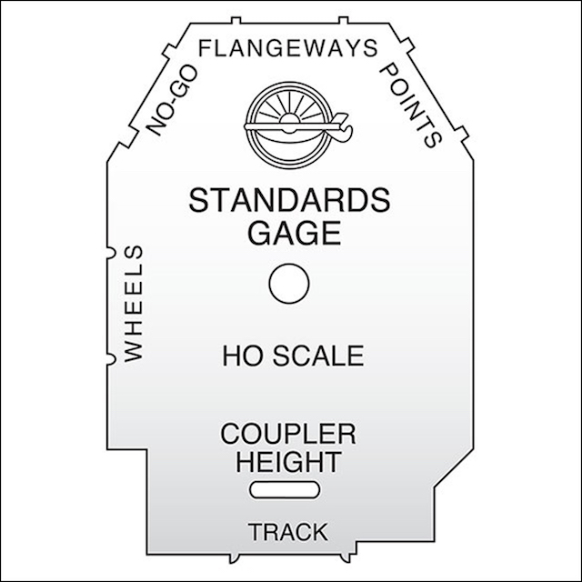 I no longer had an NMRA gauge to check the wheel sets' gauge.