|
Flying High With Electric Power!
The Ampeer ON-LINE!
Fly the Future - Fly Electric! |
|---|
Site Table of Contents
| President: | Vice-President: | Secretary-Treasurer: |
| Ken Myers | Richard Utkan | Rick Sawicki |
| 1911 Bradshaw Ct. | 240 Cabinet | 5089 Ledgewood Ct. W. |
| Commerce Twp., MI 48390 | Milford, MI 48381 | Commerce Twp., MI 48382 |
| (248) 669-8124 | (248) 685-1705 | (2480 685-7056 |
 | ||
| Board of Directors: | Board of Directors: | Ampeer Editor |
| David Stacer | Arthur Deane | Ken Myers |
| 16575 Brooklane Blvd. | 21690 Bedford Dr. | 1911 Bradshaw Ct. |
| Northville, MI 48168 | Northville, MI 48167 | Commerce Twp., MI 48390 |
| (248) 924-2324 | (248) 348-2058 | (248) 669-8124 |
| The Next Meeting: Date: Saturday, October 31 Time: 10 a.m.
Place: Midwest RC Society 7 Mile Rd. Flying Field | ||
| Reminder About EFO Flying Season Meetings Ken shares that EFO Flying meeting dates are tentative. | Upcoming Midwest RC Society Swap Shop event announcement & details. |
| What Happens to the Amp Draw if a Cell is Added to a Battery Pack and the Same Motor, Prop, and ESC Are Used? Ken Myers shares his research on this topic. | More on the Dynam Waco Gary Gullikson shares more information on this nice flying ARF. |
| Skymasters Indoor Flying at Ultimate Soccer Arenas Dates, times and cost for the indoor flying season at Ultimate Soccer. | Vista Power Quadplay Q3620 update, Maxford Gee Bee E/Y & Sig 1/6 scale Cub Gary Gullikson shares more information on these items. |
| Maxford Gee Bee Flying Update Gary Gullikson shares flying info on his Maxford Gee Bee. | |
Dates given for the flying season EFO flying meetings are tentative. The date depends on the weather and may change from the one noted in the monthly Ampeer. The EFO Web site has the most current information posted. Also, emails are sent to EFO members if a date change is required. |
Midwest RC Society
location
admission charge
vendor table cost
For Information
directions
Return to "What's In This Issue" What Happens to the Amp Draw if a Cell is Added to a Battery Pack and the Same Motor, Prop, and ESC Are Used?
Bert and Ernie are at the flying field. Bert just landed his new little Zoomer after a successful maiden. "Hey Ernie, what did you think about that flight? I thought it was a little too slow," said Bert. "It looked fine to me. What ya got in it for power?" asked Ernie. "It is a Cobra C-2208/26 turning an APC 7x5E. I'm using a Castle Creations Thunderbird 9-amp ESC and a 2S 600mAh LiPo battery," replied Bert. "I've got a 3S 1000mAh LiPo with me. Do you think I ought to try it?" After a moment of consideration, Ernie said, "If you are going to go up by a cell, you should really decrease your prop diameter, and maybe the pitch, to keep within the safe operating limits of your ESC and motor. How many amps are you drawing on that 2S pack with the 7x5? Do you have a smaller prop with you?" "Don't know how many amps. I never checked it. I didn't bring a smaller prop with me either," noted Bert. "I think I'll just use that 3S 1000mAh pack. I'm really feeling the need for speed today." At the other end of the field, Bud just landed his sport plane and taxied back after a successful maiden flight. "Hey Lou, what did you think about that flight? I didn't think I had quite enough power," said Bud. "It looked fine to me. What ya got in it for power?" asked Lou. "It is a Cobra C-4130/20 turning an APC 15x10E. I'm using a Castle Creations Edge 75-amp ESC and a 9S 5000mAh LiPo battery made up of three 3S 5000 packs in series," replied Bert. "I've got a 4S 5000mAh LiPo with me. Do you think I ought to try it in place of one of the 3S packs?" After a moment of consideration, Lou said, "If you are going to go up by a cell, shouldn't you really decrease your prop diameter, and maybe the pitch, to keep within the safe operating limits of your ESC and motor. How many amps are you drawing on that 9S pack with the 15x10? Do you have a smaller prop with you?" "If I remember correctly, it was somewhere around 45 amps. Unfortunately, I didn't bring a smaller prop with me," noted Bert. "I think I'll just replace one of the the 3S 5000 packs with the 4S 5000mAh pack to make it a 10S pack. I'm really feeling the need for a bit more power today." What was the most likely outcome of the day for Bert and Bud? Ron van Sommeren, of the Netherlands, is a 'for real' motor EXPERT on RC Groups. In just one of his many posts about adding a cell to the power system, he noted that "Motor-current is proportional to voltage squared (2) and proportional to Kv cubed (3). This is worst case, because battery voltage will decrease/sag a bit due to more current and voltage losses in the motor will be higher too." Ron explains why this should be true here. Actually, it became clearer to me when I thought of the proportional voltage increase, as the new expected voltage divided by the original voltage, its ratio, which was then squared. The following is an example of going from 3 to 4 cells. Example: Going from a 3S pack to a 4S pack the amp draw increase, using Ron's formula, would be (4/3)2.
A 3S pack's voltage under load might be 11.1V. A 4S pack's voltage under load might be 14.8V. Both voltages are based on 3.7 volts per cell under load.
According to Ron, going from a 3S pack to a 4S pack increases the amperage by a factor of 1.7777778. The noted factor in his table is 1.8. He rounded 1.77777778 to the nearest tenth. Example:
Bert's Cobra 46.5g C-2208/26 at 7.4V (2S pack) with an APC 7x5E pulls 8.56 amps. That is pretty close to the maximum rating for his 9-amp ESC. On the same Innov8tive Designs' Web page, an 11.1V (3S pack) with an APC 7x5E is shown to pull 14.93 amps. According to Ron's formula for going up from a 2S pack to a 3S pack;
That is a 4.33 amp difference between the Innov8tive Designs' measured data, 14.93 amps, and Ron's predicted amp draw, 19.26 amps. Why? Bud's 396g Cobra C-4130/20 at 33.3V (9S pack providing 3.7 volts per cell under load) with an APC 15x10E pulls about 45 amps. A 37V (10S pack) with an APC 15x10E is shown to pull 53.62 amps. According to Ron's formula for going to a 10S pack;
That is only a 1.995 amp difference from the measured amp draw. That appears to be a closer estimate. Why? Why is one prediction 'quite a bit off' and the other apparently much closer? After looking at more examples from the Innov8tive Designs' Web site for Cobra Airplane Motors and comparing the results of the measured amperage increase with the results from Drive Calculator, it appeared that Ron's formula was over-estimating the amperage increase. I posted this observation, and my supporting data, on August 8, 2015 on RC Groups. My post proved to be only 'partially' correct. I had only begun to examine what was going on at that time and didn't have enough data collected for a wide range of motor weights and brands. These early observations turned into a two month long project of gathering comparative data for ALL of the Cobra and Scorpion Motors and a few of the AXI motors. The results are posted in an Excel workbook of spreadsheets. Ron's method of prediction is safe for sure, but... Why does the voltage or cell count high divided by (/) the voltage or cell count low and then squared (^2) always produce, what I consider, an unacceptable amp increase prediction? The amp increase prediction is based on RPM, which is based on the final output voltage after all of the voltage drops through the system. It is not based on the input voltage at the ESC, which we can measure with a power meter. RPM is the final, or output, voltage times the Kv. It is NOT the input voltage times the Kv. Therefore the high RPM divided by the low RPM gives the same ratio as the high final output voltage divided by the low final output voltage. The following example is in the workbook on the spreadsheet named Proofs. Drive Calculator was used to provide the data. It is not 100% accurate, but good enough for this purpose.
This process cannot be used to obtain an estimate. It has an unknown variable, the high RPM. Using the input voltages (AKA number of cells) with Ron's formula results in a larger margin of error in the estimate.
That appears to be quite a large over estimate, safe, but large. After a month of gathering actual, measured data for Cobra, Scorpion and AXI motors, new factors were created for estimating the amp increase when a cell is added to a battery pack. The table shows both Ron's and the new factors. The 1 cell to 2 cell factor has been dropped from Ron's table, as it is a very unusual configuration change. 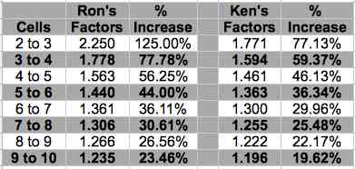 Note that the Factors, and % increase, of the collected data has shifted up approximately one ratio change. For example, Ron's 3 to 4 cell change, 1.778 and 77.78%, closely matches the collected data 2 to 3 cell change, 1.771 and 77.13%. Using the collected data factor for going from 3 to 4 cells in the previous example;
The new estimate is off by 30.1 amps - 28.4 amps = 1.7 amps 1.7 amps / 28.4 amps = 0.06 (rounded) = 0.06 * 100 for a 6% over estimate Using the collected data factor still produced a predicted over amp estimate, in this case, but it is a bit closer. There are a lot of variables that make trying to use input voltage or cell count imprecise. Some of these variables have been taken into consideration with the collected data factors, and some just can't be adjusted for. The PA Thrust 20 example produced one of the highest percent increase errors using the collected data factor of 1.594 for going from 3 to 4 cells. More of these examples are shown on the Proof spreadsheet in the Excel workbook. Bert's Cobra C-2208/26 at 7.4V (2S pack) with an APC 7x5E pulls 8.56 amps, according to the Innov8tive Designs' measured data.
According to Ron's formula, the estimate would be 19.26 amps, or over by 4.33 amps.
As a double check, Drive Calculator data was used and predicted 14.9 amps. Bud's Cobra C-4130/20 at 33.3V (9S pack) with an APC 15x10E pulls 45 amps. This is a 9S to 10S change. The collected data factor, shown in the table, is 1.196. 45 amps * 1.196 (new factor) = 53.82 amps On Innov8tive Designs' Web page, a 37V (10S pack) with an APC 15x10E is shown to pull 53.62 amps.
Ron's formula estimated 55.575 amps, which is over by about 2 amps. That really is not too bad but...
That is not a 'bad' margin of error for an estimate. The review of the Freewing Pandora, in the September and October 2015 Ampeers, noted that the folks at Motion RC said that a 4S LiPo could be used with the stock motor, ESC and prop instead of the recommended 3S LiPo. Using Drive Calculator, and the information gathered during the original 3S bench test, the estimate, using the collected data factor of 1.594, going from a 3S to a 4S pack was;
Ron's formula resulted in an estimate of 43.9 amps (rounded).
Based on the previous amp draw predictions for a 4S LiPo pack, it was with a bit of trepidation that I decided to test, and possibly sacrifice, the stock power system from the Freewing Pandora using a 4S LiPo pack. Pete Foss loaned me a Turnigy nano-tech 4S 3000mAh/3.0Ah 25C-50C LiPo battery. He noted that it was 'old' and somewhat "worn out". The stock Freewing 3536 800Kv motor, the stock Freewing 30-amp ESC and stock Freewing 3-blade 11x6 prop was set up for bench testing using Pete's 4S pack. An Emeter II was used to log the data. The temperature in the basement was approximately 65o Fahrenheit. Pete's freshly charged 4S was used to log 3 sets of data for a duration of approximately 10 seconds each, one after the other. The averages, as the pack ran down, were;
The highest instantaneous voltage and amperage recorded in the first run was 14.56 volts and 35.1 amps. With the pack fully recharged, the second run data was;
The highest instantaneous voltage and amperage recorded in the first run was 14.77 volts, or 3.69 volts per cell, and 36.1 amps. This was well below the 15.64 volts used in the estimation. The average voltage for the 6 data loggings was 14.15 volts, 3.54 per cell, and the average amp draw was 33.3 amps. The cells that make up a battery have an internal impedance. It is not easy to measure the actual internal impedance, and the result is not really useful for the end user of a battery. The equivalent series resistance (ESR) of a battery can be a more useful to the end user. The ESR of the battery is a calculated, not measured, value and the result is expressed in ohms, or milliohms. In common usage, it is stated as the battery's internal resistance (IR). With the proper equipment, a cell's IR may also be calculated. Unlike a true ohmic resistance, a cell's calculated IR, and therefore the battery's ESR, DECREASES as the temperature rises. What this means is that temperature changes have a large affect on a battery's performance. The ESR for Pete's 4S pack was approximately 2.5 times higher than the 3S pack. Not surprisingly, the new Glacier 3S was a 'better' pack than the old nano-tech 4S. The pack's varying Equivalent Series Resistance (ESR), due to heating, is one of the previously noted variables that cannot really be accounted for with simple factor formulas. When a cell is added to a pack, the pack's resistance goes up slightly, as the pack's resistance is the sum of its cell resistances. As the capacity of the cells used in the pack increases, in more instances than not, the pack's internal resistance decreases. Not all cells are created equal. For example, one 2200mAh pack may have a higher, or lower, ESR than another 2200mAh pack at the same temperature. A higher "C" rated pack SHOULD have a lower internal resistance than a similar capacity pack with a lower "C" rating. John Julian put it very well on RC Groups.
For more information regarding how temperature affects voltage and current delivery, see the May 2007 Ampeer. The article is "Lithium Face Off: A Head-to-Head Comparison of Li-Po, M1/A123 & Emoli" and the section is "A Warming Trend?". It is those 'darn' variables, again! The Multiplex Extra 300S is also known as the Hitec Weekender Extra 300S, when sold in the USA. I reviewed it and commented on it in the July 2014 and September 2014 Ampeers. Multiplex recommends a 4S LiPo battery and Hitec recommends either a 4S LiPo battery OR a 3S LiPo battery. On September 1, 2015, RC Groups member LedZepplin posted, "I have 12 flights with stock motor/ESC, 4s lipo and 13x8x2 prop. It pulls about 630 watts." The statement is inaccurate, but the numbers can be used. Drive Calculator data for the Hitec D3720-630Kv and an APC 13x8E:
On September 6, RC Groups member ablair asked, "Led have you tried a 3s battery with the 13x8 prop?" To reverse from a 4S pack to a 3S pack, use the factor, from the table, as a divisor. That means divided instead of multiply. On September 6, LedZipplin responded, "I measure about 290 watts and 6500 rpm with APC 13x8x2E prop." 39.6A / 1.594 (calculated factor) = 24.8A (rounded) for the estimate with a 3S pack.
That's close enough for me. To this day, the beginning of October, 2015, there is still NO amp draw data, on the Internet, for the stock motor, ESC and prop used with either a 3S or 4S LiPo battery. Weird. Lucien Miller, Mr. Innov8tive Designs, provided only one 6S (22.2V) to 7S (25.9V) example on his Web site for Scorpion and Cobra Airplane motors. The only 7S data on the site is for the Scorpion SII-4025-440. For the larger Cobra Airplane motors, he jumped from 6S (22.2V) to 8S (29.6V) and from 8S (29.6V) to 10S (37V). It is important to remember that Lucien used a power supply, not batteries to create his tables. Using 6S to 8S and 8S to 10S saved him a bit of 'work' and a lot of time, but it also makes sense. Going from a 6S to 8S pack gives an amp draw rise that is approximately the same percentage increase as going from a 3S to 4S pack, but just slightly higher. Moving up from an 8S to a 10S pack, the expected amp draw increase is approximately the same percentage as going from a 4S to 5S. Bud's stated amp draw, in the story, was based on an estimation created by Drive Calculator for that motor using 33.3V and the new factor.
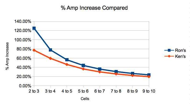 The graph demonstrates why both Ron's factor for the 9S to 10S change and the new factor for the 9S to 10S change are close in their estimations. Ron noted that his formula, and the resulting chart, are based on a lossless power system and does not take into account the higher losses due to the increased amp draw. It also does not take into account the differences in the ESR of the two batteries. So, how did Bert's and Bud's battery changes work out for them? What do you think? I'd love to hear from you. More on the Dynam Waco
I liked your inclusion of my experiences in assembling the Dynam WACO in the October 2015 Ampeer. I would like to add that once you get it assembled properly and paint the cabane and N struts yellow, to match the rest of the model, it looks great and flies wonderfully. It does all of the basic aerobatics including outside loops and many maneuvers I don't have names for. It is easier than many tail dragger, high wing scale models to take-off and land. I added "rigging wires" to wings and tail feathers using attachment points made from iron wire pushed trough foam, ends bent back and glued, so as not to pull out of foam. For rigging wires I used stretchy chrome beading cord from the craft store. Eventually it will go slack and be replaced with non-stretch fishing line and small springs for light tensioning. Too tight can warp wings, etc. It is a great flying, scale foamy, but I will keep watch on Detrum servos. I am using 4S 3000mAh Admiral LiPo packs and the stock 12x6 prop. It gives plenty of power and about 9 minutes of safe duration with aerobatics. The battery is set forward in the battery compartment about to enter the hole in the foam in my model. I have also used the smaller 2200mAh Admiral LiPo centered in the battery compartment. I plan to add some washers to give a little motor down thrust. The model wants to climb excessively at 3/4 to full throttle. The model scoots right along at full throttle. BTW (by the way) I have a 1/6 scale Williams Bros pilot bust with balsa extension in rear cockpit. Your WACO's CG may vary. Gary Gullikson, Garden Grove, CA Skymasters Indoor Flying at Ultimate Soccer Arenas, 867 South Blvd., Pontiac
We have some great news to share. Ultimate Soccer Arenas has extended our flying time by 50% for all 26 flying sessions this season. Each day we will be starting at 10AM and can fly for 3 hours until 1PM. That makes a total of 78 hours. We will begin on Tuesday, November 3rd and will run through Tuesday, April 19th. Skymasters would like to thank George and Tom for extending our flying time. I hope you all will all take the time to thank George and Tom when you see them. Attached you will find a revised schedule with the expanded hours.  NOTE: ONLINE INDOOR REGISTRATION is up and running for a Season Pass and 5-Session Punch Cards. Go to the Skymasters Web page at skymasters.org or you can use the direct link. If you purchase a Season Pass for a $100 you will get an opportunity to fly for 78 hours this fall, winter and spring at the best indoor facility in the Tri-County Area for less than $4 bucks per session. Ultimate Soccer Arenas has a 72 foot high peak and 45 feet at the eves, comfortably heated, good lighting, bleachers and benches, clean restrooms, and a new restaurant to better serve our needs. This will be Skymasters 8th year of indoor flying at this magnificent arena. Thanks to all those who led the way - the Indoor Pilots applaud all you. One other piece of good news is the Detroit Lion's games only last 60 minutes and there are only 11 games left this season. Happy flying, hope to see you soon,
Vista Power Quadplay Q3620 update, Maxford Gee Bee E/Y & Sig 1/6 scale Cub
A PS about my new Vista Quadplay Q3620 AC four port charger (phew!) info (April 2014 Ampeer), one of the independent ports went bad and I called Evan Chapkis, RC Accessory Inc. I sent it back and got a replacement in time to charge packs for yesterday's flying. Evan also enclosed a check to cover my cost of return shipping.for the defective unit. Nice guy, responsive and easy to work with. I have a minor correction, my new Maxford Gee Bee E/Y. It uses 4S 4500mAh LiPo packs, that sell for only $39 at the local Hobby People stores. I have been using their $12, 2200mAh 3S packs with no problems. 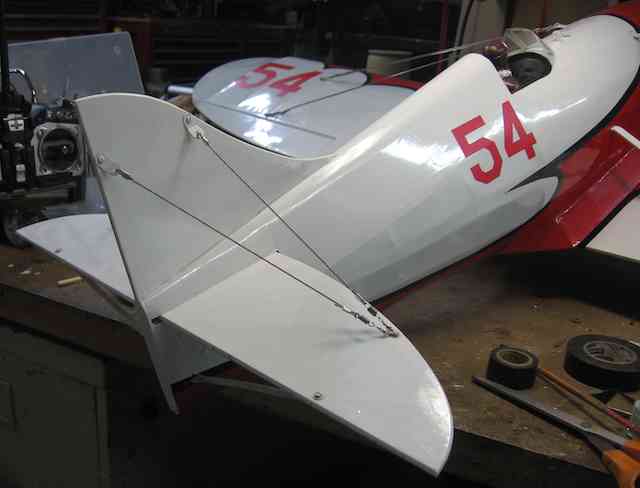 Re: Maxford Gee Bee E/Y: As I assembled the rather complex ARF, it slowly dawned on me that it was not a Gee Bee "E" but a Gee Bee model a"Y". The Y version had a longer fuselage, two cockpits with the front covered over for racing, a three piece windshield and different horizontal and vertical stabilizer bracing/rigging. The model had no provisions for upper wing rigging and tail rigging, which I dutifully added. The black striping on the model is much too wide, but I think I'll leave it that alone. I'll be using the 15x8 APC prop like Greg Gimlick used, a Cobra Scorpion 3525/12 motor and a 60 amp Scorpion speed control, with built-in switch mode BEC, and 4S 4500mAh LiPos. 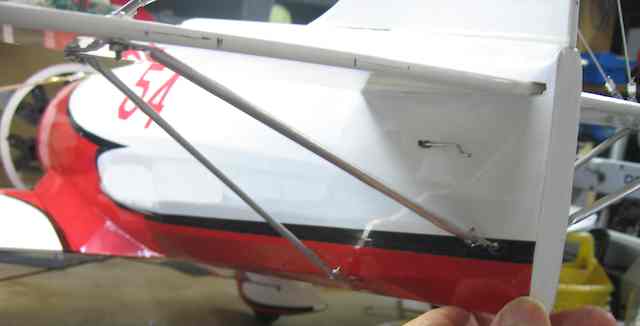
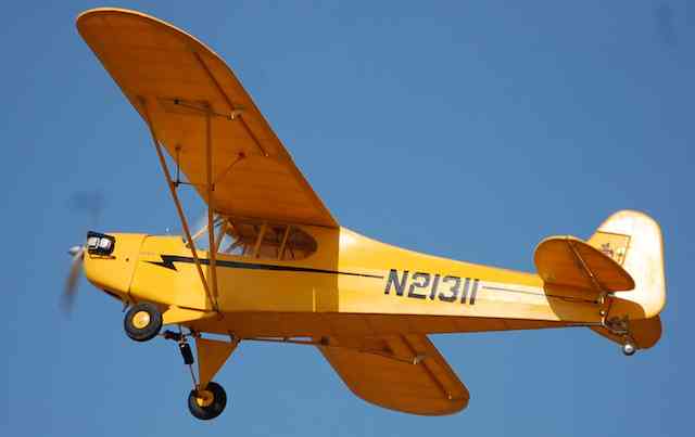
My recently finished Sig 1/6 scale Cub is flying beautifully with the ancient AstroFlight 25 geared brushed motor and "dumb" AF 211 speed control. It is supplemented by a Li-Saver for LVC, and a UBEC for 5 volt servo power. I'm using the Optima receiver's SPC port to separately power the receiver alone as recommended by Hitec. Using the SPC port has the benefit that the motor/receiver battery voltage reads out on my Aurora 9's touch screen. Optima receivers have a tranceiver function when using the SPC port. Optima receivers can operate on up to 35 volts from the motor battery, mine is getting 22+volts from the two 2200 3S LiPos. I'm getting around 9 minutes duration with a couple of loops and mostly scale-like cruising flight. The Zen-like pleasures of flying a nice large Cub model should not be overlooked even though Cubs are so common. 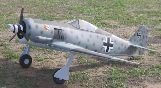 My hero, Bob Goff, maidened his latest Cleveland Plans 1/5 scale conversion model, a FW 190, yesterday at Fairview Park in Costa Mesa. He was doing inverted circles etc. This one only took him six months to build. His Cleveland Plan builds include the Dornier Pfiel Anteater, Douglas A-20, Spitfire, Jungmeister, Amelia's Lockheed Electra, and a few more that I can't remember. He uses the plans mainly for outlines and traces parts on tracing paper, redesigning for geared electric power RC and retracts, etc. as he goes along. Some of his models are featured in great You Tube videos. Bob's a master builder and aerobatic flyer. Keep 'Em Flying Gary Gullikson, Garden Grove, CA Maxford Gee Bee Flying Update
I have been struggling with my ARF Maxford Gee Bee E(Y). It is now flying fairly well, but I am remounting the #$%^ wheel leggings/pants with industrial velcro instead of wood screws. My test pilot, Bob Goff, was fiinally able to get it flying hands off, but it needs further work to become an easier frequent flyer. It is close-coupled and the CG is critical. It flys like my old Peashooter design. It is not for noobs! Read about it here.  Gary Gullikson, E-Challenged
To Reach Ken Myers, you can land mail to the address at the top of the page. My E-mail address is: KMyersEFO@theampeer.org |