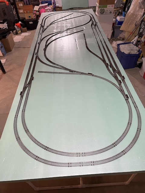
Once ALL of the track was available, it was laid out on the table top. Each time the track was physically laid out on the table top, it still had a problem. It seems that the X-Track CAD track planning program has a problem when using Atlas sectional track on a diagonal. Once the majority of turnouts arrived on November 28, 2022 I put in many, many long days placing track on the table top, finding that it did not work and then working with a new version in X-Trach CAD.
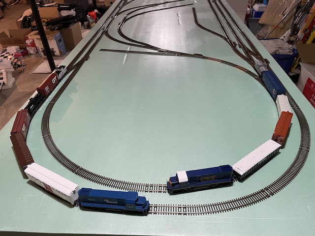
The Galaxy S7 Edge Android phone and 4 LiFe batteries were charged. After carefully checking the trackwork for misaligned rail joiners for the last time, the track was pinned to the foam insulation board using straight pins. The Walthers' CSX GP15-1 led the train, consisting of the gondola battery car, Soo Line 50' Boxcar, Conrail 50' boxcar and CSX caboose. (All of the rolling stock I had at the time.) The train was run for 45 minutes, which was what I believed to be the prototypical run time limit of the 280mAh batteries at that time. Since then, I have discovered that both the 4 LiFePO4 10400 size and 3 Lithium Manganese Oxide 10400 size can safely be used for 55 minutes of prototypical run time. Seven more pieces of rolling stock were ordered from Yankee Dabbler so that two trains could be made up and run at the same time. During the testing, several problematic areas and turnout issues were discovered and corrected. Once the new rolling stock arrived, the testing and "fixing" continued. The details about the problems that arose and their fixes are shared here. The first run with both Dead Rail/Battery on Board trains went very well. The LocoFi™ App and and decoders worked well while controlling both trains at the same time.
With the track plan working well, it was time, December 22, 2022 to procure the Midwest HO Cork Roadbed. While building the original Demo Layout, I had ordered and received 2 boxes of Midwest HO Cork Roadbed with 5 three foot pieces in each box. The cork was never used on the demo layout. I calculated that I needed about 30 three foot sections for this layout. I first went online to see if the local hobby shop, Nankin Hobby in Farmington, MI, had a box of Midwest Cork Roadbed. Nankin Hobby in Farmington, MI, is part of a four store group. Between the four stores, they had one three foot piece of cork roadbed and it wasn't at the Farmington store. I went online to Tower Hobbies, where I'd purchased a lot of RC model plane "stuff" over the years. They also sell model railroad equipment. They had no Midwest roadbed in stock and noted March 2023 as the date they expected it to arrive. I checked Yankee Dabbler and even Amazon, but no Midwest HO Cork Roadbed was available. Finally, on December 23, 2022 I ordered Midwest HO Cork Roadbed from Micro-Mark, where it was also back ordered. At first, Micro-Mark noted an expected delivery date to them of December 2022. By December 28, 2022, Micro-Mark had moved the date to March 2023!
It is very frustrating to not be able to get such simple HO model railroading supplies as track and roadbed. The Woodland Scenics HO Track-Bed™, a different type of roadbed, did seem to be available. On December 28, 2022, I found that TrainWorld noted that they had Midwest HO Cork Roadbed in stock, although it was $10 more than Micro-Mark's price, I decided to order from them, as I did not want to wait until March 2023!!! An order was placed with TRAINWORLD at 7:40 a.m. on December 28, 2022. It arrived on Friday, December 30, 2022 at about 2 p.m. The Micro-Mark order was cancelled. After a lot of prototypical running, over many, many days, I decided to make a HUGE change to the original track plan. Originally, a "mountain" was planned for one end of the layout. 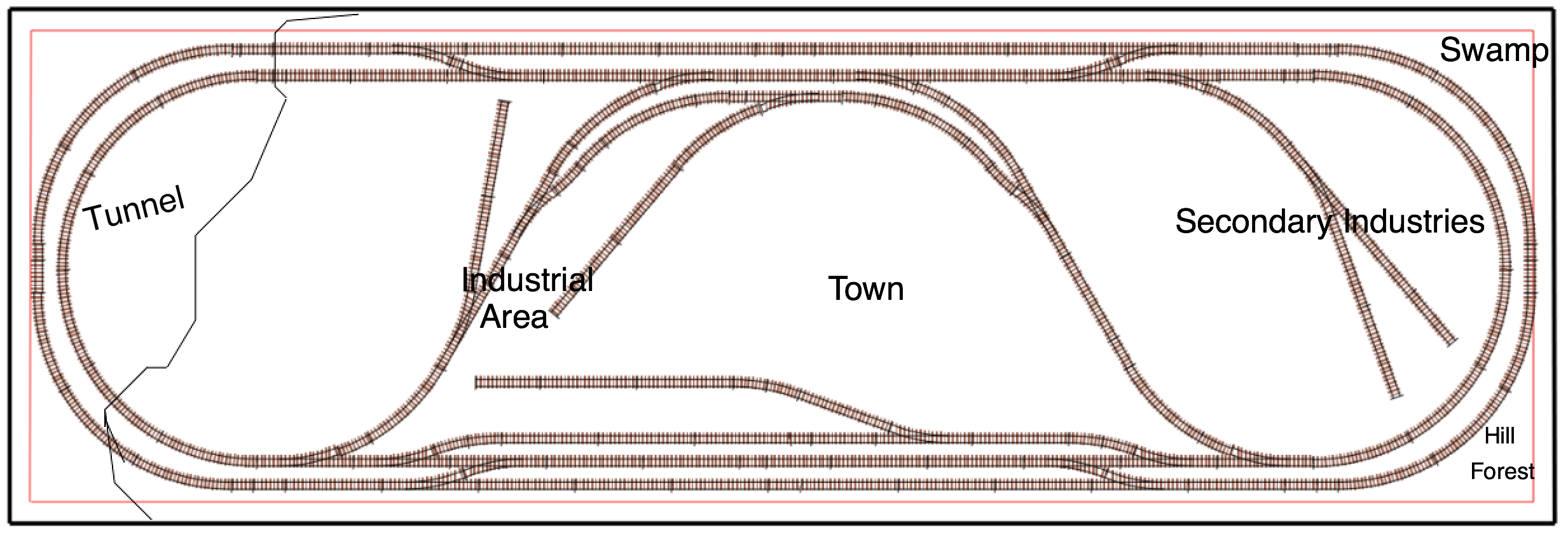 Through continually doing prototypical operations, including a lot of shunting of rolling stock, over a long period of time, it was discovered that operations were, indeed, really more important than some outstanding scenery. 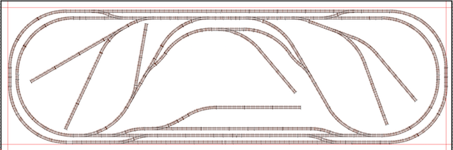
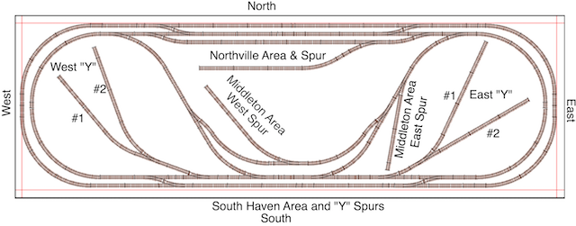
Track Plan Revision 15 The "idea" of a mountain was set aside so that two more sidings could be added to the track plan to add more operational possibilities. 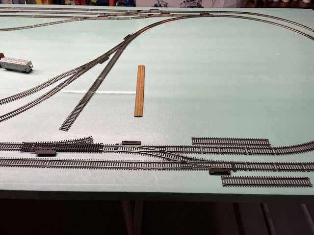 The defective right turnout was flipped over to help plan the new area for the sidings. 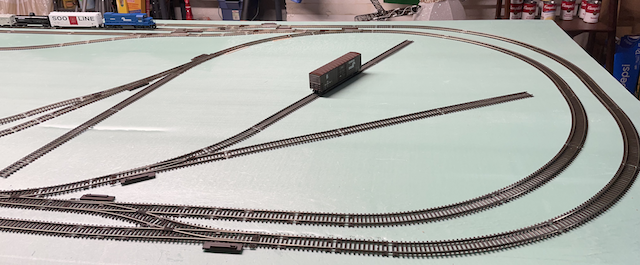 Two Atlas Code 83 18" Left Manual Turnouts were purchased at Nankin Hobby in Farmington, MI. They were installed, along with some extra Code 83 track that I already had on hand. Everything worked well and the prototypical running and testing of the track work continued. With 23 turnouts in the track plan, some problems with a few individual turnouts were inevitable. Unfortunately, over an extended period of time, the problems escalated. More and more issues were discovered through more prototypical running. The problems, issues and fixes are shared here. After getting the track laid and the layout up and running, laying the Midwest Cork Roadbed was a long, tedious and involved process with many steps and sidesteps. While preparing to lay the cork roadbed, I still struggled with the poor quality of the Atlas Code 83 18" Radius Snap Switches. I practiced bending the switches to lay flat on the kitchen counter using the two totally destroyed right snap switches. I was able to bend them into shape, with my hands, using quite a bit of pressure and twisting. 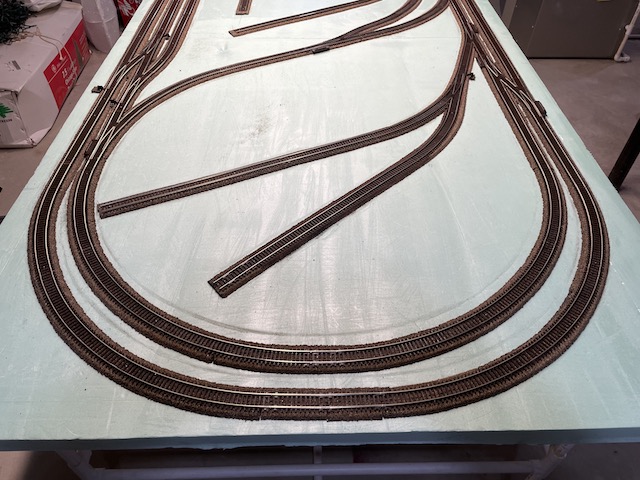 The process started on January 30, 2023 and it was considered completed, and acceptable, on February 9, 2023. The days were long and filled with a lot of problem solving. The details of the process and problems experienced in laying the cork roadbed and the discovery of a broken Walthers' GP15-1 Conrail are shared here.
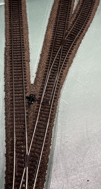
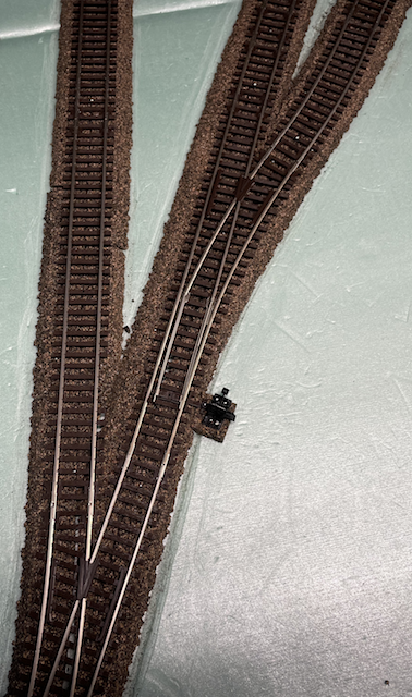
During the installation of the Caboose Industries Ground Throws, which replaced the Atlas stock manual throws, a problem arose.
The photo on the left shows my first attempt at mounting a ground throw in a particular location. the east end of the dogbone. It did not work! The arm of the ground throw was too difficult to throw. Locomotives entering the short east spur hit the ground throw. I had recently watched a YouTube video "Modifying Atlas snap switches". The stock manual throw, on Atlas Snap Switches, is located on the side opposite the diverging route. The video demonstrated how to switch the throw side to the diverging route side of the Snap Switch. I was hesitant to try it. Removing a switch is always a lot of work and requires removal of other sections of track that are working well. Many YouTube videos contain incorrect or only partially correct information. With a lot of trepidation, I did remove the switch going into the east side of the dogbone route and performed the modification. After removing several sections of track, the Snap Switch was removed. The modification, demonstrated in the video, went quite easily, and worked well. The photo on the right shows the new location of the ground throw on the opposite side. The turnout and track sections were reinstalled, as well as the ground throw being repositioned to the divergent side. The Conrail was used to fully test the reworked area of track and no problems were found. The same process was used to modify the throw side of both inner loop inside crossover Snap Switches to keep the ground throws from possibly fouling the throat of the spurs and to make them easier to throw. The change over from the stock Atlas manual throws to Caboose Industries ground throws was completed on February 15, 2023, after about a week's work, while also doing prototypical runs to continue to detect problematic areas of the track-work.
Prototypical operations were run over several days to continue testing for troublesome spots and places where the track still needed more leveling. The switch between the most inner north side parallel track and the north spur required more work in the Snap Switch area to keep the train from derailing while pushing cars onto that spur. A dip in the north side's most outer parallel track was discovered and leveled. During the prototypical running, with shunting, picks of various types were used for uncoupling. They included a meat skewer, toothpick and previously purchased Kadee uncoupling tool. I found none of them yielded satisfactory and consistant results. I watched a YouTube video that showed a homemade version of the Rix Sticker -- Magnetic Uncoupling Tool portable, manual magnetic uncoupler. I made and tried various design versions of that tool using the magnets that I had on hand. They all failed because the magnets on the tool would grab the Kadee coupler and pull the car, or cars off of the track. Conclusion, Kadee track magnets will be used. While doing a prototypical shunting run, to discover where the magnets needed to be placed, three problems were discovered.
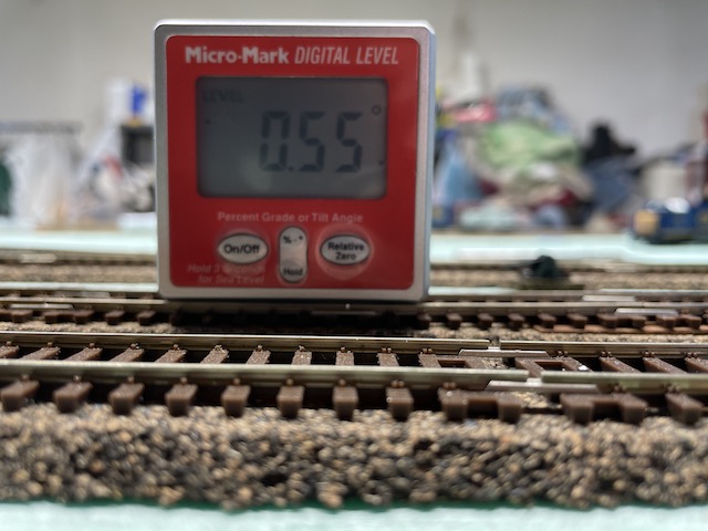
Layout Revision 15's south side inner and outer loop crossovers of the track layout were switched around so that the operations of two trains, doing prototypical shunting runs at the same time, one shunting cars on the north side spurs and the other the south side spurs, should not interfere with each other as much.  By reversing the crossover directions, Layout Revision 16 allows trains entering the area of the south side to bypass most of the area where the south side shunting is taking place by moving to the outer loop through that area. The crossover Snap Switches were physically exchanged with some modification to the track-work as well. While the previous statement appears simple enough, the pinned ground throws had to be removed, as well as some pinned down track sections removed and rearranged and then everything had to be put back in its new positions and pinned down again. It was a really long process, about 3 hours, but thank goodness nothing was glued down! Only one of the left crossover switches had to be converted back to having the slide throw on the non-divergent side. The other was used to fix the problem with the locomotive hitting the ground throw at the entrance of the short east spur. Once the new track pattern was laid, it was tested using some prototypical shunting to find any new problem areas. When the turnout at the throat of the short east spur was installed, a track connector was not installed correctly. That caused a bump in the rails. The connector was reinstalled, but that changed the throw on the ground throw. The ground throw was removed, and then replaced with the ground throw adjusted correctly to provide the proper throw. Prototypical shunting continued to determine magnet placement for the Kadee uncoupling. The whole process, with photos, is shared here. At the end of February, 2023 4 packages of Kadee #322 HO Scale Between-the-Rails Code 83 Delayed-Action Magnetic Uncouplers were purchased at Nankin Hobby in Farmington, MI along with a package of Kadee #141 long underset shank couplers, to possibly fix the locomotive pushing problem with the train set caboose. 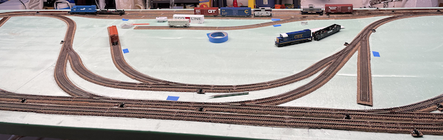 Two inch pieces of blue painter's masking tape were used to mark where the magnets were to be originally placed. 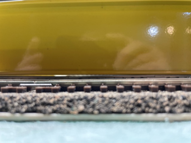 A 4', yellow, metal level was used to check to see if the magnet placement would be level. It needs to be. The photo shows the gap under the level, which indicated that that position needed to be leveled.
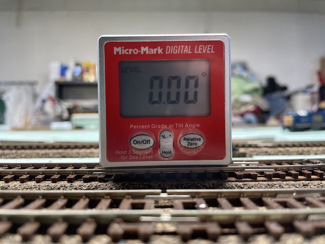
A Micro-Mark Digital Level was used to adjust that track location to level. 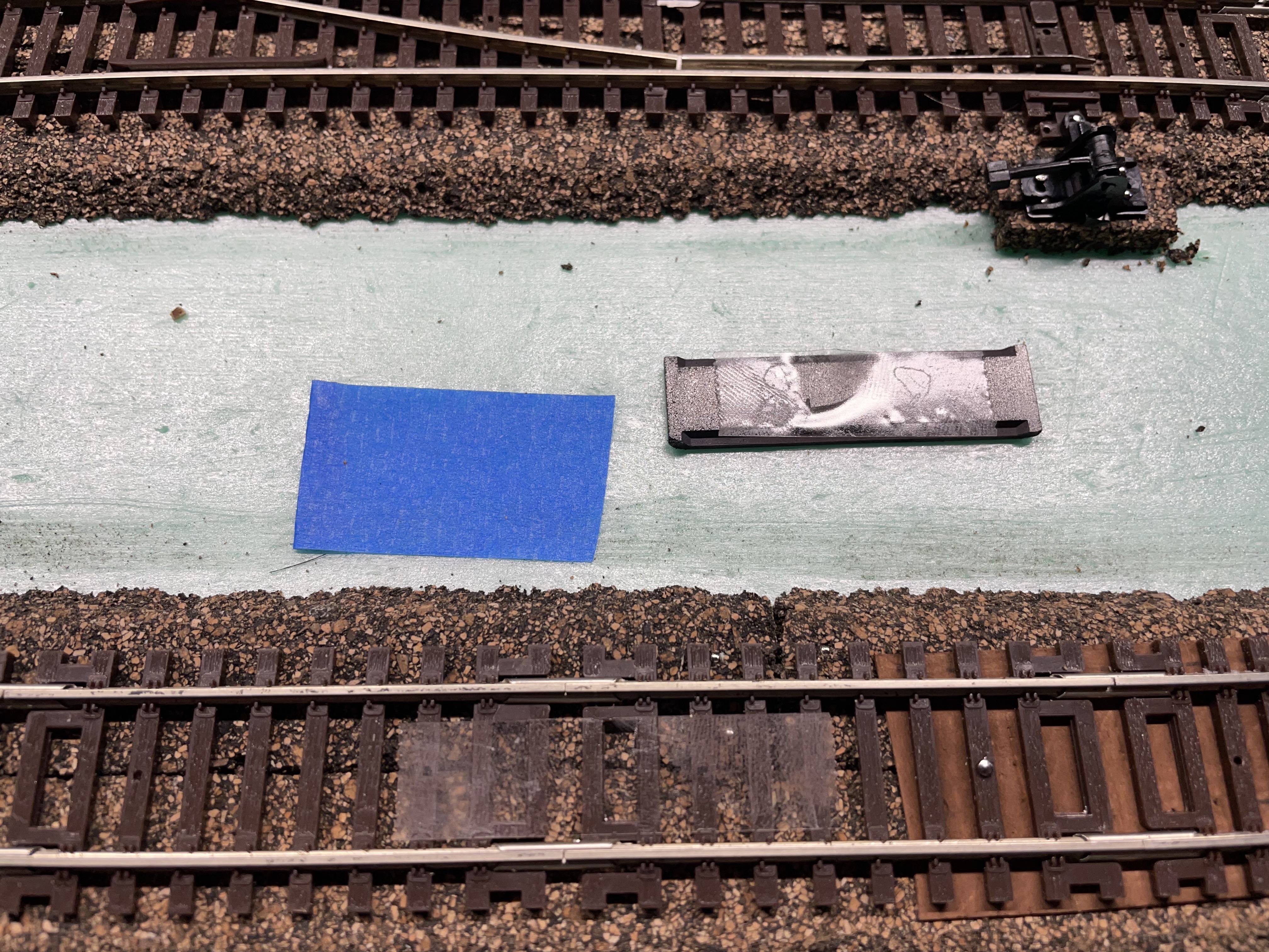 After all of the proposed magnet sites were leveled, the magnets were secured in place with double-sided Scotch tape in case they needed to be repositioned, and some of them did! One piece of tape was placed between the rails and another on the down, or backside, of the magnet. 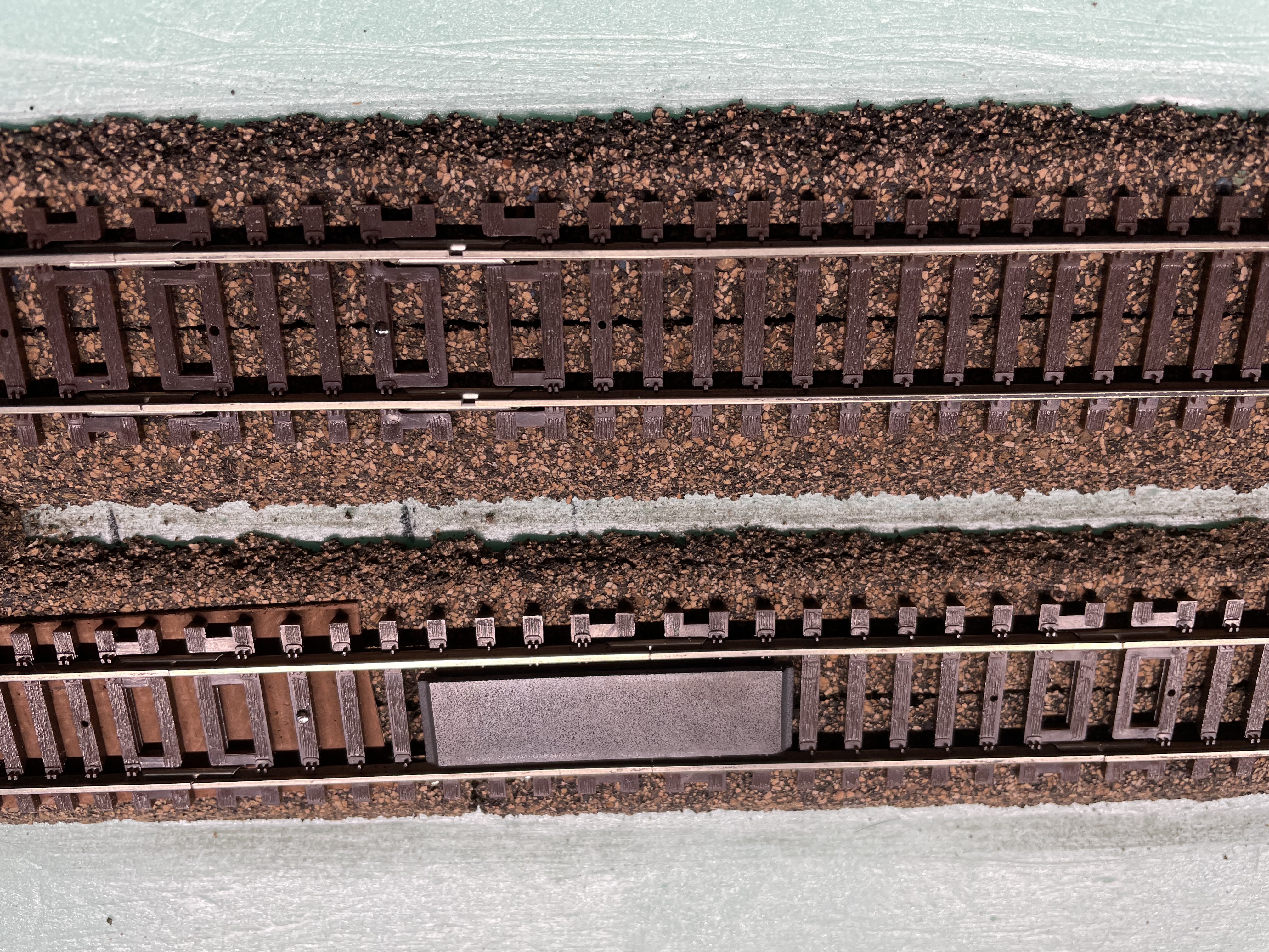 The magnet was taped into position. The Kadee #205 Multi-purpose Height Gauge was used to align and check the height of the magnet. To verify the correct trip pin height, each individual car was tested manually through the magnet area and the locomotives were run at their lowest speed through the magnet areas. Even though the Kadee height gauge was used when installing Kadee couplers to the locomotives and rolling stock, each car and the locomotives with their attached battery cars were checked individually. Some of the cars and both locomotives needed their trip pins adjusted with the Kadee #237 Coupler Trip Pin Pliers. The first hour of testing and practicing using the uncoupler magnets proved to be quite frustrating. Several problems occurred.
The YouTube video titled, "Couplers - 7 Secrets to RELIABLE Kadee Remote Magnetic Uncoupling on your HO Scale Model Railroad!", was watched again. The Kadee height gauge was used, once again, to check the coupler height of each piece of rolling stock and to also check for any coupler "droop". A train, consisting of the locomotive, with its battery car, and all nine pieces of the current rolling stock, was used. (This whole procedure was "WRONG"! See the archived new procedure.) After the modifications to the magnet placement, coupler adjustments and several hours of prototypical shunting, the coupling and uncoupling worked as expected. Update: 02/06/24 For over a year of running both of the diesels, with various rolling stock combinations, for many hours on the layout, there were no problems with unwanted uncouplings of rolling stock when passing over the magnets on the inner loop. The IHC 2-8-0 Consolidation was added to the locomotive roster on December 28, 2023. All of a sudden, when the IHC 2-8-0 was pulling a train at 35 mph, there were unwanted uncouplings of cars over the South Haven magnet and east and west end magnets of the inner loop through Northville. Both diesels were tried at the same speed as the 2-8-0, using the same rolling stock, and the unwanted uncouplings didn't occur. Several methods were used to attempt to isolate and identify what was causing the problem. The small Micro-Mark 2-In-1 High-Precision Miniature Digital Level and shims were used to try and get the problem magnet areas very close to level. That did not help. Several days were spent trying to assess and correct the problem with no success. Six different pieces of rolling stock, in six different positions in the train, had unwanted uncoupling problems during a "test" run using the 2-8-0. Reversing the cars ends and repositioning their placement in the train made no difference. They still had unwanted uncouplings! I had previously viewed a YouTube video titled, "Couplers - 7 Secrets to RELIABLE Kadee Remote Magnetic Uncoupling on your HO Scale Model Railroad!". I tried a version of the video's tip #5, adding a "drag wire" on the axles. I tried the demonstrated method using the smallest diameter piano wire that I had on hand, 0.019". After placing the demonstrated "drag wire" on all of the cars, the problem cars were made into a train and pulled behind the 2-8-0. Success, but... When all 10 pieces of rolling stock were placed behind the 2-8-0, on my flat layout, the train wouldn't budge! Too much drag! I redid all of the "drag wires" using 26 gauge beading wire which is 0.0159" in diameter. I did not make the hooks as shown in the video. I wrapped one end around the truck's bolster and the other around one axle. This method worked and, most importantly, had almost no affect on battery run time. On February 8, 2023, I ordered 3 sets of Tichy Train Group Track Stop #8165 ($7.95 Pkg. 2 each) and 4 packages of Caboose Industries 5202S HO Scale Sprung Ground Throws ($16.95 Pkg. 5 each) and shipping for all 7 items was $13.95. 23 ground throws were required, but a 5 pack had been previously purchased. The ground throws worked really well, and all 23 of the problematic Atlas Code 83 manual switch machines were replaced. In the middle of March, 2023, an attempt was made to assemble the Track Stops that looked so good on the Micro-Mark Webpage. As a lifelong "modeler", with well over 65 years of experience in many types of modeling, I did not anticipate any problems when assembling these simple Track Stops. I WAS WRONG! I have suffered through all kinds of poor assembly instructions and directions for all types of models, and other items as well. Once a lot of modeling supplies started arriving from China, Chinglish instructions became a thing to suffer through as well. 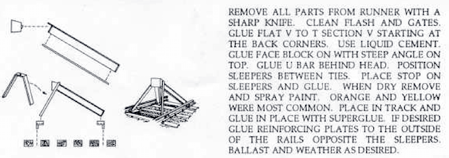 The Tichy instructions rank right up there with the worst that I've ever seen. Using the parts diagram as reference, the actual parts on the sprue tree and their written instructions, I wrote a "translation" of their instructions for my own benefit, and to share here. Once the assembly procedure was figured out, and it took a long time, the assembly was started on the first Track Stop. Assembling the I-beams, the first step, went well. Adding the tiny, tiny, tiny face block was a nightmare. Many, many methods were tried until one was hit upon that actually sort of worked. What they call a U BAR was next. It is not really a U-shape. It is a V-shape with a flat bottom and diagonal legs. That part is very, very, very thin. While removing it from the sprue, both of the diagonals were broken. Rats! Several attempts were made to glue the broken legs back together. They all failed. A piece of small diameter wire was bent to the correct shape to replace their U BAR. That worked, sort of. The assembly was completed with continuing frustration. An attempt was made to assemble the second one in the package and it was equally frustrating. Gluing the face block to the completed I-beam was still a challenge. With extremely great care, the U BAR was successfully removed from the sprue with no breakage. The U Bar was taped in place, to be glued later. That's how the wire was done in the first attempt. While moving the assembled track stop around, for gluing that assembly to the sleepers, one of the diagonals broke in two. Total frustration! Over six and one half hours was spent to assemble two unacceptable track stops! I could have modeled the track stops out of wood, but opted to order 4 packages of Peco North American-Style Code 83 Hayes Bumper - Kit pkg(2) from Walthers. They looked easier to assemble, especially since the face plate appeared to be part of the I-beam molding and the U BAR, at the front, appeared to be made of more substancial material. In the photo on Walthers' Web page, it appears to have only two parts. The price for these Peco brand Hayes Bumpers appeared to be fair enough, but the shipping for these 4 small, lightweight packages was outrageous at $12.95!!! Really, I mean really, $12.95! They arrived in the USPS mail on Monday, March 20, 2023. My rewrite of the directions was deleted, since I cannot recommend them to anyone. I wrote a review of these Tichy track stops for the Micro-Mark Web page. I described my modeling experience and noted the problems that I had. I gave the product a one star rating. They never posted my review. Their Webpage for this product still notes, "No reviews available". I did find a review on ebay. That page may be gone now, as they noted, "Last one!". The review said, "Lousy - Poor instruction too fragile to assemble". Update: July 27, 2023 7 of the Peco brand Hayes Bumpers were assembled. They were super easy to assemble and look good. They still need to be painted and weathered. I highly recommend them. Update: November 9, 2023 I received an email from Micro-Mark this morning. It noted "Hidden treasures await in our CLOSEOUTS department!" I bet you can guess what was being closed out!!! Yep, Tichy Hayes-Built Bumper Stops (Set of 2) HO Scale. |