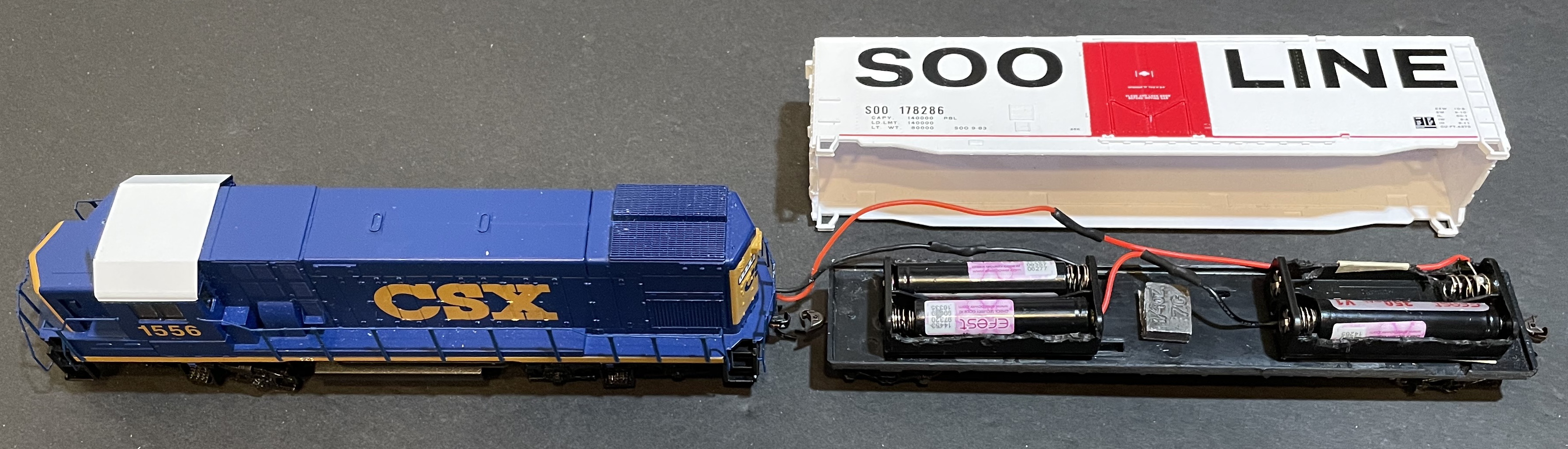
December 2023 The Products I Am Currently Using for Dead Rail/Battery on Board Locomotives The Locomotives: Walthers' EMD GP15-1 - Standard DC - CSX from a Walthers' Flyer Express Fast-Freight Train Set and a Walthers' EMD GP15-1 - Standard DC -- Conrail. DULLHB - LocoFi™ 3 WiFi Sound Decoder for HO Locomotives: one installed in each locomotive. Rolling Stock for Battery Cars: A Walthers' Trainline 53' Smooth-side gondola, Norfolk Southern with a DIY cover & Trainline 50' Plug-Door Boxcar Soo Line Boxcar. Battery Boxes: 2 each wired in series.
The AAA battery boxes are used with Lithium-ion 10440 size cylindrical batteries. The AA 3 in-line battery box is used with 14500 size cylindrical batteries. The boxes have their wings, that wrap around the tops of the batteries, removed to make inserting and removing the batteries easier. Connectors: 32-pin Micro Connector Set from Micro-Mark
Batteries
4 each Lithium Iron Phosphate, LiFePO4 (LiFe, IFR) Soshine 10440 LiFePO4 Rechargeable Batteries, which are no longer available from Amazon. Please see my note on "Battery Availability". 3 each Lithium Manganese Oxide, LiMn2O4 (LMO, IMR) 14500 Efest IMR14500 V2 650mAh High Discharge Button Top batteries. Because of the battery box used, flat top batteries would have been a better fit. SkyRC MC3000 Multi-Chemistry Charger The following installs demonstrate how LocoFi™ was installed for Dead Rail, battery power, in my Walthers' Trainline GP15-1s. There is also information on how the trailing battery cars were created. If the LocoFi™ module has not been ordered yet, now would be a good time to do it. Using a Li-Po battery is NOT recommended and only mentioned here for archival purposes. Important information regarding the use of Lithium Polymer (Li-Po) batteries is found here.
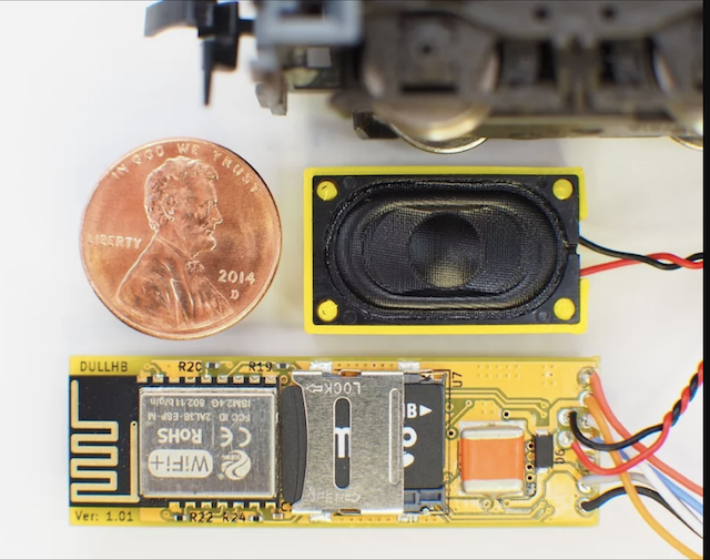
Seven wires extend from the module and may seem confusing or that the hook-up task is formidable, but it is really simple. The white wire goes to the front LED positive, the yellow to the rear LED positive and the blue wire is the common negative wire for both LEDs. The red and black wires go to the "pure" DC power source, the battery in this case, and the orange and gray go to the motor.
Animated GIF From the LocoFi™ Website These are now my preferred connectors, as I had tried a lot of other connectors and these worked out the best for me. This link opens a new tab where I share my information and use of these battery connectors that are used between the LocoFi™ module in the locomotive and the battery pack in the trailing battery car. There is also some informaation on the linked page about the creation of the trailing battery cars. I made a lot of mistakes that cost me time, aggravation, frustration, and money. Railroad Modelling requires patients, knowledge, modeling skills and the correct tools for the job. My patients was a bit too short at times and I lacked some of the knowledge required for the Dead Rail conversion to be done correctly the first time. I made so many mistakes that a second Walthers EMD GP15-1 was ordered from Amazon on March 17, 2022. I accidentally popped out the rear drive shaft between the flywheel on the motor and the gear housing on the rear truck of the CSX locomotive. After spending most of the day, off and on, trying to reinsert the drive shaft, I was able to do it successfully, but I'd already ordered the new locomotive. I found that Amazon does not price the same locomotives, but with different road names, at the same price. On that day, the locomotive with the CSX markings was priced at $89.98 and the one with the Conrail markings was only $67.95.
Since only the chassis was important, the Conrail version was ordered and arrived that evening in no shipping box. It was only in the manufacturer's box. The shipping label had been applied directly to the manufacturer's box. The locomotive package contained the basic locomotive with the horn piece and the snowplow "blades" packed separately. It also contained the same maintenance and coupler assembly instructions as the train set. Using the transformer that came with the train set, the new locomotive was tested on the oval of track that came with the train set. This unit also ran very smoothly at low speed.
Several problems were encountered while getting my Dead Rail trains up and running. They included;
Details about the problems, and the way that I fixed those problems, is archived here.
For now, it is not important to select an appropriate style and size of rolling stock to be used for the trailing battery car. That selection can be done once the physical battery pack has been assembled. Before continuing, the type and capacity of Lithium-ion batteries must be selected and ordered, as well as the number of, and style of battery boxes. The Micro-Mark connectors should be ordered. An appropriate Battery Charger should be ordered. Battery and Charger Selection Information is found here, The batteries that I use, as well as the battery boxes, are noted at the top of this page. AAA 1.5V "dry cell" batteries have approximately the same physical size as 10440 Lithium-ion cylindrical batteries, 10mm in diameter by 44 millimeters long. Based on the width and length of some typical HO rolling stock, AAA battery boxes were selected to hold the individual cylindrical batteries for this conversion. The battery boxes fit inside several choices of rolling stock. Two AAA side-by-side battery boxes, connected in series, were used to create the resultant battery pack. A connector, sized as a AAA battery, is used to fill and connect one slot, when three IMR or INR 10440 size cylindrical batteries are used. That connector battery is not used when 4 10440 size (AAA) size LiFe batteries are used. The two AAA battery boxes were modified to make the insertion and removal of the chosen Lithium-Ion batteries easier. The physical conversion of the battery car is archived here. WARNING! ABSOLUTELY AVOID TOUCHING THE SPEAKER DIAPHRAGM DURING THE HANDLING, FITMENT AND INSTALLATION PROCESS. 1. The LocoFi™ module
A soldering iron and solder are not needed during the preparation to install. Steam sounds are now available using the FREE 2.38 version of the LocoFi™ App. It should be noted that the App is available for Android and Amazon Fire devices in November of 2023. An iOS App is said to be coming. Watch the "LocoFi™ App - Installation" video, to the control device, is demonstrated in this short video. This video was posted 5 years ago, but is short and still demonstrates the method. Watch the first part of the DO THIS FIRST!!! video to the 3 minute 52 second mark. The video demonstrates how to get the loco running using the chosen control device and the Wi-Fi in the module. This video was posted 3 years ago, but the method is still valid, although the App's interface and functions have been updated several times.
The LocoFi™ team triple checks the module and speaker before sending it out. Both to satisfy myself that the module and speaker were okay and to select the desired sounds, before soldering all the wires together for installation in the locomotive, I hooked up just the battery pack to the LocoFi™ module, being absolutely certain that none of the other wires could make contact with each other. 1. The ends of the red and black leads on the LocoFi™ module and the red and black leads on two AAA side-by-side battery boxes were bared about 1/4". No other leads were bared at this time. No leads were cut. That is for later.
I started the previously downloaded LocoFi™ App on an old Galaxy S7 Edge, my control device, that was just lying around the house. The phone App and the LocoFi™ module were connected via the onboard Wi-Fi in the LocoFi™ module as shown in the first part of the video DO THIS FIRST!!!. 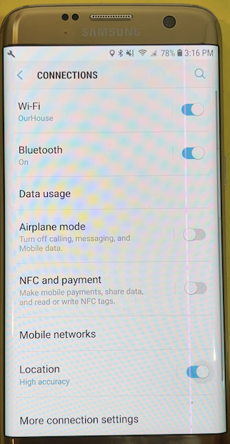 One thing that was not shown in the video was that Location should be set to High Accuracy, which is on the Connections screen of the device. To navigate there Settings>Connections and check to see that High Accuracy is turned on. Then go to Wi-Fi to select LOCO-xxxxxx, the alphanumeric characters, and set that Wi-Fi network as the Current Network. The App opens to the Splash screen. You can change the engineer's name when it opens the first time, or do it later. Tap OK to go to the Main screen. Tap Manage and then Tap the name of the locomotive, which are the alphanumeric characters. This brings up the Dashboard screen. Upon moving from the Main screen to the Dashboard, a firmware update to the module was required before the test could be conducted. The process went easily and well. When the Start Button, on the bottom center of the Dashboard screen, was pushed, the locomotive's start up sound was activated, and when the bell and the horn buttons were pushed, their sounds were activated as well. All of the sounds sounded great, but the question arose, are the sounds correct for this locomotive? I first shut down the module and phone. The arrow at the top, left of the Dashboard screen was tapped to return the main screen. The three vertical dot menu at the top, right of the Main screen was tapped and Exit was chosen. The module was shut down by removing the batteries. The control device, in this case the phone, was turned off. The sound files, in the form of wave files (.wav) and their associated text files (.txt) are located on a Micro-SD card on the module. View Replacing microSD card to change the sound and text files. LocoFi™ supplies an adapter for the Micro-SD card so that it will fit in a standard SD card device. The Resources page on the LocoFi™ Website has a section on Sounds. The information in the Sounds section notes where to download the sounds and associated text files from. There is also a Quick Sound Editing Guide link that demonstrates how to modify preexisting sounds or create your own sounds. For my EMD GP15-1s, I downloaded the files from the Sound section of the Forum on the LocoFi™ Website; EMD 567 Sounds, a post by user dmahan. The files were copied to the Micro-SD card to replace the existing files and the Micro-SD card was returned to its place on the module. The new sounds were tried and found to be to my liking. The engine sound was shut down by pressing the start/stop button again. The arrow at the top, left of the Dashboard screen was tapped to return the main screen. The three vertical dot menu at the top, right of the Main screen was tapped and Exit was chosen. The module was shut down by removing the batteries. The control device, in this case the phone, was turned off. At this point, the LocoFi™ module was ready to be installed. The measuring, cutting and soldering of the wires completed the installation. It was also necessary to fit, solder, fit and try until all of the components were hooked up and fitting in the locomotive body shell correctly.
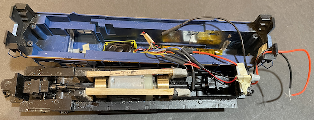
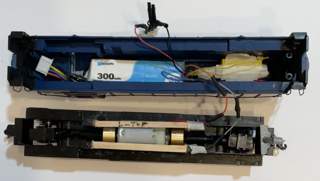
The components are installed. The wood frame, over the motor, was there to hold up the Li-Po battery. The LocoFi™ module and speaker are shown installed in the locomotive. Li-Po batteries should not be used in Dead Rail conversions. Installing the LocoFi™ decoder with its attached speaker is very easy. The red and black wires, without their Micro-Mark connectors soldered on yet, can be seen being routed out of the rear of the locomotive. The following sections cover the physical installations of the LocoFi™ module into the Walthers' GP15-1s. They are listed in order from the most relevant and useful to the least. The photos in all sections should be useful for ideas on how things were actually done. On day 11 of the roadbed installation, the original Conrail Walthers GP15-1, was taken apart, examined and there was no way found to "fix" a rear truck problem. It would not swing freely side-to-side and would derail through some switches. A new Conrail Walthers Trainline GP15-1 was ordered from Amazon before 6 a.m. on Thursday, February 9, 2023. It was on sale and priced at $78.98. That was $9 more than the first Conrail. It arrived at 7:30 p.m. that same day. 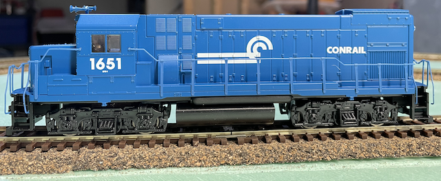
Note the rear, left handrail is loose because it was broken off. Upon arrival and first inspection, it was noted that this iteration came with the horns attached and that the front and rear trucks moved freely. The process required to convert this locomotive to Dead Rail is archived here.
Even though the Walthers EMD GP15-1 CSX, powered by a small, 3S 11.1V 300mAh Li-Po, proved to be a technical success, I was not satisfied with that conversion. It was not an easy conversion to do. It required a lot of modeling skills and tools. The Li-Po battery required a Li-Po charger and the knowledge of safe Li-Po charging practices, as well as the safe storage of Li-Po batteries. Li-Po batteries really should not be used for Dead Rail/Battery on Board power. The modifications, for using a Li-Po battery in the locomotive, are archived latter. THE ARCHIVE IS FOR INFORMATIONAL PURPOSES ONLY. NEVER USE A Li-Po IN A LOCOMOTIVE OR BATTERY CAR FOR A DEAD RAIL CONVERSION! The details on converting the CSX GP15-1 to use a battery car are found here. These details are probably the most useful. The information about using three Lithium Manganese Oxide (LMO, IMR) was moved to here. The locomotive had its shell removed and the shell modified to use a trailing battery car, and had the LocoFi™ module and speaker installed into the shell. After the locomotive was "buttoned up", the locomotive and its attached battery car were tested on the demo layout. After passing the running test on the demo layout, it was time to set up and configure the locomotive following the directions in the two LocoFi™ videos found on the LocoFi™ videos page. The actual install details of the modifications and install are found here. Update: May 13, 2022 I ABSOLUTELY RECOMMEND THAT NO ONE DO THIS CONVERSION USING A Li-Po in the body shell. A better and safer conversion is demonstrated later in this article! This Li-Po conversion was changed to use a trailing battery car. Three cylindrical IMR 10440 size batteries were connected in series (S) to create a 3S IMR 350mAh Lithium-ion resultant battery pack. This conversion with the 3S Li-Po was a feasibility study. While it worked, and worked well, it is NOT something that most people have the ability to do and use safely. AGAIN, I ABSOLUTELY RECOMMEND THAT NO ONE USE THE FOLLOWING INFORMATION AS A HOW-TO. The information is presented only for informational purposes and to increase the reader's knowledge base. The couplers and the four screws, that hold the body shell to the chassis, were removed to lift the body shell off the chassis so that some body shell interior physical measurements could be made for the fitment of the LocoFi™ module, with its attached speaker, The Walthers GP15-1 has a printed circuit board (PCB) in it that controls whether the front or back light is on, depending on the direction that the locomotive is running. Both of the LED lights easily pulled/came right out of their holders even though the supplied instructions noted that they were glued in. Because a form of Dead Rail (battery power) was going to be used, several locomotive exterior and interior dimensions were measured and noted on a simple CAD drawing to aid in the fitment of the LocoFi™ decoder, speaker and battery.
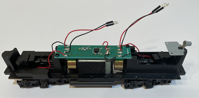
Chassis as delivered Once the CAD drawings indicated that all of the components could possibly fit in the locomotive, the track pick-up power wires, motor connections and LEDs were unsoldered from the PCB and the PCB was removed by unscrewing it from the chassis.
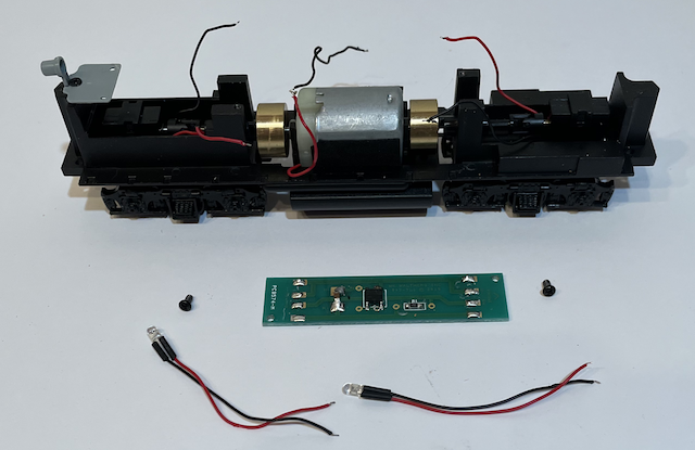
The PCB removed For this unacceptable conversion, the battery was placed into the position it was to occupy in the locomotive and the shell and chassis were joined. After some modifications to the inside, top of the body shell, it fit! A second Walthers' GP15-1, with Conrail markings, was purchased and the body shell was very different. The second body shell was made up of different molded parts from the first and no modification was needed to fit the battery. The leads from the front and rear trucks had their bared wires snipped. The leads were doubled over themselves and heat shrink applied over all four doubled over leads. Later the power wipers, used to pick up power from the track by wiping on the metal wheels, and the wire pieces, were removed.
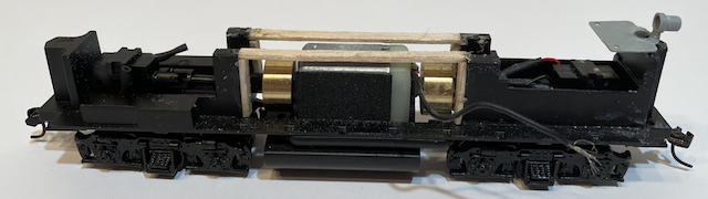
Battery Platform Over Motor The space assigned to the battery pack was mostly over the motor. A 1/16" x 1/8" balsa wood frame was constructed and glued into place to help support the battery and keep it away from the motor. This modification is no longer necessary as the battery is in a trailing car, not in the locomotive. The snowplow parts, for the Walther's EMD GP15-1, were not provided in the train set. Because of the way that the battery pack was originally fitted required that the body shell be removed to install the battery and remove it, which is not really handy! The plastic part, that the plow attaches to, was easily pulled from the main body shell. The slot, where the coupler extends through the shell, was widened a bit to allow the coupler body to slide into the widened slot of the body shell. Again, this modification is no longer necessary as the resultant battery pack is in a trailing car, not in the locomotive. While reassembling and attaching the couplers, the rear light bracket holder was accidentally broken off the chassis and the negative motor lead "disappeared". A new negative motor lead was soldered to the motor and the rear light bracket glued back on.
|